
BG-FS8260 - Adapter BZBGear - Free user manual and instructions
Find the device manual for free BG-FS8260 BZBGear in PDF.


| Product Type | AC/DC Power Adapter |
| Model | BG-FS8260 |
| Brand | BZBGear |
| Input Voltage | 100–240 V AC, 50/60 Hz |
| Output Voltage | 12 V DC |
| Output Current | 2 A |
| Power Rating | 24 W |
| Connector Type | DC barrel jack (5.5 mm x 2.5 mm) |
| Plug Type | US standard (Type A) |
| Dimensions (L x W x H) | 90 mm x 45 mm x 30 mm |
| Weight | 150 g |
| Cable Length | 1.5 m |
| Protection Features | Overcurrent, short circuit, overvoltage |
| LED Indicator | Yes (power on) |
| Operating Temperature | 0°C to 40°C |
| Safety Certifications | CE, FCC, RoHS |
| Compatible Devices | Laptops, monitors, routers, LED strips (12 V) |
| Power Cord Included | Yes (detachable) |
| Warranty | 1 year |
| Cleaning Instructions | Wipe with dry cloth; do not use liquids |
Frequently Asked Questions - BG-FS8260 BZBGear
User questions about BG-FS8260 BZBGear
0 question about this device. Answer the ones you know or ask your own.
Ask a new question about this device
Download the instructions for your Adapter in PDF format for free! Find your manual BG-FS8260 - BZBGear and take your electronic device back in hand. On this page are published all the documents necessary for the use of your device. BG-FS8260 by BZBGear.
USER MANUAL BG-FS8260 BZBGear
natural_image
Illustration of a multi-tiered network switch unit with multiple ports and connectors (no text or labels visible)PoE+ Series Switches
8/16/24/48-PORT GIGABIT L2+ POE+ MANAGED SWITCH
Quick Start Guide
Introduction
Thank you for choosing PoE+ Series Switches. This guide is designed to familiarize you with the layout of the switches and describes how to deploy the switches in your network.

Accessories

natural_image
Line drawing of a coiled electrical plug with two terminal connectors (no text or symbols)Power Cable x1

natural_image
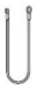
Coiled electrical cable with two connectors (no text or symbols visible)Console Cable x1 Grounding Cable x1


Hardware Overview
Front Panel Ports
S3150-8T2FP/S3260-8T2FP

S3260-16T4FP

S3400-24T4FP

S3400-48T4SP

| Ports | Description |
| RJ45 | 10/100/1000BASE-T ports for Ethernet connection |
| RJ45/SFP Combo | One RJ45 port and one SFP slot, with one port active at a time |
| SFP | SFP ports for 1G transceivers |
| SFP+ | SFP+ ports for 10G transceivers |
| Console | An RJ45 console port for serial management |
Front Panel Button
S3150-8T2FP/S3260-8T2FP

S3260-16T4FP

S3400-24T4FP

Button Description
Reset Restart and restore factory default settings.
S3400-48T8SP

Button Description
SWAP
Press the button and the indicator is on, and the indicator will automatically turn off after a while. If the indicator is on, the Ethernet port indicator indicates PoE power supply.
Front Panel LEDs

| LEDs Status Description | ||
| PWR | ON | Switch is powered on. |
| SYS | Blinking Green | System is working properly. |
| ON/OFF | System is working not properly. | |
| Lnk/Act | Blinking Green | Data is being transmitted or received. |
| ON/OFF | Connection is not connected. | |
| PoE Connected PD device, working properly.ON | ||
Back Panel
Installation Requirements
Before you begin the installation, make sure that you have the following:
• Phillips screwdriver.
M6 screws.
• Standard-sized, 19" wide rack with a minimum of 1U height available.
Category 5e or higher RJ45 Ethernet cables for connecting the network devices.
Site Environment:
- Do not operate it in an area that exceeds an ambient temperature of 50°C.
- The installation site must be well ventilated. Ensure that there is adequate air fow around the switch.
- Be sure that the switch is level and stable to avoid any hazardous conditions.
- Do not install the equipment in a dusty environment.
- The installation site must be free from leaking or dripping water, heavy dew, and humidity.
- Ensure rack and working platforms are well earthed.
Mounting the Switch
Desk Mounting

natural_image
Illustration of a server rack with multiple Ethernet ports and ventilation grilles (no text or symbols)- Attach four rubber pads to the bottom.
- Place the chassis on a desk.
Rack Mounting

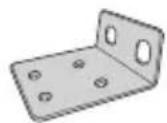
- Secure the mounting brackets to the two sides of the switch with eight M3 screws.
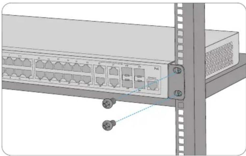
- Attach the switch to the rack using four M6 screws and cage nuts.
Grounding the Switch
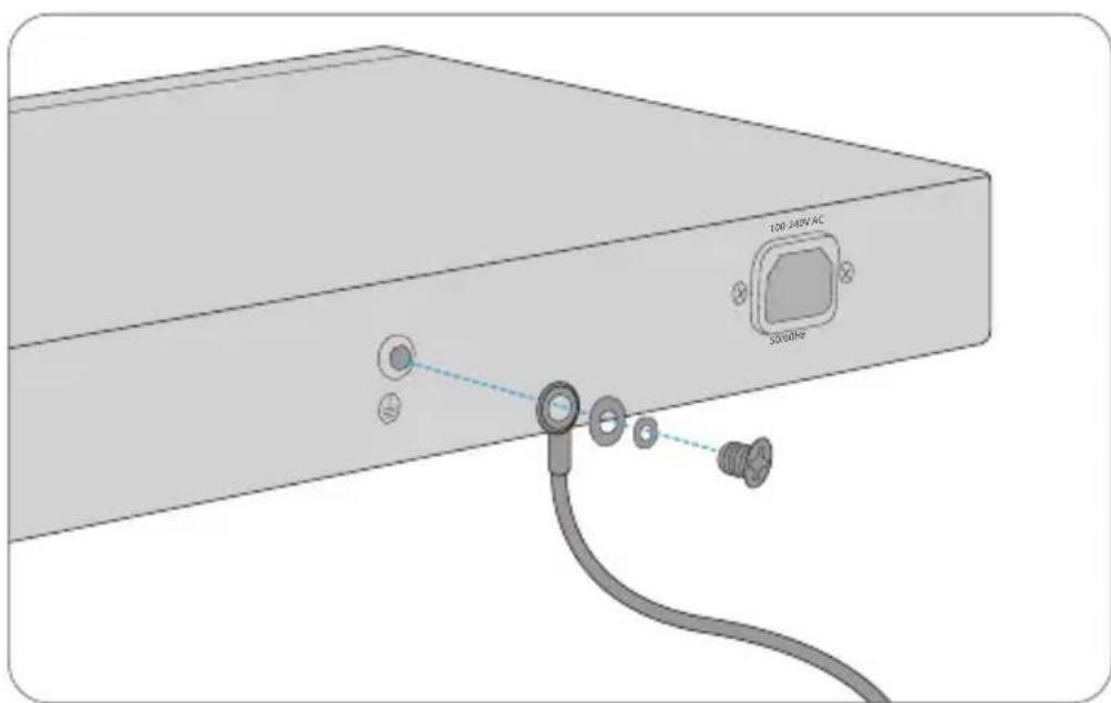
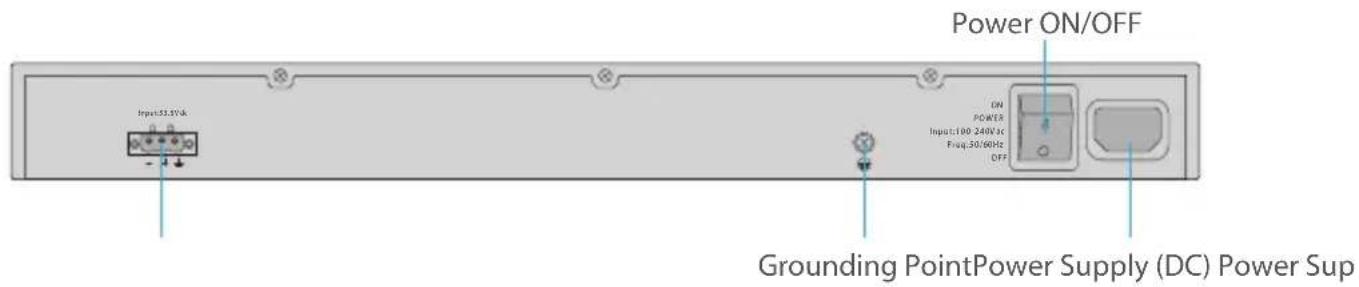
- Connect one end of the grounding cable to a proper earth ground, such as the rack in which the switch is mounted.
- Secure the grounding lug to the grounding point on the switch back panel with the washers and screws.

CAUTION: The earth connection must not be removed unless all supply connections have been disconnected.
Connecting the Power

- Plug the AC power cord into the power port on the back of the switch.
- Connect the other end of the power cord to an AC power source.

WARNING: Do not install power cables while the power is on.
Connecting the RJ45 Ports
natural_image
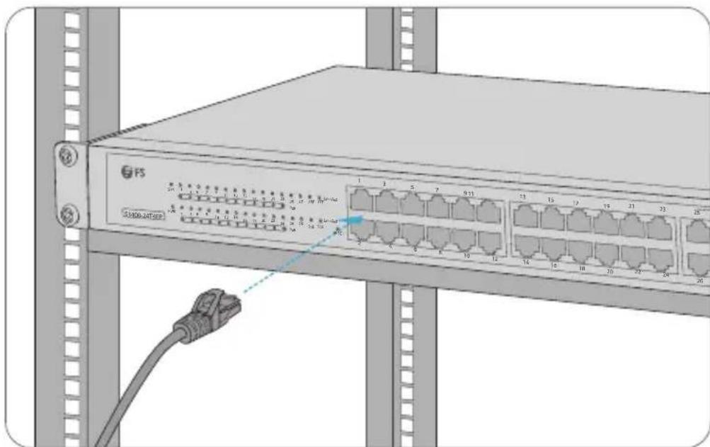
Diagram of a network switch device with labeled ports and connectors, showing connections between server racks (no readable text or symbols)- Connect an Ethernet cable to the RJ45 port of IP cameras, IP telephones, Access Points (AP), or other network devices.
- Connect the other end of the Ethernet cable to the RJ45 port of the switch.
Connecting the SFP/SFP+ Ports
-
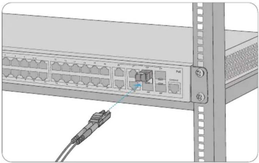
Plug the compatible SFP/SFP+ transceiver into the SFP/SFP+ port.
-
Connect a fiber optic cable to the fiber transceivers. Then connect the other end of the cable to other fiber devices.

WARNING: Laser beams will cause eye damage. Do not look into bores of optical modules or optical fibers without eye protection.
Connecting the Console Port

-
Insert the RJ45 connector of the console cable into the RJ45 console port on the front of the switch.
-
Connect the other end of the console cable to the RS-232 serial port on the computer.
Configuring the Switch
Configuring the Switch Using the Web-based Interface
Step 1: Connect the computer to any Ethernet port of the switch using the network cable.
Step 2: Set the IP address of the computer to 192.168.1.x. ("x" is any number from 2 to 254.). Set the subnet mask of the computer to 255.255.255.0.

Step 3: Open a browser, type http://192.168.1.1, and enter the default username and password, admin/admin.
Step 4: Click sign in to display the web-based configuration page.
Configuring the Switch Using the Console Port
Step 1: Connect a computer to the switch's console port using the supplied console cable.
Step 2: Start the terminal simulation software such as HyperTerminal on the computer.
Step 3: Set the parameters of the HyperTerminal: 115200 bits per second, 8 data bits, no parity, 1 stop bit and no flow control.
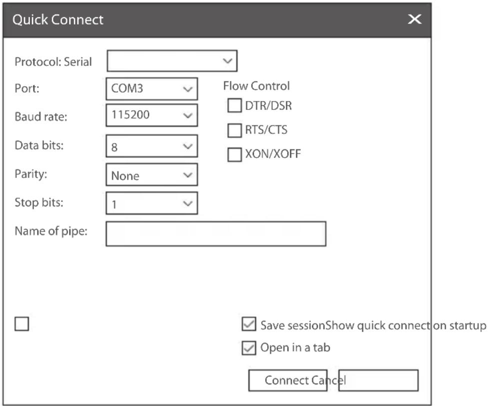
Step 4: Enter the default username and password, admin/admin.
Troubleshooting
Loading Failure Troubleshooting
After loading fails, the system will keep running in the original version. At this time, users should re-check if physical port connections are good firstly. If some ports are not connected, then re-connect them to ensure that physical connections are correct, and begin re-loading. If physical connections are correct, then check the loading process information displayed on the super terminal to verify if there are input errors. If there are input errors, correct them and re-load.
User Password Lost Troubleshooting
If the system password is lost or forgotten, the following method can be used to reset the password:
- Connect the console port of the switch to the
- Press ctrl + p to enter the Monitor# interface.
- Delete the configuration file to achieve reset.
monitor#delete startup-config
this file will be erased, are you sure?(y/n)y,
monitor#reboot
Do you want to reboot the Switch(y/n)?y

NOTE: Forgetting your username and password and restoring them through console port may cause configuration loss and business interruption. Please remember your username and password.
Configuration System Troubleshooting
- Make sure the power supply is normal and the console cable is properly connected.
- Check if the console cable is the right type.
- Check if the control cable driver is properly installed on the computer.
- Ensure the parameters of the HyperTerminal are correct.
Warranty
BZBGEAR wants to assure you peace of mind. We're so confident in the quality of our products that along with the manufacturer's one-year limited warranty, we are offering free second-year warranty coverage upon registration*.
Taking advantage of this program is simple, just follow the steps below:
- Register your product within 90 days of purchase by visiting BZBGEAR.com/warranty.
- Complete the registration form. Provide all necessary proof of purchase details, including serial number and a copy of your sales receipt.
For questions, please call 1.888.499.9906 or email support@bzbgear.com.
For complete warranty information, please visit BZBGEAR.com/warranty or scan the QR code below.

*Terms and conditions apply. Registration is required.
Mission Statement
BZBGEAR manifests from the competitive nature of the audiovisual industry to innovate while keeping the customer in mind. AV solutions can cost a pretty penny, and new technology only adds to it. We believe everyone deserves to see, hear, and feel the advancements made in today's AV world without having to break the bank. BZBGEAR is the solution for small to medium-sized applications requiring the latest professional products in AV.
We live in a DIY era where resources are abundant on the internet. With that in mind, our team offers system design consultation and expert tech support seven days a week for the products in our BZBGEAR catalog. You'll notice comparably lower prices with BZBGEAR solutions, but the quality of the products is on par with the top brands in the industry. The unparalleled support from our team is our way of showing we care for every one of our customers. Whether you're an integrator, home theater enthusiast, or a do-it-yourselfer, BZBGEAR offers the solutions to allow you to focus on your project and not your budget.
- 8/16/24/48-PORT GIGABIT L2+ POE+ MANAGED SWITCH
- Introduction
- Accessories
- Hardware Overview
- Front Panel Ports
- Front Panel Button
- Button Description
- Front Panel LEDs
- Back Panel
- Installation Requirements
- Before you begin the installation, make sure that you have the following:
- Site Environment:
- Mounting the Switch
- Desk Mounting
- Rack Mounting
- Grounding the Switch
- Connecting the Power
- Connecting the RJ45 Ports
- Connecting the SFP/SFP+ Ports
- Connecting the Console Port
- Configuring the Switch
- Configuring the Switch Using the Web-based Interface
- Configuring the Switch Using the Console Port
- Troubleshooting
- Loading Failure Troubleshooting
- User Password Lost Troubleshooting
- Configuration System Troubleshooting
- Warranty
- Mission Statement
Brand : BZBGear
Model : BG-FS8260
Category : Adapter