
PH460 - Unspecified BENQ - Free user manual and instructions
Find the device manual for free PH460 BENQ in PDF.


| Product Type | Professional LCD Display for Video Wall |
| Screen Size | 46 inches |
| Resolution | 1920 x 1080 (Full HD) |
| Brightness | 700 cd/m² (typical) |
| Contrast Ratio | 3500:1 (typical) |
| Viewing Angle | 178° / 178° |
| Video Inputs | HDMI, DVI, VGA |
| Control Interface | RS-232C (9-pin) |
| Color Calibration | Supported via Color Management software |
| Calibration Meter Support | X-Rite i1 Display Pro |
| Look-Up Table (LUT) | 10-bit per R/G/B |
| Calibration Targets | Color Temperature (6500K/9300K/11000K), Gamma (1.8/2.0/2.2/2.4), Brightness |
| Tiling Matrix Support | 1x1 to 10x10 |
| Power Consumption | 200 W (typical) |
| Standby Power | < 0.5 W |
| Dimensions (W x H x D) | 1054 x 608 x 100 mm (without stand) |
| Weight | 25 kg (without stand) |
| Operating Temperature | 0°C to 40°C |
| Mounting | VESA 400 x 400 mm |
| Repairability | User-accessible parts: power supply, main board; professional service required for panel |
| Compatible Operating Systems | Windows XP, Vista, 7 (32/64-bit) |
Frequently Asked Questions - PH460 BENQ
User questions about PH460 BENQ
0 question about this device. Answer the ones you know or ask your own.
Ask a new question about this device
Download the instructions for your Unspecified in PDF format for free! Find your manual PH460 - BENQ and take your electronic device back in hand. On this page are published all the documents necessary for the use of your device. PH460 by BENQ.
USER MANUAL PH460 BENQ
natural_image
Abstract grayscale pattern with concentric dotted and solid bands, no text or symbols presentDisclaimer
BenQ Corporation makes no representations or warranties, either expressed or implied, with respect to the contents of this document. BenQ Corporation reserves the right to revise this publication and to make changes from time to time in the contents thereof without obligation to notify any person of such revision or changes.
Copyright
Copyright 2013 BenQ Corporation. All rights reserved. No part of this publication may be reproduced, transmitted, transcribed, stored in a retrieval system or translated into any language or computer language, in any form or by any means, electronic, mechanical, magnetic, optical, chemical, manual or otherwise, without the prior written permission of BenQ Corporation.
Table of Contents
Disclaimer 2
Copyright......2
Introduction ......4
Key features ....4
System requirements .... 4
Calibration overview ....5
Calibration workflow....5
Calibration target....5
Preparations....7
Installing Color Management....7
Connecting the color meter 7
Connecting display(s) to the computer 7
Setting monitor ID....8
Warming-up the display(s)......8
Using the Color Management ......9
Performing calibration - a quick guide 9
Overview of components and functions......16
Menu bar....16
File menu....16
Tools menu....16
Settings menu....17
About menu....17
Control panel....18
Display Wall tab 18
Advance tab....19
Status panel....22
Troubleshooting....23
Error message....24
Introduction
The uniformity in image representation is a vital element in creating a video wall that consists of multiple displays. However, due to factors like component variation and aging, it is inevitable for each display to produce images with slight differences in color and luminance even when related settings are identical among all displays.
The Color Management is designed to minimize such differences and enhance the image uniformity of all displays in a video wall application. It works by first measuring and comparing the color characteristics of each display, and then calibrating all displays with a common and optimal setting.
With the Color Management, you can also adjust color settings of each display easily on a host computer, or backup and restore calibration data quickly.
Key features
The Color Management provides the following functions and features:
• Supported calibration targets:
- Color temperature (6500K/9300K/11000K)
- Gamma (1.8/2.0/2.2/2.4)
- Brightness (backlight luminance)
Refer to page 5 for more information about the calibration targets.
- Supported display tiling matrix: 1x1\~10x10
- Supported display parameter: 10 bits LUT (Look Up Table) for R/G/B
- Supported internal test pattern: 256 R/G/B/W levels
- Accuracy: Delta_x, Delta_y < ±0.5% with (1) DVI source for 30%\~80% white level and (2) IID3 measurement
• Colorimeter that displays the color meter measurement values - Local backup and restore functions that makes it easy to save and restore LUT and R/G/B gain settings
- Manual adjustment functions (brightness, contrast, R/G/B gain and offset) that allow fine-tuning of individual display
System requirements
The following items are required to use the Color Management.
- A color meter (supported model: X-Rite iI Display Pro)
- A host computer (PC) that meets the following minimum hardware and software requirements:
| CPU Pentium 1GHz | |
| Free memory | GB | |
| Hard disk space 400 MB | |
| Operating system Windows XP (32-bit/64-bit), Windows Server 2003,Windows Vista (32-bit/64-bit) or Windows 7 (32-bit/64-bit) | |
| RS-232 port An available | RS-232 port |
| HDMI/DVI/VGA port | An available HDMI, DVI or VGA output port |
• HDMI, DVI or VGA cable and RS-232 cable

The firmware version of the PH and PL series displays must be V1.06 or higher to work with the Color Management.
Calibration overview
Calibration workflow
The diagram below lists the basic workflow for performing calibration using the Color Management for the first time. If this is not the first time you use Color Management to calibrate the displays, you can start from step 2 directly.
Step I: Install Color Management on a host PC (see page 7)

Step 2: Connect the color meter to the PC (see page 7)

Step 3: Connect the PC to the display(s) via RS-232 connection (see page 7)

Step 4: Set monitor ID on each display (see page 8)

Step 5: Open the Color Management and perform calibration (see page 9)
Calibration target
The Color Management calibrates displays by measuring, adjusting and synchronizing the following settings:
Color temperature
There are many different shades that are considered to be "white" for various purposes. One of the common methods of representing the white color is known as the "color temperature". A white color with a low color temperature appears to be reddish white, while a white color with a high color temperature appears to have more blue in it.
The Color Management allows you to set a different color temperature as calibration target. However, if the selected color temperature is very different from the native one, a large correction must be applied and the maximum brightness will be affected.
Gamma
The gamma of a display is the relationship between the video input signal and the light output (“brightness”). The display is a nonlinear device. Doubling the level of the video input signal to the display does not double the light output.
A gamma value of I would result in a perfectly linear display (doubling the signal level doubles the light output). You can use the Color Management to choose a different gamma target for all displays.
Brightness
The Color Management provides options for brightness adjustment with which you can change the display's screen brightness level and synchronize it among multiple displays. According to the number of display(s) and your Brightness setting when the calibration project starts, the calibration method differs:
- If a single display is being calibrated, the display's brightness will be calibrated to your Brightness setting.

The tolerance of the target brightness is ± 15 nits.
- If multiple displays are being calibrated and all connected to the computer:
- When Brightness is set to Auto, the Color Management will synchronize the brightness level of all displays with that of the darkest display. The principle is illustrated as follows:
Before brightness calibration After brightness calibration
| 440 | 430 | 435 |  | 430 | 430 | 430 |
| 435 | 450 | 440 | 430 | 430 | 430 | |
| 445 | 430 | 450 | 430 | 430 | 430 |
Brightest display: brightness level = 450
Darkest display: brightness level = 430
However, if any of the displays' actual brightness level (as measured by the color meter) fails to meet the darkest brightness level (as read from the internal memories of all displays), the Color Management will re-synchronize the brightness level of all displays to the actual darkest brightness level.
- When Brightness is set to other settings than Auto, the Color Management will adjust the brightness level of all displays to the target brightness setting. If any display fails to reach the target brightness due to various factors like hardware limitations and component deterioration, a warning message will appear.
- If multiple displays are being calibrated but some of them are disconnected from the computer, a warning message will appear. In this case, brightness synchronization will not be performed by the Color Management.
Preparations
The following operations must be performed before you can use the Color Management to calibrate your display(s).
Installing Color Management
Ensure that the computer meets the minimum system requirements set forth on page 4.
I. Locate the Setup.exe file and double-click it to begin installation.
2. Follow the on-screen instructions to complete the installation.

To run Color Management in Windows 7, the User Access Control (UAC) must be temporarily disabled. To disable UAC:
I. From the Start menu, select Control Panel > User Accounts and Family Safety > User Account.
2. Click on the User Account Control settings link, and then drag the slider bar to the lowest value (towards Never Notify).
3. Click OK and restart the computer to make the change effective.
Connecting the color meter
Follow the instructions provided in the documentations of the color meter to connect it to the computer, and complete its hardware and software setup if necessary.
Connecting display(s) to the computer
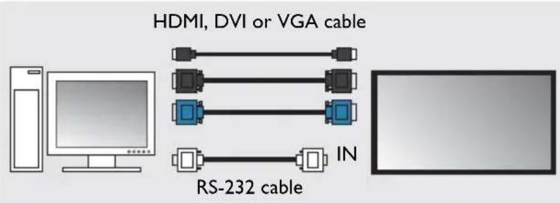
HDMI/DVI/VGA input and RS-232C serial connections between the display and computer are required to transmit control signals. The diagram below shows the general connection schemes. For details on the location of ports and connectors, please refer to the documentations of the computer and display.
Single-display connection
Multiple-display connection

flowchart
graph LR
    A["Computer"] --> B["HDMI, DVI or VGA cable"]
    B --> C["RS-232 cable"]
    C --> D["Output"]
    C --> E["RS-232 cable"]
    E --> F["In"]
    E --> G["OUT"]
    G --> H["RS-232 cable"]
    H --> I["In"]
Setting monitor ID
For the Color Management to calibrate multiple displays, each display must be assigned an unique monitor ID. Otherwise the display(s) will not be identified correctly.
To assign monitor ID on each display, open the OSD menu of the display and select Settings > Set Monitor ID.

Be sure to assign a unique monitor ID for each display.
Warming-up the display(s)
For a precise calibration result, the power-on time of the display(s) to be calibrated must be longer than 60 minutes before calibration.
Using the Color Management
Performing calibration - a quick guide
This section provides a quick guide that walks you though the basic calibration procedures by creating a new calibration project.

- For detailed information about the components and functions of the Color Management, please refer to "Overview of components and functions" on page 16.
- Before you start, make sure that you have completed the initial preparations as described in "Preparations" on page 7.
I. Launch the Color Management by clicking Windows Start button and selecting Programs >Color Management. You can also double-click the Color Management icon on Windows Desktop to launch the program. The Color Management main screen appears.
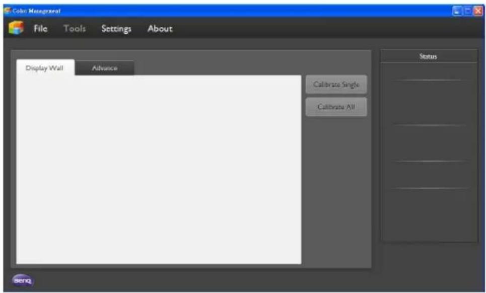

Be sure to reset all color settings before proceeding to the next step. Please refer to page 21 for more information.
- Click File > New project to create a new project. The Create Project dialog appears.
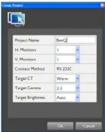
- Refer to the table below to set the parameters and click OK when finished.

Once a project is created, the parameters cannot be changed. You need to create another new project if you want to change these settings.
| Option/Setting Description/Instruction | |
| Project Name Enter a project name for the calibration task. | |
| H. Monitors (number of displays on the horizontal side) | Sets the number of displays to be calibrated.If you are calibrating a single display, select 1 in both H.Monitors and V. Monitors.If you are calibrating multiple displays in a display wall, set the number of displays in H. Monitors and V. Monitors.For example:6 monitors 12 monitors |
| V.Monitors (number of displays on the vertical side) |  H. Monitors = 2V. Monitors = 3 H. Monitors = 2V. Monitors = 3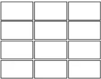 H. Monitors = 3V. Monitors = 4 H. Monitors = 3V. Monitors = 4 |
| Connect Method Displays the connection method: RS-232C. | |
| Target CT Sets the target color temperature. | |
| Target Gamma Sets the target gamma. | |
| Target Brightness Sets the target brightness. | |
-
According to the number of display(s) you wish to calibrate, there are 2 calibration scenarios:
-
Single-display calibration: refer to "Calibrating a single display" on page 11 for the next step.
- Multiple-display calibration: refer to "Calibrating a multiple displays" on page 13 for the next step.
Calibrating a single display
I. Click to select the display box that represents the display you want to calibrate on the Display Wall tab, and then click Calibrate Single.


- In the Color Management, each display is represented by a display box on the Display Wall tab. For more information about the display box, refer to "Display Wall tab" on page 18.
- If the display is connected to the computer successfully, the "connected" icon appears on the upper right corner of the display box. If the "disconnected" icon appears, refer to "Troubleshooting" on page 23 for how to solve the connection problem.
- The power-on time of the display must be longer than 60 minutes before calibration. Otherwise a dialog asking you warm-up the display will appear after you click the Calibrate Single button.

Display box
- The calibration window appears. Click Run to proceed.
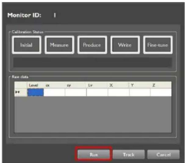

You can also click Track to measure the CIE1931 (x,y) values of current W,R,G and B colors at level 255 for further analysis.
- You will be requested to put the color meter in the center of the display's screen. A center pattern is displayed on the screen for alignment at the same time. Click Yes.


- The calibration starts, and the status will be indicated in the Calibration Status area.

- Initial: The computer is validating connection to the display and color meter.
- Measure: The color meter is measuring the display's color profile.
- Produce: The Color Management is calculating for optimal values.
- Write: The Color Management is transmitting the updated Look Up Table (LUT) to the display.
- Fine-tune: The Color Management is fine-tuning the backlight.

During calibration, do not change the position of the color meter, move the display to another location or change display settings. Otherwise the precision of calibration will be affected.
- When calibration is completed, the status bar of the display box changes from "Not Calibrated" to "Calibrated", and its color becomes green. The x and y values of the W/R/G/B colors will also appear in the box.

Now you have successfully calibrated the display.

You can fine-tune the calibration result manually using the Manual Adjust tool. Refer to "Manual Adjust tool" on page 21 for more information.
Calibrating a multiple displays
I. Click Calibrate All on the Display Wall tab.


- In the Color Management, each display is represented by a display box on the Display Wall tab. For more information about the display box, refer to "Display Wall tab" on page 18.
- If the display is connected to the computer successfully, the "connected" icon appears on the upper right corner of the display box. If the disconnected icon appears, refer to "Troubleshooting" on page 23 for how to solve the connection problem.
- The power-on time of the displays must be longer than 60 minutes before calibration. Otherwise a dialog asking you warm-up the displays will appear after you click the Calibrate All button.

Display box
- The Select first calibration dialog follows. Click to select the ID of the first display to be calibrated and then click Set.
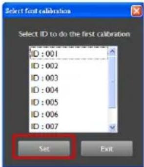
- The calibration window appears. Click Run to proceed.
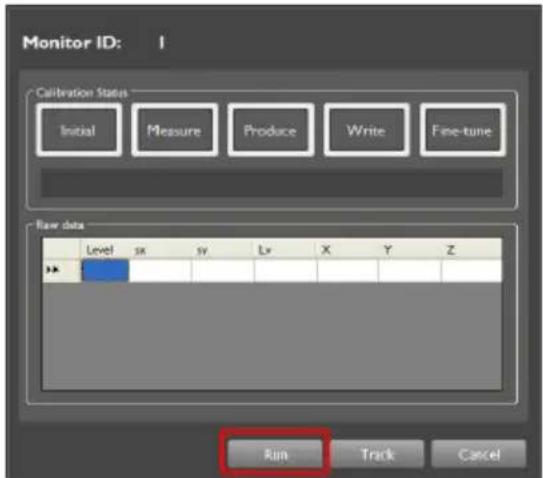

You can also click Track to measure the CIE1931 (x,y) values of current W,R,G and B colors at level 255 for further analysis.
- You will be requested to put the color meter in the center of the display's screen. A center pattern is displayed on the screen for alignment at the same time. Click Yes.


- The calibration starts, and the status will be indicated in the Calibration Status area.

- Initial: The computer is validating connection to the display and color meter.
- Measure: The color meter is measuring the display's color profile.
- Produce: The Color Management is calculating for optimal values.
- Write: The Color Management is transmitting the updated Look Up Table (LUT) to the display.
- Fine-tune: The Color Management is fine-tuning the backlight.

During calibration, do not change the position of the color meter, move the display to another location or change display settings. Otherwise the precision of calibration will be affected.
-
A dialog requesting you to move the color meter to the next display (current display ID + 1) appears. Repeat step 4 and step 5 to complete calibration for all displays.
-
The Color Management will calibrate and adjust all displays to the same color and backlight level. When calibration is completed, the status bar of the display boxes changes from "Not Calibrated" to "Calibrated", and its color becomes green. The x and y values of the W/R/G/B colors will also appear in the boxes.

Now you have successfully calibrated all displays.

You can fine-tune the calibration result manually using the Manual Adjust tool. Refer to "Manual Adjust tool" on page 21 for more information.
Overview of components and functions
The Color Management main screen consists of the following components:
I. Menu bar
2. Control panel
3. Status panel

Menu bar
File Tools Settings About
File menu
| Option/Setting Description | |
| New project | Creates a new calibration project. A dialogue appears for you to set up calibration parameters. |
| Open project Opens | an existing calibration project file (*.vns file). |
| Save | Saves current calibration project file. By default, the project will be saved as a *.vns file in the same folder where the Color Management program files are located. (For example, C:/ Program Files/Color Management/) |
| Save As Saves current | calibration project as another new project file. |
| Exit Closes and exits | the Color Management. |
Tools menu
| Option/Setting Description | |
| Backup | Saves the LUT values and backlight settings of a display as a backup file. (*.lut file)Click to select a display (display box) on the Display Wall tab and select this option. By default, the backup file will be named following the format below:ProjectName_SSerialNumber_MMonitorID_CTTargetCT_GTargetGamma.lut |
| Restore | Loads (restores) the LUT values and backlight settings of a display from a backup file. (*.lut file)Click to select a display (display box) on the Display Wall tab and select this option. You need to connect a color meter to the computer before loading the backup file. |
Settings menu
| Option/Setting Description | ||
| Connection | Selects a COM port that is used for RS-232C connection.To select a COM port:1. Click to select a COM port from theComPort drop-down box.  2. To apply the COM port setting to current display, selectSingle. SelectAll if you want to apply the COM port setting to all displays.3. ClickConnectto establish RS-232C connection to the display(s). 2. To apply the COM port setting to current display, selectSingle. SelectAll if you want to apply the COM port setting to all displays.3. ClickConnectto establish RS-232C connection to the display(s). | |
| Color meter | If there are multiple color meters connected to the computer, you can use this function to select the color meter to use for calibration. | |
| Center pattern | Selects and displays a center pattern on the screen for color meter installation.To select a center pattern:1. Click to select a pattern.2. To display center pattern on the screen of current display, selectSingle. SelectAll if you want to display center pattern on the screens of all displays.3. ClickSetto confirm. |  |
| The center pattern will not disappear from the display's screen when you close the Color Calibration Tool. To close the center pattern, restart the display. | ||
| Language Selects a preferred language for the Color Management. | ||
About menu
| Option/Setting Description | |
| About | Displays the software version and other information about the Color Management. |
Control panel
Display Wall tab

The Display Wall tab allows you to view the status and color settings of all displays connected to the computer. Each display is represented by a display box, and the number and layout of the display boxes on the Display Wall tab correspond to the Tile Matrix setting when you create the calibration project.
Please refer to the description below for the information provided in a display box.

other
| | x | y | |---|---|---| | W | 0.312 | 0.326 | | R | 0.626 | 0.326 | | G | 0.283 | 0.598 | | B | 0.148 | 0.048 |I. Monitor ID: Shows the ID of the display that is set in the display's OSD menu.
2. Status: Shows the calibration status of the display: Not Calibrated or Calibrated.
3. X and Y values: displays the x and y values of White/Red/Green/Blue colors after the display is calibrated.
4. Connection status: Indicates the status of connection.
- : the display is connected to the computer
- the display is disconnected from the computer.
Advance tab
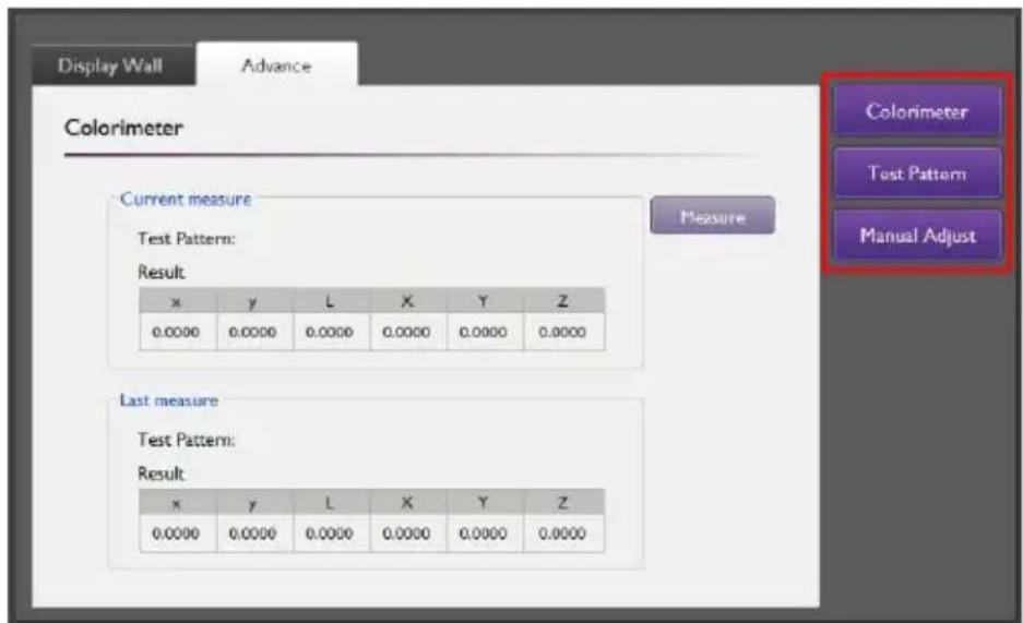
The Advance tab provides tools and options that allow you to view and manually adjust color settings of the display selected on the Display Wall tab.
Click a function button beside the tab to switch to a different function.
Colorimeter tool
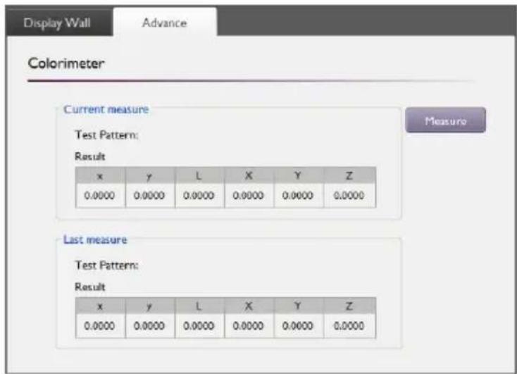
The Colorimeter tool shows the results measured by the color meter after you calibrate the display. You can click the Measure button to manually perform measurement again.

- Use the Center Pattern function in the Settings menu to display center pattern on the display's screen before you perform measurement.
- The center pattern will not disappear from the display's screen when you close the Color Calibration Tool. To close the center pattern, restart the display.
Test Pattern tool

The Test Pattern tool allows you to display test patterns on the display's screen for verifying color uniformity. To display a test pattern:
I. Click to select a test pattern.
-
Click to select a color temperature setting from the Color Temperature box (optional).
-
Specify the color level (0\~255) of the test pattern in the Level box (optional).
-
To display test pattern on the screen of current selected display, select Single. Select All if you want to display test pattern on the screens of all displays.
-
Click Set.

- It is recommended that you set the display's Picture Mode setting to Standard before using the test pattern.
- The test pattern will not disappear from the display's screen when you close the Color Calibration Tool. To close the test pattern, restart the display.
Manual Adjust tool

The Manual Adjust tool allows you to manually fine-tune color settings after calibration.
To manually fine-tune color settings:
I. Click the radio button of a color setting. For example, the Gain radio button of Red.
2. Enter the desired value in the Adjust box.
3. Repeat step 1 and 2 to fine tune the settings of other colors.
4. Click Set. The settings will be applied and the measured values will appear in the table on the left of the Adjust box. If you want to apply color settings without performing measurement, check the Without measurement checkbox before clicking Set.

- For the adjustments you performed using the Manual Adjust tool to take effect, you need to restart the display.
- Be sure to reset all color settings by clicking the Set default button before performing a new calibration.
Status panel
The Status panel indicates the status and provides detailed information about the display selected on the Display Wall tab.
| Status | |
| Project Name | BenQ |
| H. Monitors | 2 |
| V. Monitors | 1 |
| Monitor ID | 2 |
| Model | PL460 |
| Connection | RS-232C |
| ComPort | COMI |
| Connect Status | True |
| Meter Type | iID3 |
| Meter Status | Close |
| Target CT | Warm |
| Target Gamma | 2.2 |
| Target Brightness | Auto |
| Video Source | External |
| Project Status | Not Calibrated |
| Item Description | |
| Project Name Current project file name. | |
| H. Monitors Number of displays on the horizontal side. | |
| V. Monitors Number of displays on the vertical side. | |
| Monitor ID The ID of the selected display. | |
| Model Model name of the display. | |
| Connection Connection method: RS-232C. | |
| ComPort | Number of the COM port currently being used for RS-232C connection. |
| Connect Status Current connection status. | |
| Meter Type Model name of the color meter connected to the computer. | |
| Meter Status | Connection status between the color meter and the computer. |
| Target CT | Value of the target color temperature setting. |
| Target Gamma | Value of the target gamma setting. |
| Target Brightness | Value of the target brightness setting. |
| Video Source | Video source being used for calibration.• Internal: The display is currently using the White, Red, Green, or Blue test pattern for calibration.• External: The display is currently using the External test pattern for calibration. |
| Project Status | Status of calibration. |
Troubleshooting
If you encounter problems during calibration, please refer to the following troubleshooting tips to try to solve the problems by yourself. If the problem persists, please contact BenQ Customer Support for help.
| Problem Solution | |
| Cannot connect to the display(s) | Check the following:Check the cable connection. Is the display correctly connected to the computer?Is the display turned on?Is the COM port setting in Settings menu > Connection correct? |
| The display is not on the Display Wall tab | Check the display's ID setting. When calibrating multiple displays, each display must be given an unique ID for the Color Management to identify correctly. |
Error message
If an error occurs, an error message dialog will pop up on the screen. Refer to the table below for the information about the error messages.
| Class Function Error code | ||
| Setting | RS-232 RS-232 - | |
| iId3 iId3 - | ||
| Calibration | initial C10x | |
| adjust BL C12x | ||
| measure raw data C20x | ||
| produce LUT C30x | ||
| write LUT C40x | ||
| adjust LUT C50x | ||
| tracking C52x | ||
| Project | New P10x | |
| Load P20x | ||
| Save P30x | ||
| Save as P40x | ||
| Tool | Backup T10x | |
| Restore T20x | ||
| Advance | Colorimeter | A10x |
| Test pattern | A20x | |
| Manual adjust | A30x | |
| Others | Others | O10x |
- Disclaimer
- Copyright
- Table of Contents
- Disclaimer 2
- Copyright......2
- Introduction ......4
- Calibration overview ....5
- Preparations....7
- Using the Color Management ......9
- Overview of components and functions......16
- Troubleshooting....23
- Error message....24
- Introduction
- Key features
- System requirements
- Calibration overview
- Calibration workflow
- Calibration target
- Color temperature
- Gamma
- Brightness
- Preparations
- Installing Color Management
- Connecting the color meter
- Connecting display(s) to the computer
- Setting monitor ID
- Warming-up the display(s)
- Using the Color Management
- Performing calibration - a quick guide
- Calibrating a single display
- Calibrating a multiple displays
- Click Calibrate All on the Display Wall tab.
- Overview of components and functions
- Menu bar
- File menu
- Tools menu
- Control panel
- Display Wall tab
- Advance tab
- Colorimeter tool
- Test Pattern tool
- Manual Adjust tool
- Status panel
- Troubleshooting
- Error message
Brand : BENQ
Model : PH460
Category : Unspecified