
Profile DISQ493DTWW - Coffee maker GE - Free user manual and instructions
Find the device manual for free Profile DISQ493DTWW GE in PDF.


| Product Type | Electric Dryer |
| Brand | GE |
| Model | Profile DISQ493DTWW |
| Installation Type | Freestanding, alcove or closet compatible |
| Exhaust Type | Rear, side, or bottom exhaust (convertible) |
| Exhaust Duct Required | 100 mm (4 in) rigid or flexible metal duct |
| Electrical Connection | Terminal block or power cord; 240 V, 30 A, 60 Hz (typical) |
| Power Cord | Not included; must be purchased separately (NEMA 14-30R recommended) |
| Minimum Clearances | 0 mm sides; 80 mm front and rear; 1.3 m vertical |
| Door | Removable for service or disposal |
| Control Console Location | Wiring diagram and service information inside control console |
| Approximate Dimensions (H x W x D) | 36 x 27 x 29 in (91 x 69 x 74 cm) |
| Approximate Weight | 120 lb (54 kg) |
| Included Accessories | Literature package, installation instructions |
| Required Tools | Screwdrivers, slip joint pliers, level, duct tape |
| Safety Features | Grounding required; no extension cord allowed; do not use plastic duct |
| Warranty | Standard GE warranty (refer to owner's manual) |
Frequently Asked Questions - Profile DISQ493DTWW GE
User questions about Profile DISQ493DTWW GE
0 question about this device. Answer the ones you know or ask your own.
Ask a new question about this device
Download the instructions for your Coffee maker in PDF format for free! Find your manual Profile DISQ493DTWW - GE and take your electronic device back in hand. On this page are published all the documents necessary for the use of your device. Profile DISQ493DTWW by GE.
USER MANUAL Profile DISQ493DTWW GE
Installation instructions for your new
Electric Dryer
Before you begin - Read these instructions completely and carefully.
IMPORTANT - Save these instructions for local inspector's use.
IMPORTANT - OBSERVE ALL GOVERNING CODES AND ORDINANCES.
Note to Installer - Be sure to leave these instructions with the Consumer.
Note to Consumer - Keep these instructions with your Owner's Manual for future reference.
31
Note: Installation of this dryer requires basic mechanical and electrical skills.
It is your responsibility to contact a qualified electrical installer to make the electrical connection.

WARNING – POTENTIAL FIRE AND SHOCK HAZARD
- Use only rigid or flexible metal 100mm (4") diameter ductwork for exhausting to the outdoors. Never use plastic or other combustible ductwork.
- This appliance must be properly grounded (earthed) and installed as described in these instructions and governing codes.
- Do not install or store appliance in an area where it will be exposed to water/weather.
Important
- Exhausting the dryer to the outdoors is strongly recommended to prevent large amounts of moisture and lint from being blown into the room.
- Before the old dryer is removed from service or discarded, remove the door to the drying compartment.
- Service information and wiring diagram are located in control console.
Tools and Materials you will need
- Slip joint pliers
- Screwdrivers (slotted or Phillips head)
• One 3/4" recognized strain relief - 4 inch dia. rigid metal duct, elbows and exhaust hood.
- Basic safety protection such as safety goggles, gloves, and arm protection is recommended.
Installation
Step 1
Remove and save literature and parts package from dryer drum.
Step 2
Lay carton corner posts or two boards on floor. Lay dryer on its back.
Step 3
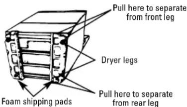
Remove foam
shipping pads by
pulling at sides and breaking away from dryer legs. Be sure to remove all foam pieces from around legs.
Step 4
Stand dryer upright.
Step 5
Move dryer to desired operating location.
Step 6
Adjust leveling legs to match washer height. Dryer must be level and rest firmly on all four leveling legs.
Step 7
Connect to power supply.
(See ELECTRICAL CONNECTION INFORMATION section of this instruction.)
Step 8
Connect external exhaust or deflector. (See EXHAUST INFORMATION section of this instruction.)
Step 9
Check for proper operation.
Step 10
Place Owner's Manual and installation instructions in a location where they may be found by the customer.
Electrical Connection Information
A WARNING: TO REDUCE THE RISK OF FIRE, ELECTRIC SHOCK, OR PERSONAL INJURY
- DO NOT USE AN EXTENSION CORD WITH THIS APPLIANCE.
- THIS APPLIANCE MUST BE PROPERLY GROUNDED (EARTHED).
Dryer must be electrically grounded (earthed) in accordance with local codes and ordinances.
Electrical requirements:
- The operating voltage (volts), amperage (amps) or wattage (watts) and frequency (Hz) of your dryer are indicated on the rating plate located on the upper right corner of the door opening.
- The dryer must be connected to an individual branch circuit corresponding to that indicated on the rating plate and protected by the required time-delay fuses or circuit breakers in accordance with governing codes.
- If the electrical supply does not meet what is indicated on the rating plate, call a licensed electrician.
IF THE DRYER IS SUPPLIED WITH A FLEXIBLE POWER CORD
Plug the cordset into its own separate grounded outlet. DO NOT, UNDER ANY CIRCUMSTANCES, CUT OR REMOVE THE GROUND PRONG FROM THE POWER CORD.
IF THE DRYER IS SUPPLIED WITH A TERMINAL BLOCK

WIRING DIAGRAM AND SOME SERVICE INFORMATION LOCATED IN CONTROL HOUSING
- Remove cover near the power supply entry hole.
- Install 3/4 inch, recognized strain relief to power entry hole. Bring power supply through strain relief.
-
Connect power supply as follows:
A. Live (brown) line to upper screw of terminal block (marked L1).
B. Neutral (blue) line to center screw of terminal block (marked N). -
Attach ground (earth) wire (green, green and yellow, or bare) to the green ground screw (hole above strain relief bracket). Tighten all terminal block screws firmly.
-
Properly secure power supply to strain relief.
-
Reinstall the cover.
WARNING: NEVER LEAVE THE TERMINAL BLOCK WITHOUT THE COVER.
Exhaust Information
WARNING: TO REDUCE THE RISK OF FIRE AND PERSONAL INJURY
- Use only metal duct for exhausting dryer to outdoors.
- Do not terminate exhaust in a chimney, any gas vent, under an enclosed floor (crawl space), or into an attic. The accumulated lint could create a fire hazard.
- Provide an access for inspection and cleaning of the exhaust system, especially at turns. Inspect and clean at least once per year.
- Never terminate the exhaust into a common duct with a kitchen exhaust. A combination of lint and grease could create a fire hazard.
- Do not obstruct incoming or exhausted air.
Rear Exhaust Location
This dryer comes ready for rear exhausting. If space is limited, use the following instructions to exhaust directly from the side or bottom of the cabinet.

0 mm (3½")
NOTE: Add to vertical dimension the distance between cabinet bottom and floor surface.
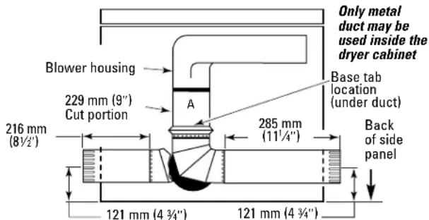
Steps to Change Dryer to Side or Bottom Exhaust Directly on Cabinet
WARNING: Protect your hands and arms from sharp edges when working inside the dryer cabinet.
-
Detach and remove the desired knockout.
-
Remove the screw inside the dryer exhaust duct end. Keep the screw for step 5. Pull on the duct to remove it.

-
Cut the duct as shown. Keep portion A.
-
Through the rear opening, locate the tab in the middle of the dryer base. Lift the tab to about 45° using a flat screwdriver.
-
Reconnect and secure the cut portion (A) of the duct to the blower housing. Make sure the fixing hole is aligned with the tab in the base. Use the screw from step 2 to secure the duct in place through the tab on the dryer base.
-
Use standard metal elbows and duct to complete the exhaust system. Insert standard elbows and ducts through rear and side or bottom openings.
-
Cover the opening at the back with the plate (Kit WE1M454) available from your local service provider. WARNING: NEVER LEAVE THE BACK OPENING WITHOUT THE PLATE.
Exhaust Length
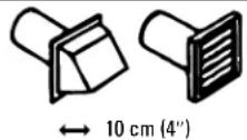
The MAXIMUM ALLOWABLE length of the exhaust system depends upon the type of duct, number of turns, type of exhaust hood (wall cap) and all conditions noted below. The maximum allowable length for both rigid and flexible metal duct is shown in the table below. More than two 90° turns are not recommended.
| FOR ELECTRICDRYER ONLY | RECOMMENDED MAXIMUM LENGTH | ||
| Weather Hood Type | |||
| Recommended | Use only forshort runinstallations | ||
 |  | ||
| Number of90° elbows | Rigid Flexible Metal | Metal | |
| 0 10.7m (35 ft) | 7.6m (25 ft) 7.6m (25 ft) 4.0m (3 ft) | ||
| 1 9.1m (30 ft) | 4.6m (15 ft) 4.6m (15 ft) 3.0m (10 ft) | ||
| 2 6.1m (20 ft) | 3.0m (10 ft) 3.0m (10 ft) | ||
- Do not use non-metallic flexible duct.
Hood or Wall Cap
- Terminate in a manner to prevent back drafts or entry of birds or other wildlife.
- Termination should present minimal resistance to the exhaust airflow and should require little or no maintenance to prevent clogging.
- Never install screen over exhaust duct.
- Wall caps must be installed at least 300 mm (12") above ground level or any other obstruction with the opening pointed down.
- If roof vents or louvered plenums are used, they must be equivalent to a 100 mm (4") dampered wall cap in regard to resistance to airflow, prevention of back drafts and maintenance required to prevent clogging.
Separation of Turns
For best performance, separate all turns by at least 1.2 m (4') of straight duct, including distance between last turn and dampered wall cap.
Turns Other Than 90°
• One turn of 45° or less may be ignored.
- Two 45° turns should be treated as one 90° .
• Each turn over 45° should be treated as one 90° .
Sealing of Joints
- All joints should be tight to avoid leaks. The male end of each section of duct must point away from the dryer.
- Do not assemble the duct work with fasteners that extend into the duct. They will serve as a collection point for lint.
- Duct joints can be made air- and moisture-tight by wrapping the overlapped joints with duct tape.
Exhaust Information (cont.)
Insulation
- Ductwork which runs through an unheated area or is near an air-conditioning duct should be insulated to reduce condensation and lint buildup.
Parts Available From Local Service Organization
• Rigid Metal Duct Components
WX8X64 100 mm (4") x 60 cm (2') Duct
WX8X51 100 mm (4") Elbow
WX8X88 100 mm (4") Aluminum Hood
WE25X28 Exhaust Deflector
- Flexible Metal Duct Components
Kit WX8X75 2.1 m (7') Aluminum Flexible Duct
100 mm (4") Clamps (2)
100 mm (4") Aluminum Hood
Inside Exhausting
BEDROOM, BATHROOM, ALCOVE, OR CLOSET INSTALLATIONS MUST BE EXHAUSTED TO THE OUTDOORS.
EXHAUSTING TO THE OUTDOORS IS STRONGLY RECOMMENDED. EXHAUSTING INDOORS MAY CAUSE LINT ACCUMULATION AND MOISTURE DAMAGE INCLUDING MOLD AND MILDEW.
If the installation makes it impossible to exhaust to the outdoors, a 100 mm (4") exhaust deflector (WE25X28) and 600 mm (2') rigid metal duct (WX8X64) must be installed over exhaust duct. A clearance of 200 mm (8") is required between rear of dryer and the wall, and the deflector should be pointing up.

Special Installation Requirements
Alcove or Closet Installation
- If your dryer is approved for installation in an alcove or closet it will be stated on a label on the dryer back.
- The dryer must be exhausted to the outdoors.
- Minimum clearances between dryer cabinet and adjacent walls or other combustible surfaces are:
0 mm clearance on either side
80 mm (3") front and rear
- Minimum vertical space from floor to overhead cabinets, ceilings, etc. is 1.3 m (52").
- Closet doors must be louvered or otherwise ventilated and must contain at least 400cm2 (60 square inches) open area equally distributed. If this closet contains both a washer and a dryer, doors must contain 800cm2 (120 square inches) of open space equally distributed.
SERVICING:
Consideration must be given to provide adequate clearances for installation and servicing.

CAUTION:
Label all wires prior to disconnection when servicing controls. Wiring errors can cause improper and dangerous operation (verify proper operation after servicing/installation).





- INSTALLATION INSTRUCTIONS FOR YOUR NEW
- ELECTRIC DRYER
- WARNING – POTENTIAL FIRE AND SHOCK HAZARD
- IMPORTANT
- TOOLS AND MATERIALS YOU WILL NEED
- INSTALLATION
- STEP 1
- STEP 2
- STEP 3
- STEP 4
- STEP 5
- STEP 6
- STEP 7
- STEP 8
- STEP 9
- STEP 10
- ELECTRICAL CONNECTION INFORMATION
- A WARNING: TO REDUCE THE RISK OF FIRE, ELECTRIC SHOCK, OR PERSONAL INJURY
- ELECTRICAL REQUIREMENTS
- IF THE DRYER IS SUPPLIED WITH A FLEXIBLE POWER CORD
- WIRING DIAGRAM AND SOME SERVICE INFORMATION LOCATED IN CONTROL HOUSING
- EXHAUST INFORMATION
- WARNING: TO REDUCE THE RISK OF FIRE AND PERSONAL INJURY
- REAR EXHAUST LOCATION
- STEPS TO CHANGE DRYER TO SIDE OR BOTTOM EXHAUST DIRECTLY ON CABINET
- EXHAUST LENGTH
- HOOD OR WALL CAP
- SEPARATION OF TURNS
- TURNS OTHER THAN 90°
- SEALING OF JOINTS
- EXHAUST INFORMATION (CONT.)
- INSULATION
- PARTS AVAILABLE FROM LOCAL SERVICE ORGANIZATION
- INSIDE EXHAUSTING
- SPECIAL INSTALLATION REQUIREMENTS
- ALCOVE OR CLOSET INSTALLATION
- SERVICING
- CAUTION
Brand : GE
Model : Profile DISQ493DTWW
Category : Coffee maker