Swift (2000) - Car SUZUKI - Free user manual and instructions
Find the device manual for free Swift (2000) SUZUKI in PDF.

User questions about Swift (2000) SUZUKI
0 question about this device. Answer the ones you know or ask your own.
Ask a new question about this device
Download the instructions for your Car in PDF format for free! Find your manual Swift (2000) - SUZUKI and take your electronic device back in hand. On this page are published all the documents necessary for the use of your device. Swift (2000) by SUZUKI.
USER MANUAL Swift (2000) SUZUKI
Please read this manual and follow its instructions carefully. To emphasize special information, the words WARNING, CAUTION and NOTE have special meanings. Pay special attention to the messages highlighted by these signal words.
WARNING:
Indicates a potential hazard that could result in death or injury.
CAUTION:
Indicates a potential hazard that could result in vehicle damage.
NOTE:
Indicates special information to make maintenance easier or instructions clearer.
WARNING:
This service manual is intended for authorized SUZUKI dealers and qualified service mechanics only. Inexperienced mechanics or mechanics without the proper tools and equipment may not be able to properly perform the services described in this manual. Improper repair may result in injury to the mechanic and may render the vehicle unsafe for the driver and passengers.
FOREWORD
This SUPPLEMENTARY SERVICE MANUAL is a supplement to SF SERIES SERVICE MANUALS mentioned in next page and has been prepared exclusively for the following applicable model.
Applicable model: SF310/SF413 of and after the vehicle identification numbers below.
Vehicle Identification Number (Vehicle Specification)
☒ TSMMAA44S00600001☒(SF310 3 door H/B 2WD)
☒ TSMMAB44S00600001☒(SF310 5 door H/B 2WD)
× TSMMAA35S00600001×(SF413 3 door H/B 2WD)
☒ TSMMAB35S00600001☒(SF413 5 door H/B 2WD)
☒ TSMMAB35S10600001☒(SF413 5 door H/B 2WD)
☒ TSMMSF35S00600001☒(SF413 3 door H/B 4WD)
☒ TSMMSG35S00600001☒ (SF413 5 door H/B 4WD)
☒ TSMMAH35S00600001☒ (SF413 4 door N/B 2WD)
☒ TSMMAH35S10600001☒ (SF413 4 door N/B 2WD)
When servicing the above applicable models, refer to this SUPPLEMENTARY SERVICE MANUAL first. If necessary information is not found in this SUPPLEMENTARY SERVICE MANUAL, refer to RELATED MANUALS specified next page.
All information, illustrations and specifications contained in this literature are based on the latest product information available at the time of publication approval. And used as the main subject of description is the vehicle of standard specifications among others. Therefore, note that illustrations may differ from the vehicle being actually serviced.
The right is reserved to make changes at any time without notice.
SUZUKI MOTOR CORPORATION
OVERSEAS SERVICE DEPARTMENT
RELATED MANUALS
Related manuals listed below are in the chronological order with the latest one at the top. For the efficient use of manuals, start with one at the top of the list (i.e., the latest one). If desired section, item or description is not found in it, try next one in the list and do the same one by one till what is being searched is found.
| MODEL | NO. RELATED SERVICE MANUAL APPLICABILITY | ||
| SF310/SF413 | 1 | SF310/SF413WIRING DIAGRAM MANUAL(99512-80E10-019) | This manual is prepared exclusively for the appli-cable model mentioned in FOREWORD of this supplementary service manual. |
| SF SERIES | 1 | SF SERIES SUPPLEMENTARYSERVICE MANUAL(99501-80E00-xxx) | This manual describes the updated information from the SF310 and SF413 Service Manuals below. |
| SF310(1,000 cc) | 1 | SF310 SUPPLEMENTARYSERVICE MANUAL(99501-60B00-xxx) | This manual describes the items that are updated (modified and added) from the Service Manual(99500-60B01). |
| 2 | SF310 SERVICE MANUAL(99500-60B01-xxx) | This manual is the base manual for the above manual. | |
| SF413(1,300 cc) | 1 | SF413 SUPPLEMENTARYSERVICE MANUAL(99501-63B30-xxx)[Pub. No. G4203GE] | This manual describes the items that are updated (modified and added) from the Service Manual(99500-63B01). |
| 2 | SF413 SUPPLEMENTARYSERVICE MANUAL(99501-63B20-xxx)[Pub. No. G4202GE] | This manual describes the items for 4WD model that are updated (modified and added) from the Service Manual (99500-63B01). | |
| 2 | SF413 SUPPLEMENTARYSERVICE MANUAL(99501-63B10-xxx) | This manual describes the items for SEDAN mod-el that are updated (modified and added) from the Service Manual (99500-63B01). | |
| 3 | SF413 SERVICE MANUAL(99500-63B01-xxx)[Pub. No. G4200GE] | This manual is the base manual for the above manuals. | |
| SF SERIES(A/C) | 1 | AIR CONDITIONING BASICMANUAL (99520-02130-xxx) | This manual is the base manual of A/C system. |
| TABLE OF CONTENTS SECTION | |
| GENERAL INFORMATION | |
| General Information | 0A |
| Maintenance and Lubrication | 0B |
| HEATING AND AIR CONDITIONING | |
| Heater and Ventilation | 1A |
| Air Conditioning (Oprional) | 1B |
| ENGINE | |
| General Information and Diagnosis (TBI for G10) | 6 |
| General Information and Diagnosis (TBI for G13) | 6 |
| General Information and Diagnosis (SFI for G13) | 6-1 |
| Engine Mechanical (G10 Engine) | 6A |
| Engine Mechanical (G13 1-cam 16-valves Engine) | 6A1 |
| Engine Cooling | 6B |
| Engine Fuel | 6C |
| Engine and Emission Control System (TBI for G10) | 6E1 |
| Engine and Emission Control System (TBI for G13) | 6E1 |
| Engine and Emission Control System (SFI for G13) | 6E2 |
| Ignition System (TBI for G10) | 6F |
| Ignition System (TBI for G13) | 6F |
| Ignition System (SFI for G13) | 6F1 |
| Cranking System | 6G |
| Charging System | 6H |
| Exhaust System | 6K |
| TRANSMISSION, CLUTCH AND DIFFERENTIAL | |
| Automatic Transmission | 7B |
| BODY ELECTRICAL SYSTEM | 8 |
| Wiring Diagram | 8A |
| IMMOBILIZER CONTROL SYSTEM | 8G |
NOTE:
The screen toned Section 8A is contained in WIRING DIAGRAM MANUAL mentioned in RELATED MANUALS.
SECTION 0A
0A
GENERAL INFORMATION
CONTENTS
HOW TO USE THIS MANUAL 0A-2
PRECAUTIONS 0A-3
Precaution for Vehicles Equipped with a Supplemental Restraint (Air Bag) System 0A-3
General Precautions 0A-6
Precautions for Catalytic Converter 0A-9
Precautions for Electrical Circuit Service 0A-9
Electrical Circuit Inspection Procedure 0A-12
Intermittent and Poor Connection 0A-15
Precaution for Installing Mobile Communication Equipment 0A-16
Precaution in Servicing Full-Time 4WD Vehicle 0A-17
IDENTIFICATION INFORMATION 0A-18
Vehicle Identification Number 0A-18
Identification Whether Vehicle Equipped with WU-TWC or Not 0A-18
Engine Identification Number 0A-18
Transmission Identification Number 0A-18
WARNING, CAUTION AND INFORMATION LABELS 0A-19
VEHICLE LIFTING POINTS 0A-20
ABBREVIATIONS AND SYMBOLS MAY BE USED IN THIS MANUAL 0A-22
FASTENER INFORMATION 0A-25
Metric Fasteners 0A-25
Fasteners Strength Identification 0A-25
Standard Tightening Torque 0A-26
HOW TO USE THIS MANUAL
1) There is a TABLE OF CONTENTS FOR THE WHOLE MANUAL on the third page of this manual, whereby you can easily find the section that offers the information you need. Also, there is a CONTENTS on the first page of EACH SECTION, where the main items in that section are listed.
2) Each section of this manual has its own pagination. It is indicated at the top of each page along with the Section name.
3) The SPECIAL TOOL usage and TIGHTENING TORQUE SPECIFICATION are given as shown in figure below.

text_image
1, (c) (A)- Flywheel bolts or drive plate bolts for A / T vehicle
6) Install oil pump. Refer to "Oil pump".
7) Install flywheel (for M/ T vehicle) or drive plate (for A/ T vehicle).
Using special tool, lock flywheel or drive plate, and tighten flywheel or drive plate bolts to specified torque.
Special Tool
(A): 09924-17810
Tightening Torque
(c): 78 N·m (7.8 kg·m, 56.0 lb-ft)
4) A number of abbreviations are used in the text.
For their full explanations, refer to “ABBREVIATIONS AND SYMBOLS MAY BE USED IN THIS MANUAL” of this section.
5) The SI, metric and foot-pound systems are used as units in this manual.
6) DIAGNOSIS are included in each section as necessary.
7) At the end of each section, there are descriptions of SPECIAL TOOLS, REQUIRED SERVICE MATERIALS and TIGHTENING TORQUE SPECIFICATIONS that should be used for the servicing work described in that section.
PRECAUTIONS
PRECAUTION FOR VEHICLES EQUIPPED WITH A SUPPLEMENTAL RESTRAINT (AIR BAG) SYSTEM
WARNING:
- The configuration of air bag system parts are as shown in the figure. When it is necessary to service (remove, reinstall and inspect) these parts, be sure to follow procedures described in Section 9J. Failure to follow proper procedures could result in possible air bag deployment, personal injury, damage to parts or air bag being unable to deploy when necessary.
- If the air bag system and another vehicle system both need repair, Suzuki recommends that the air bag system be repaired first, to help avoid unintended air bag deployment.
- Do not modify the steering wheel, dashboard, or any other air bag system component. Modifications can adversely affect air bag system performance and lead to injury.
-
If the vehicle will be exposed to temperatures over 93^ , 200^ (for example, during a paint baking process), remove the air bag system components (air bag (inflator) modules, sensing and diagnostic module) beforehand to avoid component damage or unintended deployment.
-
Air bag wire harness
- Driver air bag (inflator) module
- Passenger air bag (inflator) module
- SDM
DIAGNOSIS
- When troubleshooting air bag system, be sure to follow "DIAGNOSIS" in Section 9J. Bypassing these procedures may result in extended diagnostic time, incorrect diagnosis, and incorrect parts replacement.
●Never use electrical test equipment other than that specified in this manual.
WARNING:
Never attempt to measure the resistance of the air bag (inflator) modules (driver and passenger). It is very dangerous as the electric current from the tester may deploy the air bag.
ALWAYS CARRY AIR BAG (INFLATOR) MODULE WITH TRIM COVER (AIR BAG OPENING) AWAY FROM BODY.
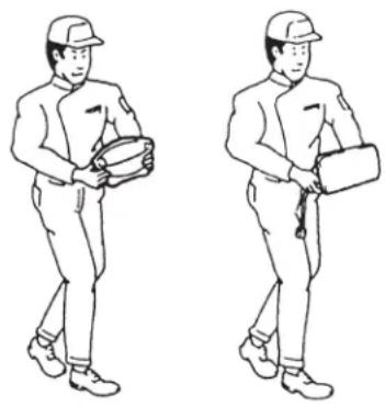
natural_image
Two identical line drawings of a person in uniform holding boxes, walking side by side (no text or symbols)ALWAYS PLACE AIR BAG (INFLATOR) MODULE ON WORKBENCH WITH TRIM COVER (AIR BAG OPENING) UP, AWAY FROM LOOSE OBJECTS.
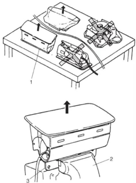
text_image
Technical diagram showing two views of a mechanical device with labeled components and directional arrows indicating assembly or movement.- Slit on workbench
- Workbench vise
- Lower mounting bracket
HANDLING AND SERVICING
WARNING:
- Many of service procedures require disconnection of "AIR BAG" fuse and air bag (inflator) modules (driver and passenger) from deployment loop to avoid an accidental deployment.
Driver and Passenger Air Bag (Inflator) Modules
- For handling and storage of a live air bag (inflator) module, select a place where the ambient temperature below 65^ (150^) , without high humidity and away from electric noise.
- When carrying a live air bag (inflator) module, make sure the bag opening is pointed away from you. In case of an accidental deployment, the bag will then deploy with minimal chance of injury. Never carry the air bag (inflator) module by the wires or connector on the underside of the module. When placing a live air bag (inflator) module on a bench or other surface, always face the bag up, away from the surface. As the live passenger air bag (inflator) module must be placed with its bag (trim cover) facing up, place it on the workbench with a slit or use the workbench vise to hold it securely at its lower mounting bracket. This is necessary so that a free space is provided to allow the air bag to expand in the unlikely event of accidental deployment. Otherwise, personal injury may result.
- Never dispose of live (undeployed) air bag (inflator) modules (driver and passenger). If disposal is necessary, be sure to deploy them according to deployment procedures described in Section 9J before disposal.
- The air bag (inflator) module immediately after deployment is very hot. Wait for at least half an hour to cool it off before proceeding the work.
- After an air bag (inflator) module has been deployed, the surface of the air bag may contain a powdery residue. This powder consists primarily of cornstarch (used to lubricate the bag as it inflates) and by-products of the chemical reaction. As with many service procedures, gloves and safety glasses should be worn.
SDM
- During service procedures, be very careful when handling a Sensing and Diagnostic Module (SDM). Never strike or jar the SDM. Never power up the air bag system when the SDM is not rigidly attached to the vehicle. All SDM and mounting bracket fasteners must be carefully torqued and the arrow must be pointing toward the front of the vehicle to ensure proper operation of the air bag system. The SDM could be activated when powered while not rigidly attached to the vehicle which could cause deployment and result in personal injury.
CAUTION:
- Even when the accident was light enough not to cause air bags to deploy, be sure to inspect system parts and other related parts according to instructions under “Repair and Inspection Required after an Accident” in Section 9J.
- When servicing parts other than air bag system, if shocks may be applied to air bag system component parts, remove those parts beforehand.
- When handling the air bag (inflator) modules (driver and passenger) or SDM, be careful not to drop it or apply an impact to it. If an excessive impact was applied (e.g., dropped from a height of 91.4 cm (3 feet) or more), never attempt disassembly or repair but replace it with a new one.
- When grease, cleaning agent, oil, water, etc. has got onto air bag (inflator) modules (driver and passenger), wipe off immediately with a dry cloth.
- Air bag wire harness can be identified easily as it is covered with a yellow protection tube. Be very careful when handling it.
- When an open in air bag wire harness, damaged wire harness, connector or terminal is found, replace wire harness, connectors and terminals as an assembly.
- Do not apply power to the air bag system unless all components are connected or a diagnostic chart requests it, as this will set a diagnostic trouble code.
- Never use air bag system component parts from another vehicle.
- When using electric welding, be sure to temporarily disable air bag system referring to “Disabling Air Bag System” under “Service Precaution” in Section 9J.
- Never expose air bag system component parts directly to hot air (drying or baking the vehicle after painting) or flames.
- WARNING/CAUTION labels are attached on each part of air bag system components. Be sure to follow the instructions.
- After vehicle is completely repaired, perform “Air Bag Diagnostic System Check” described in “Diagnosis” in Section 9J.
GENERAL PRECAUTIONS
The WARNING and CAUTION below describe some general precautions that you should observe when servicing a vehicle. These general precautions apply to many of the service procedures described in this manual, and they will not necessarily be repeated with each procedure to which they apply.
WARNING:
- Whenever raising a vehicle for service, be sure to follow the instructions under “VEHICLE LIFTING POINTS” on SECTION 0A.
- When it is necessary to do service work with the engine running, make sure that the parking brake is set fully and the transmission is in Neutral (for manual transmission vehicles) or Park (for automatic transmission vehicles). Keep hands, hair, clothing, tools, etc. away from the fan and belts when the engine is running.
- When it is necessary to run the engine indoors, make sure that the exhaust gas is forced outdoors.
- Do not perform service work in areas where combustible materials can come in contact with a hot exhaust system. When working with toxic or flammable materials (such as gasoline and refrigerant), make sure that the area you work in is well-ventilated.
- To avoid getting burned, keep away from hot metal parts such as the radiator, exhaust manifold, tailpipe, muffler, etc.
- New and used engine oil can be hazardous. Children and pets may be harmed by swallowing new or used oil. Keep new and used oil and used engine oil filters away from children and pets.
Continuous contact with used engine oil has been found to cause [skin] cancer in laboratory animals. Brief contact with used oil may irritate skin. To minimize your exposure to used engine oil, wear a long-sleeve shirt and moisture-proof gloves (such as dish washing gloves) when changing engine oil. If engine oil contacts your skin, wash thoroughly with soap and water. Launder any clothing or rags if wet with oil, recycle or properly dispose of used oil and filters. - Make sure the bonnet is fully closed and latched before driving. If it is not, it can fly up unexpectedly during driving, obstructing your view and resulting in an accident.
natural_image
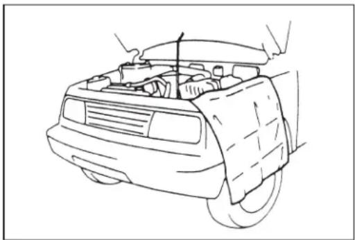
Line drawing of a car's front engine compartment showing wood, battery, and wheel (no text or symbols)CAUTION:
- Before staring any service work, cover fenders, seats and any other parts that are likely to get scratched or stained during servicing. Also, be aware that what you wear (e.g. buttons) may cause damage to the vehicle's finish.
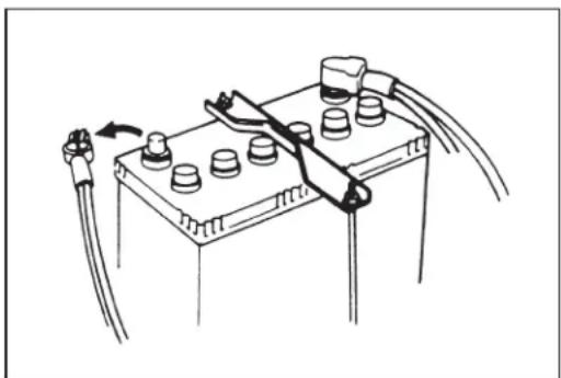
natural_image
Diagram of a battery pack with attached wires and connectors (no text or symbols)- When performing service to electrical parts that does not require use of battery power, disconnect the negative cable of the battery.
natural_image
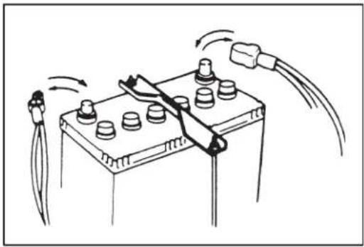
Diagram of a battery with attached plug and motor, showing wiring and components (no text or labels)- When removing the battery, be sure to disconnect the negative cable first and then the positive cable. When reconnecting the battery, connect the positive cable first and then the negative cable, and replace the terminal cover.

natural_image
Exploded view diagram of a mechanical assembly showing internal components (no text or labels)- When removing parts that are to be reused, be sure to keep them arranged in an orderly manner so that they may be reinstalled in the proper order and position.
natural_image
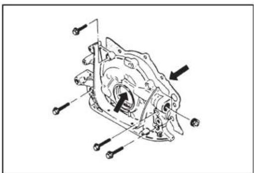
Mechanical assembly diagram showing a gear-like component with mounting holes and bolted joints (no text or labels)- Whenever you use oil seals, gaskets, packing, O-rings, locking washers, split pins, self-locking nuts, and certain other parts as specified, be sure to use new ones. Also, before installing new gaskets, packing, etc., be sure to remove any residual material from the mating surfaces.
text_image
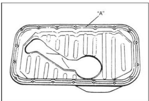
"A"- Make sure that all parts used in reassembly are perfectly clean.
- When use of a certain type of lubricant, bond or sealant is specified, be sure to use the specified type.
"A": Sealant 99000-31150

text_image
Technical diagram showing a mechanical assembly with labeled parts (A) and (B), including an inset view of a cylindrical component.- Be sure to use special tools when instructed.
Special Tool
(A): 09917-98221
(B): 09916-58210
natural_image
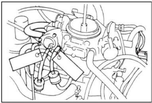
Technical line drawing of an engine cylinder assembly (no text or labels)- When disconnecting vacuum hoses, attach a tag describing the correct installation positions so that the hoses can be re-installed correctly.

natural_image
Technical line drawing of a mechanical assembly with pipes and valves (no text or symbols)●After servicing fuel, oil, coolant, vacuum, exhaust or brake systems, check all lines related to the system for leaks.
- For vehicles equipped with fuel injection systems, never disconnect the fuel line between the fuel pump and injector without first releasing the fuel pressure, or fuel can be sprayed out under pressure.
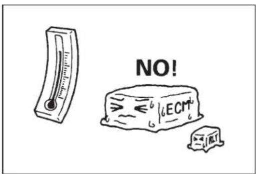
text_image
NO! ≤ ECm- When performing a work that produces a heat exceeding 80^ in the vicinity of the electrical parts, remove the heat sensitive electrical part(s) beforehand.

text_image
NO! ECM!- Use care not to expose connectors and electrical parts to water which will be a cause of a trouble.

text_image
NO! WILE SA●Always be careful not to handle electrical parts (computer, relay, etc.) in a rough manner or drop them.
PRECAUTIONS FOR CATALYTIC CONVERTER
For vehicles equipped with a catalytic converter, use only unleaded gasoline and be careful not to let a large amount of unburned gasoline enter the converter or it can be damaged.
- Conduct a spark jump test only when necessary, make it as short as possible, and do not open the throttle.
- Conduct engine compression checks within the shortest possible time.
- Avoid situations which can result in engine misfire (e.g. starting the engine when the fuel tank is nearly empty.).
text_image
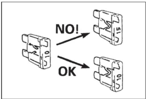
NO! OKPRECAUTIONS FOR ELECTRICAL CIRCUIT SERVICE
- When replacing a fuse, make sure to use a fuse of the specified capacity. Use of a fuse with a larger capacity will cause a damage to the electrical parts and a fire.

text_image
Diagram showing a device connected to a cable with an OFF ACC indicator, illustrating electrical or mechanical connection.- When disconnecting and connecting coupler, make sure to turn ignition switch OFF, or electronic parts may get damaged.

text_image
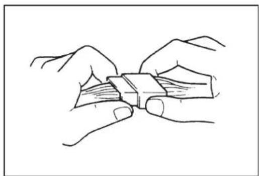
NO!- When disconnecting connectors, never pull the wiring harness. Unlock the connector lock first and then pull them apart by holding connectors themselves.
natural_image
Line drawing of two hands holding a small object, possibly a tool or device, with no visible text or symbols.- When connecting connectors, also hold connectors and put them together until they lock securely (a click is heard).
text_image
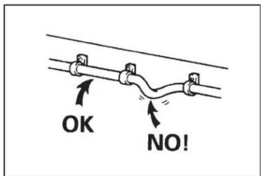
OK NO!- When installing the wiring harness, fix it with clamps so that no slack is left.

text_image
NO!- When installing vehicle parts, be careful so that the wiring harness is not interfered with or caught by any other part.
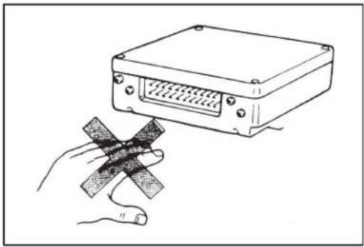
natural_image
Illustration of a device with a bandage being held by a hand (no text or symbols present)- Be careful not to touch the electrical terminals of parts which use microcomputers (e.g. electronic control unit like as ECM, PCM, P/S controller, etc.). The static electricity from your body can damage these parts.
- Never connect any tester (voltmeter, ohmmeter, or whatever) to electronic control unit when its coupler is disconnected. Attempt to do it may cause damage to it.
- Never connect an ohmmeter to electronic control unit with its coupler connected to it. Attempt to do it may cause damage to electronic control unit and sensors.
- Be sure to use a specified voltmeter/ohmmeter. Otherwise, accurate measurements may not be obtained or personal injury may result. If not specified, use a voltmeter with high-impedance (MΩ/V minimum) or a digital type voltmeter.
- When taking measurements at electrical connectors using a tester probe (2), be sure to insert the probe from the wire harness side (backside) of the connector (1).
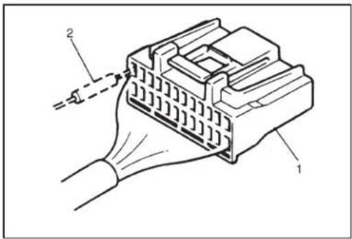
text_image
Technical diagram of an electrical connector with labeled parts 1 and 2, showing internal structure and cable connection.- When connecting meter probe (2) from terminal side of coupler (1) because it can't be connected from harness side, use extra care not to bend male terminal of coupler of force its female terminal open for connection.
In case of such coupler as shown connect probe as shown to avoid opening female terminal.
Never connect probe where (3) male terminal is supposed to fit.
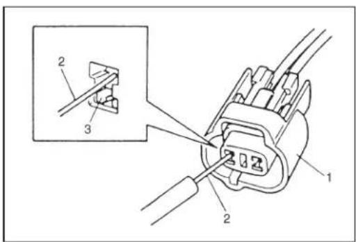
text_image
Technical diagram showing a connector assembly with labeled parts and an inset view of a mechanical component.- To avoid damage to the harness, protect its part which may contact against a part forming a sharp angle by winding tape or the like around it.
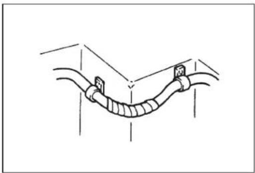
natural_image
Diagram of a U-shaped pipe with two connectors and vertical supports, no text or symbols present- When checking connection of terminals, check its male half for bend and female half for excessive opening and both for locking (looseness), corrosion, dust, etc.
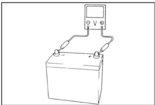
natural_image
Simple line drawing of a battery connected to a multimeter (no text or symbols)- Before measuring voltage to check for electrical system, check to make sure that battery voltage is 11 V or higher. Such terminal voltage check at low battery voltage will lead to erroneous diagnosis.
ELECTRICAL CIRCUIT INSPECTION PROCEDURE
While there are various electrical circuit inspection methods, described here is a general method to check its open and short circuit by using an ohmmeter and a voltmeter.
OPEN CIRCUIT CHECK
Possible causes for the open circuit are as follows. As the cause is in the connector or terminal in many cases, they need to be checked particularly carefully.
- Loose connection of connector.
●Poor contact of terminal (due to dirt, corrosion or rust on it, poor contact tension, entry of foreign object etc.).
●Wire harness being open.
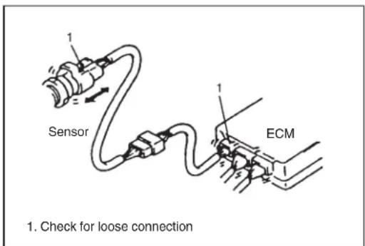
text_image
Sensor ECM 1. Check for loose connectionWhen checking system circuits including an electronic control unit such as ECM, TCM, ABS control module, etc., it is important to perform careful check, starting with items which are easier to check.
1) Disconnect negative cable from battery.
2) Check each connector at both ends of the circuit being checked for loose connection. Also check lock condition of connector if equipped with connector lock.

text_image
Check contact tension by inserting and removing just for once3) Using a test male terminal, check both terminals of the circuit being checked for contact tension of its female terminal. Check each terminal visually for poor contact (possibly caused by dirt, corrosion, rust, entry of foreign object, etc.). At the same time, check to make sure that each terminal is locked in the connector fully.

text_image
1. Looseness of crimping 2. Open 3. Thin wire (single strand of wire)4) Using continuity check or voltage check procedure described in the following page, check the wire harness for open circuit and poor connection with its terminals. Locate abnormality, if any.

text_image
A-1 C-1Continuity Check
1) Measure resistance between connector terminals at both ends of the circuit being checked (between A-1 and C-1 in the figure). If no continuity is indicated (infinity or over limit), that means that the circuit is open between terminals A-1 and C-1.
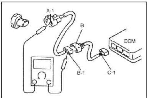
text_image
A-1 B B-1 C-1 ECM2) Disconnect the connector included in the circuit (connector-B in the figure) and measure resistance between terminals A-1 and B-1. If no continuity is indicated, that means that the circuit is open between terminals A-1 and B-1. If continuity is indicated, there is an open circuit between terminals B-1 and C-1 or an abnormality in connector-B.
Voltage Check
If voltage is supplied to the circuit being checked, voltage check can be used as circuit check.
1) With all connectors connected and voltage applied to the circuit being checked, measure voltage between each terminal and body ground.
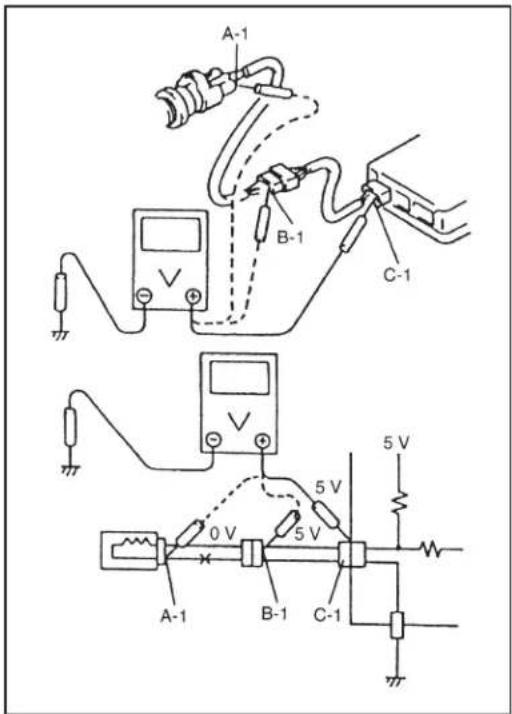
text_image
A-1 B-1 C-1 0 V 5 V 5 V A-1 B-1 C-1 5 VIf measurements were taken as shown in the figure at the left and results were as listed below, it means that the circuit is open between terminals B-1 and A-1.
Voltage Between:
C-1 and body ground: Approx. 5 V
B-1 and body ground: Approx. 5 V
A-1 and body ground: 0 V
Also, if measured values were as listed below, it means that there is a resistance (abnormality) of such level that corresponds to the voltage drop in the circuit between terminals A-1 and B-1.
Voltage Between:
C-1 and body ground: Approx. 5 V B-1 and body ground: Approx. 5 V —— 2 V voltage drop A-1 and body ground: Approx. 3 V

text_image
A-1 C-1 1 1 A-1 C-1 5 V 1. Other partsSHORT CIRCUIT CHECK (wire harness to ground)
1) Disconnect negative cable from battery. 2) Disconnect connectors at both ends of the circuit to be checked.
NOTE:
If the circuit to be checked is connected to other parts, disconnect all connectors of those parts. Otherwise, diagnosis will be misled.
3) Measure resistance between terminal at one end of circuit (A-1 terminal in figure) and body ground. If continuity is indicated, it means that there is a short to ground between terminals A-1 and C-1 of the circuit.
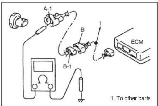
text_image
A-1 B B-1 1 ECM 1. To other parts4) Disconnect the connector included in circuit (connector B) and measure resistance between A-1 and body ground. If continuity is indicated, it means that the circuit is shorted to the ground between terminals A-1 and B-1.
INTERMITTENT AND POOR CONNECTION
Most intermittent are caused by faulty electrical connections or wiring, although a sticking relay or solenoid can occasionally be at fault. When checking it for proper connection, perform careful check of suspect circuits for:
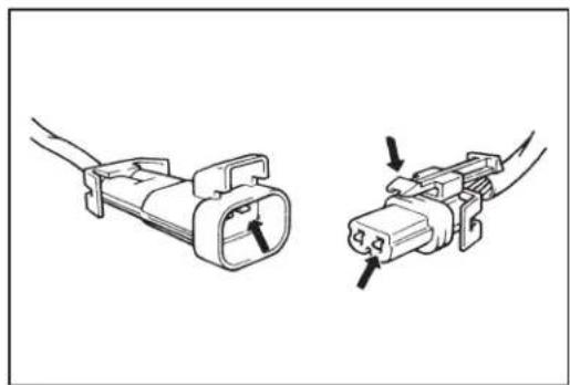
natural_image
Two types of electrical connectors shown in line drawings, one with a plug and cable, the other with a socket (no text or symbols)●Poor mating of connector halves, or terminals not fully seated in the connector body (backed out).
- Dirt or corrosion on the terminals. The terminals must be clean and free of any foreign material which could impede proper terminal contact. However, cleaning the terminal with a sand paper or the like is prohibited.
●Damaged connector body, exposing the terminals to moisture and dirt, as well as not maintaining proper terminal orientation with the component or mating connector.

text_image
1. Check contact tension by inserting and removing just once 2. Check each terminal for bend and proper alignment- Improperly formed or damaged terminals.
Check each connector terminal in problem circuits carefully to ensure good contact tension by using the corresponding mating terminal.
If contact tension is not enough, reform it to increase contact tension or replace.

natural_image
Line drawing of hands connecting a cable to a connector (no text or symbols)●Poor terminal-to-wire connection.
Check each wire harness in problem circuits for poor connection by shaking it by hand lightly. If any abnormal condition is found, repair or replace.
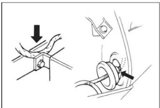
natural_image
Technical illustration showing two mechanical assembly steps: one with a downward arrow and the other with a curved component inserted into a pipe (no text or symbols)●Wire insulation which is rubbed through, causing an intermittent short as the bare area touches other wiring or parts of the vehicle.
●Wiring broken inside the insulation. This condition could cause continuity check to show a good circuit, but if only 1 or 2 strands of a multi-strand-type wire are intact, resistance could be far too high.
If any abnormality is found, repair or replace.
PRECAUTION FOR INSTALLING MOBILE COMMUNICATION EQUIPMENT
When installing mobile communication equipment such as CB (Citizens-Band)-radio or cellular-telephone, be sure to observe the following precautions.
Failure to follow cautions may adversely affect electronic control system.
- Keep the antenna as far away as possible from the vehicle's electronic control unit.
- Keep the antenna feeder more than 20 cm (7.9 in.) away from electronic control unit and its wire harnesses.
- Do not run the antenna feeder parallel with other wire harnesses.
- Confirm that the antenna and feeder are correctly adjusted.
PRECAUTION IN SERVICING FULL-TIME 4WD VEHICLE
When performing any of the following types of work, be sure to make the vehicle as front wheel drive by cutting transmission of driving force to the rear wheels. Otherwise, rear wheels are driven and vehicle accidents, damage and personal injury may result.

text_image
Testing following items • Speedometer • Chassis dynamo • Brake • Wheel balance (on car type) Towing vehicle with front or rear wheels lifted up Driving front wheels which are jacked up
text_image
4WD 1, (a) 2WD 1, (a) 1. Transfer lock bolt 2. Shift fork shaftSWITCHING FROM 4WD TO 2WD
Set 4WD/2WD select lever located at lower side of transfer driven case to 2WD as follows.
1) Loosen transfer lock bolt.
2) Push in shift fork shaft fully.
3) With shift fork shaft pushed in, tighten transfer lock bolt.
Tightening Torque
(a): 19 N·m (1.9 kg-m, 14.0 lb-ft)
NOTE:
- If shift fork shaft is hard to move, try to move it while turning it to the right and left little by little. Do the same when setting back to 4WD after servicing vehicle.
- Upon completion of servicing, always set shift fork shaft back to 4WD.
natural_image
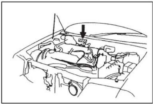
Line drawing of a car engine bay with visible internal components and a downward arrow indicating a component (no text or symbols)IDENTIFICATION INFORMATION VEHICLE IDENTIFICATION NUMBER
The number is punched on the front dash panel in the engine room.
text_image
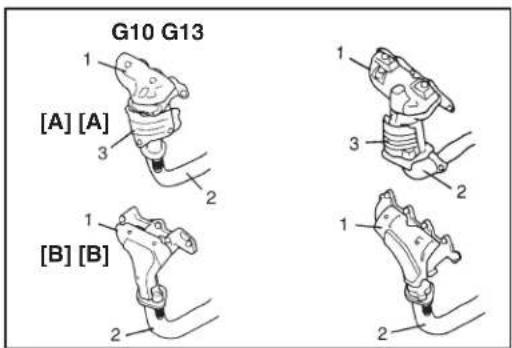
G10 G13 1 [A] [A] 3 2 1 [B] [B] 2 1 3 2 1 2IDENTIFICATION WHETHER VEHICLE EQUIPPED WITH WU-TWC OR NOT
It can be identified by the shape of exhaust manifold (1) and exhaust pipe (2).
[A]: Vehicle equipped with WU-TWC (3)
[B]: Vehicle not equipped with WU-TWC
natural_image
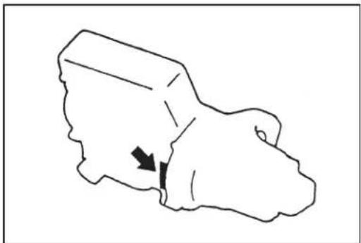
Simple line drawing of a 3D object with an arrow pointing to a small feature (no text or symbols)ENGINE IDENTIFICATION NUMBER
The number is punched on the cylinder block.
text_image
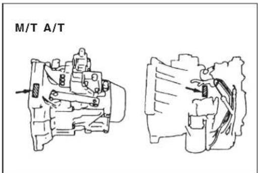
M/T A/TTRANSMISSION IDENTIFICATION NUMBER
The number is punched on the transmission case.
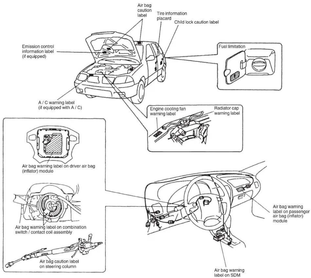
WARNING, CAUTION AND INFORMATION LABELS
The figure below shows main labels among others that are attached to vehicle component parts. When servicing and handling parts, refer to WARNING/CAUTION instructions printed on labels. If any WARNING/CAUTION label is found stained or damaged, clean or replace it as necessary.
NOTE: Air bag CAUTION /WARNING labels are attached on the vehicle equipped with air bag system only.
text_image
Air bag caution label Tire information placard Child lock caution label Fuel limitation Emission control information label (if equipped) A / C warning label (if equipped with A / C) Engine cooling fan warning label Radiator cap warning label Air bag warning label on driver air bag (inflator) module Air bag warning label on combination switch / contact coil assembly Air bag caution label on steering column Air bag warning label on passenger air bag (inflator) module Air bag warning label on SDMVEHICLE LIFTING POINTS
WARNING:
- Before applying hoist to underbody, always take vehicle balance throughout service into consideration. Vehicle balance on hoist may change depending of what part to be removed.
- Before lifting up the vehicle, check to be sure that end of hoist arm is not in contact with brake pipe, fuel pipe, bracket or any other part.
- When using frame contact hoist, apply hoist as shown (right and left at the same position). Lift up the vehicle till 4 tires are a little off the ground and make sure that the vehicle will not fall off by trying to move vehicle body in both ways. Work can be started only after this confirmation.
- Make absolutely sure to lock hoist after vehicle is hoisted up.
When using frame contact hoist:
Front Support Location Rear Support Location
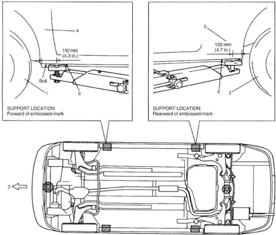
text_image
4 110 mm (4.3 in.) Bolt 6 5 120 mm (4.7 in.) 6 2 SUPPORT LOCATION Forward of embossed-mark SUPPORT LOCATION Rearward of embossed-mark 3- Front left tire
- Rear left tire
- Front
- Front fender left panel
- Rear left panel
- Embossed-mark
: Support position for frame contact hoist and safety stand
: Floor jack position