VAZ-21214-20 (1999) - Car LADA - Free user manual and instructions
Find the device manual for free VAZ-21214-20 (1999) LADA in PDF.

User questions about VAZ-21214-20 (1999) LADA
0 question about this device. Answer the ones you know or ask your own.
Ask a new question about this device
Download the instructions for your Car in PDF format for free! Find your manual VAZ-21214-20 (1999) - LADA and take your electronic device back in hand. On this page are published all the documents necessary for the use of your device. VAZ-21214-20 (1999) by LADA.
USER MANUAL VAZ-21214-20 (1999) LADA
natural_image
Cutaway illustration of a car showing internal engine and suspension components (no text or symbols)VAZ-21213, VAZ-21214, VAZ-21214-20, VAZ-21215
REPAIR MANUAL
Contents
Section 1. General data....4
Section 2. Engine ......7
Engine - removal and refitting....12
Cylinder block ....19 Inspection and repair....19
Pistons and connecting rods 21
Selecting piston to cylinder 23
Dismantling and reassembly....23
Crankshaft and flywheel 24
Design description....24
Inspection and overhaul....24
Cylinder head and valve gear....26
General description ......26
Valve clearance adjustment 27
Cylinder head - removal and refitting....28
Cylinder head - dismantling and reassembly......28
Camshaft and timing gear 32
Cooling system 34
Lubrication system....38
Fuel system 42
Carburettor....46
Exhaust gas recirculation system....55
Exhaust system 46
Chapter 3. Power train....57
Clutch 57
Gearbox....64
Transfer box 73
Drive line 80
Rear axle....84
Front axle 96
Chapter 4. Wheel suspensions ....100
Front suspension....102
Rear suspension....110
Chapter 5. Steering ......115
Steering - inspection, check and adjustment .....116
Steering mechanism....118
Chapter 6 Braking system....121
Front brakes 128
Rear brakes....130
Handbrake....134
Chapter 7. Electrical system....135
Wiring and fuses ....135
Battery....136
Alternator....140
Starter motor 146
Ignition system 149
Lighting and signalling....156
Windscreen wiper/washer 159
Instruments....163
Chapter 8. Bodywork....167
Bodywork - repair 169
Paintwork....172
Door....176
Bonnet, bumpers....179
Bodywork glazing and windscreen washers .....180
Instrument panel, seats....181
Heater unit....183
Chapter 9. VAZ-21213 vehicle modifications, alternative and additional equipment....185
VAZ-21214 vehicle 185
Engine repair - description ....185
Central Injection Unit....186
VAZ-21214-20 vehicle....189
Engine 21214-10....190
VAZ-21215-10 vehicle....197
Cooling system....200
Lubrication system 202
Fuel system....202
Exhaust emission system....203
Electrical system 203
Steering with BREED «SRS-40»
driver's airbag in the steering wheel 209
Attachments....212
This Manual provides information on routine maintenance and servicing and is intended for engineers and mechanics of service outlets, garages and workshops.
The Manual covers the following models:
VAZ-21213 model - an off-road vehicle, three-door body of all-steel unitary construction, with 1.7 litre carburettor engine;
VAZ-21214 model - with 1.7 litre Central Fuel Injection Engine;
VAZ-21214-20 model - with 1.7 litre Sequential Fuel Injection Engine;
VAZ-21215 model - with Turbo Diesel Engine.
The chapters of the manual give full descriptions of VAZ-21213 vehicle units. For general description, service and repair procedures applicable to other models, refer to Section 9 where you can also find the information on additional and alternative equipment fitted to the vehicles.
The Manual provides a detailed description of service operations on the base of OEM parts, with helpful information on fault diagnosis, along with clear indications on removal and refitting, dismantling and reassembly, adjustment and repair of various vehicle units.
We recommend to use special tools and working facilities as listed in Attachment No 2. Tighten the thread connections to torques specified in Attachment No 1. Basic adjustments and inspection checks are outlined in Attachment No 3. Refer to Attachment 4 for recommended lubricants and fuels.
Due to the on-going process of vehicle improvement aimed to enhance the VAZ vehicle reliability and performance, the manufacturer can make alterations and design changes which may fail to enter this publication. Such changes and alterations will be incorporated into our manuals at the earliest opportunity.
The Manual describes the vehicle design as of October 1999.
Section 1. General Data
Table 1-1
TECHNICAL SPECIFICATION
| Features VAZ-21213 VAZ-21214 VAZ-21214-20 VAZ-21215 |
General
| Number of seats 5 5 5 5 | ||||
| Kerb weight, kg 1210 1210 1210 1240 | ||||
| Payload, kg 400 400 400 | 400 | |||
| Overall dimensions | Fig.1-1 | |||
| Maximum braking distance at GVW and 80 km/hon horizontal dry flat asphalt road, not greater, meters: | ||||
| • with service braking system applied | 40 | 40 | 40 | 40 |
| • with emergency system applied (either of two service braking circuits) | 90 | 90 | 90 | 90 |
| Maximum speed* in top gear, km/h: | ||||
| • with driver and passenger | 137 137 137 | 130 | ||
| • at full load | 135 135 135 | 128 | ||
| Acceleration time*, 0 to 100 km/h through gear shifting, seconds: | ||||
| • with driver and passenger | 19 | 19 | 19 | 22 |
| • at full load | 21 | 21 | 21 | 24 |
Engine
| Model | 21213 | 21214 | 21214-10 | DHW (XUD-9SD) |
| Type | Four-stroke,petrol, carburettor | Four-stroke,petrol, CFI | Four-stroke,petrol, sequential injection | Four-stroke,turbo diesel |
| No of cylinders | four in-line | four in-line | four in-line | four in-line |
| Bore x stroke, mm | 82x80 | 82x80 | 82x80 | 83x88 |
| Capacity, litre | 1.69 | 1.69 | 1.69 1.905 | |
| Compression ratio | 9.3:1 9.3:1 9.3:1 | 21.5:1 | ||
| Maximum power:as per GOST 14846 (net), at least, kW (h.p.) | 58 (78.9) | 58 (78.9) | 58.5 (79.6) | 55 (74.8) |
| as per ISO 1585, kW | 58 | 58 | 58.5 | 55 |
| Maximum crankshaft speed at maximum power, rpm 5200 5400 5000 4600 | ||||
| Firing order | 1-3-4-2 | 1-3-4-2 | 1-3-4-2 | 1-3-4-2 |
Power train
Clutch single dry plate, diaphragm spring
Clutch release mechanism hydraulic, servo spring
Transmission 5-speed, synchro units on all forward gears
Gear ratio:
- first gear 3.67 3.67 3.67 3.67
• second gear 2.10 2.10 2.10 2.10
• third gear 1.36 1.36 1.36 1.36
• fourth gear 1.00 1.00 1.00 1.00 - fifth gear 0.82 0.82 0.82 0.82
• reverse gear 3.53 3.53 3.53 3.53
Transfer case two-gear, lockup differential
Gear ratio:
• top gear 1.2 1.2 1.2 1.2
- bottom gear 2.135 2.135 2.135 2.135
Transfer case differential
bevel gears, two pinion gears
Drive line:
• from transmission to transfer case
• from transfer case to front and rear axles
• from front axle to wheels
flexible coupling and CV joints
two universal joints on needle bearings with grease nipples and yokes open, with CV joints
Final drive ratio, front and rear axles
bevel, hypoid
- gear ratio 3.9 3.9 3.9 3.9
• differential bevel, two pinion gears
Suspension and wheels
Front suspension
independent, lower track control arms (wishbones), coil springs, hydraulic telescopic shock-absorbers, anti-roll bar
Rear suspension
rigid axle beam with Panhard rod and four trailing arms, coil springs/hydraulic telescopic shock-absorbers
Wheels
- wheel rim 127J x 406 (5J x 16)
Tyres
tubed, cross-ply or radial ply
size:
• cross-ply tyres 175 x 406 (6.95 x16),
- radial-ply tyres 175/80R16
Steering
Steering mechanism globoidal worm, double-crest roller, steering ratio 16.4
Steering linkage three links, relay rod and two steering rods,
drop arm, idler arm and swing arms
Braking system
Service braking system:
- front brakes disc-type, floating caliper, automatic disc-to-pad clearance adjustment
- rear brakes drum-type, self-applying shoes and automatic shoe-to-drum clearance adjustment
- brake operation line
foot-type, hydraulic, dual circuit, split diagonally, vacuum servo unit and pressure regulator
Handbrake cable-operated on rear wheels
Electrical system
Wiring diagram single-wire, negative earth type
Voltage, volts 12
Battery 6CT-55A, 55 ampere-hour
Alternator AC, integral diode plate and electronic voltage regulator
Starter motor pre-engaged, solenoid switch and overrun clutch
Body
Type
all-steel unitary construction, monocoque, three-door, double-space

text_image
705 2200 3740 835 1640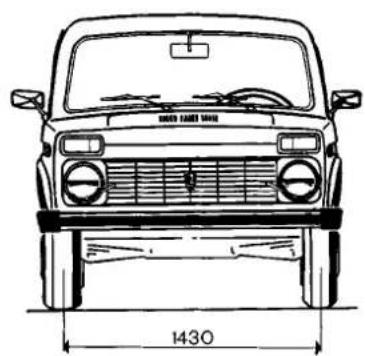
natural_image
Front view line drawing of a car with grille and side-mounted roof (no text or symbols)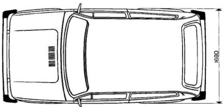
natural_image
Top-down line drawing of a car showing front and rear views with dimension标注 (no text or symbols)
text_image
1814 1400Fig.1-1. Basic overall dimensions of VAZ-21213 vehicle
Section 2. Engine
Refer to Fig.2-1 and Fig.2-2 for front and side sectional views of the engine.

natural_image
Cross-sectional technical drawing of an internal combustion engine cylinder (no text or labels)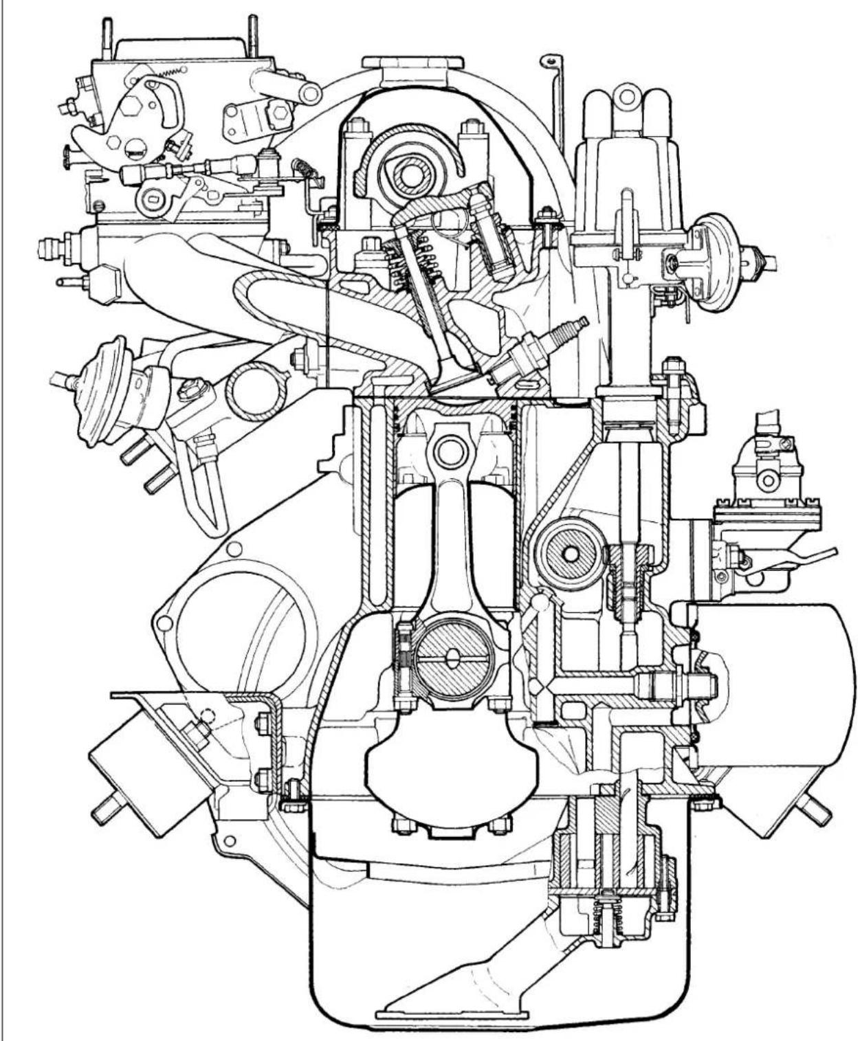
natural_image
Technical line drawing of a mechanical assembly (no text or labels visible)Fig.2-2. Front sectional view of the engine
Fault diagnosis
Symptom/fault Remedy
Engine fails to start
- No fuel to carburettor:
- blocked fuel pipes or fuel filter;
- clogged carburettor or fuel pump filters;
- faulty fuel pump
- Ignition system fault
- Carburettor fuel cutoff solenoid fails to open at ignition switch-on:
- disconnected, loose or broken wiring to solenoid or solenoid control unit;
- faulty solenoid control unit;
- defective fuel cutoff solenoid
-
Carburettor choke not opening at first flashes in cylinders
-
Carry out the following operations:
- blow fuel pipes, clean fuel tank, renew fuel filter;
- clean filters;
- check pump operation and renew any damaged components
- Refer to section «Ignition system»
- Carry out the following:
- check wiring and connections, renew damaged wires;
- renew control unit;
- replace solenoid with a new one
- Eliminate any leakage of choke pull-down unit
Engine idles erratically or stalls
- Incorrectly adjusted idle speed
- Defective carburettor solenoid control system
- Faulty carburettor:
- blocked carburettor jets or internal passages;
- water in carburettor;
- broken choke control diaphragm
- Ignition system fault
- Vacuum leak through damaged hose between intake pipe and brake servo unit
- Air leak through gaskets at connections between intake pipe and carburettor/cylinder head
-
Leaking distributor vacuum pipe
-
Adjust idle speed
- Refer to «Engine fails to start»
- Carry out the following:
- blow carburettor jets and internal passages;
- remove water from carburettor, drain sludge from fuel tank;
- fit new diagram
- Refer to section «Ignition system»
- Replace damaged hose
- Tighten retaining nuts or renew gaskets; eliminate carburettor flange deformation or fit new carburettor
- Fit new pipe in place of damaged one
Engine lacks power and has poor acceleration
- Partly open throttle
- Choked air cleaner element
- Ignition system fault
- Faulty fuel pump
- Faulty carburettor:
- faulty accelerator pump;
- blocked main jets;
- partly open choke;
- low fuel level in float chamber;
- leaky throttle enrichment diaphragm
- Restricted fuel tank vent pipe
- Incorrect valve clearances
- Misaligned timing marks
- Insufficient cylinder compression - below 1 MPa (10 kgf/cm ^2 ):
- broken or sticking piston rings;
- poor valve-to-seat fitting;
-
excessively worn cylinders or piston rings
-
Adjust throttle linkage
- Change filter element
- Refer to section «Ignition system»
- Check pump operation and renew any damaged components
- Carry out the following:
- check pump operation, renew damaged parts;
- blow jets with compressed air;
- adjust choke operation;
- adjust float;
- replace diaphragm
- Blow pipe with compressed air
- Adjust valve clearances
- Adjust timing belt accordingly, align timing marks
- Carry out the following:
- clean piston rings or grooves from carbon deposits, renew damaged components;
- replace damaged valves, regrind valve seats;
- replace pistons, rebore and hone cylinders.
Main bearing knocking
Typical knocking or thumping noticeable at sudden throttle opening at idle which intensifies with higher crankshaft rate. Excessive endfloat of crankshaft causes sharper irregular knocking, especially noticeable during smooth increase or decrease in crankshaft speed.
- Early ignition
- Insufficient pressure oil
- Loose flywheel securing bolts
- Excessive main bearing running clearance
-
Excessive thrust washers-to-crankshaft clearance
-
Adjust ignition timing
- Refer to subsection «Insufficient oil pressure at idle»
- Tighten bolts to torque specified
- Grind journals and renew bearing shells
- Fit new thrust washers, check clearance
Big-end bearing knocking
Big-end bearing knocking is sharper than that of main bearings. It is noticeable during engine idle at sudden throttle opening. The origin of knocking can be easily identified through switching off spark plugs one at a time.
- Insufficient oil pressure
-
Excessive big-end bearing running clearance
-
Refer to «Insufficient oil pressure at idle»
- Fit new bearing shells and regrind journals
Piston slap
Thumping noise caused by piston «runout» in cylinder. Most noticeable at low crankshaft speed and under load.
- Excessive piston-to-cylinder bore clearance
-
Excessive gudgeon pin-to-piston groove clearance
-
Renew pistons, rebore and hone cylinders
- Fit new rings or new pistons with rings
Knocking of intake or exhaust valves
Excessive valve clearances cause typical regular noise; its frequency is lower than the frequency of any other engine noise, since the valves are operated by camshaft rotating at half the crankshaft speed.
- Excessive valve clearances
- Broken valve spring
- Excessive valve-to-guide clearance
- Worn camshaft lobes
-
Loose locknut of adjuster bolt
-
Adjust clearances
- Renew spring
- Replace worn parts
- Renew camshaft and levers
- Adjust clearance between lever and cam, tighten locknut
Excessive noise of camshaft operation line
Noise from camshaft operation line is caused by clearances between engagement elements and becomes noticeable in general engine noise at low crankshaft speed.
- Loose chain caused by general wear
- Broken chain tensioner shoe or damper
-
Seized chain tensioner plunger rod
-
Tighten chain
- Renew tensioner shoe or damper
- Eliminate seizure
Insufficient oil pressure at warm engine idle
- Foreign particles entrapped under oil pump relief valve
- Seized oil pressure relief valve
- Worn oil pump gears
- Excessive main bearing running clearance
- Excessive camshaft bearing journal-to-bearing housing clearance
-
Incorrect oil grade or inappropriate oil quality
-
Clean valve from foreign particles and flash, clean oil pump
- Renew valve
- Repair oil pump
- Turn journals and renew bearing shells
- Renew camshaft or bearing housing
- Change oil as recommended in Attachment 4
Excessive oil pressure on warm engine
- Seized oil pressure relief valve
-
Excessively tough spring of oil pressure relief valve
-
Renew valve
- Renew spring
Excessive oil consumption
- Oil leaking through engine gaskets
- Restricted crankcase ventilation system
- Worn piston rings
- Broken piston rings
- Foul windows of oil scraper rings or foul slots in piston grooves due to wrong oil
- Worn or damaged valve oil caps
-
Badly worn valve stems or guides
-
Tighten fittings or replace gaskets and oil seals
- Wash components of crankcase ventilation system
- Rebore and renew pistons and rings
- Renew rings
- Clean windows and slots of carbon, change motor oil as recommended in Attachment 4
- Renew oil caps
- Renew valves, repair cylinder head
Excessive fuel consumption
- Choke not fully opened
- Excessive resistance to vehicle motion
- Incorrect ignition timing
- Defective distributor vacuum unit
- High fuel level in carburettor:
- leaking needle valve or its gasket;
- seizure or excessive friction hindering normal float operation
- Choked carburettor air jets
- Leaking part throttle enrichment diaphragm
- Carburettor solenoid failed to shut off fuel at overrun:
- no earthing of idle switch sliding contact;
- broken wire between control module and carburettor idle switch;
-
faulty control module
-
Adjust choke linkage
- Check and adjust pressures in tyres, braking system, wheel alignment
- Adjust ignition timing
- Renew vacuum unit or ignition distributor
- Carry out the following:
- check for any foreign matter entrapped between needle and valve seat; renew valve or gasket as applicable;
- check and when necessary replace floats
- Clean jets
- Replace diaphragm
- Following to be done:
- clean solenoid contact surfaces;
- check wiring and connections, renew damaged wire;
- renew control unit
Engine overheating
Coolant temperature gauge needle is in the red sector. Start tracing the failure with checking coolant temperature gauge and its sender (Refer to section «Instrumentation»).
- Slackened pump and alternator drive belt
- Insufficient coolant in system
- Incorrect ignition timing
- Dirty radiator outside
- Defective thermostat
- Faulty radiator cap inlet valve (opening pressure is below 0.07 MPa (0.7 kgf/cm ^2 )
-
Defective coolant pump
-
Adjust drive belt tension
- Top up coolant to cooling system
- Adjust ignition timing
- Clean radiator outside with water jet
- Renew thermostat
- Renew cap
- Check pump operation, renew or repair pump
Sudden coolant drop in expansion tank
- Damaged radiator
- Damaged cooling hoses or pipe gaskets, loose clips
- Leaking heater tap or heater matrix
- Leaking water pump seal
- Damaged radiator cap or cap seal
- Defective cylinder head gasket
- Leaks from fissures in cylinder block or cylinder head
-
Leaks from fissures in water pump housing, water jacket return pipe, thermostat, expansion tank or intake pipe
-
Repair or renew radiator
- Renew damaged hoses or gaskets, tighten hose clips
- Renew tap or heater matrix
- Renew seal
- Renew cap
- Renew gasket
- Check cylinder block and cylinder head for leakage; renew damaged components in case of evident cracking
- Check for leaks; renew components in case of fissures; minor leaks can be cured by adding a radiator sealant such as НИИСС-1
Engine - removal and refitting
Put the vehicle on a lift or over an inspection pit and apply the handbrake. Take out the spare wheel and its supporting pipe. Disconnect the battery leads and withdraw the battery. Unbolt and remove the bonnet.
To remove the air cleaner, disconnect its hoses, remove the cover and filter element. Temporarily plug the carburettor.
Disconnect the throttle linkage and choke cable.
Disconnect the wires from the fuel cutoff solenoid, idle switch, oil pressure sensor, coolant temperature sensor, ignition distributor, alternator and starter motor.
Drain coolant from the radiator, cylinder head and heater unit. To do this, shift the heater tap control lever to the right, undo the caps on the cylinder block left side and radiator right-hand fluid cooler, screw instead the return hoses connectors, then undo the caps of the expansion tank and radiator.
Separate the fan cowl halves and remove the fan blower cowl. Disconnect the coolant supply and return hoses from the engine. Undo two bolts retaining the radiator to the body, release the top catch of the fan cowl, move the top radiator toward the engine and withdraw the radiator from the engine bay complete with the thermostat and associated hoses. Remove the fan cowl. Undo the nuts holding the downpipe to exhaust manifold. Detach the downpipe from the bracket on the transmission and lower it down.
Slacken the clips, disconnect the hoses from the fuel pump and secure the pump in the position that excludes any fuel leakage. Detach the fuel return hose from the carburettor.
Release the clips and disconnect the hoses from the heater manifolds, detach the brake servo hose from the intake pipe.
Use socket spanner 02.7812.9500 to unbolt the starter motor from the clutch housing. Undo the bolts holding the clutch housing cover to the lower clutch. Using A.55035 undo the clutch bell-housing to the cylinder block.
Hoist the beam TCO-3/379 and secure the engine right side to the lifting yoke at the front exhaust manifold stud, while the left side shall be secured through the clutch housing mounting hole.
Slightly tension the hoist, undo the nuts that retain front engine mounting rubbers 3 (Fig.2-3) to the side brackets, undo the nut and bolt holding the front axle housing to the engine brackets. Disconnect the engine negative lead.
Lift out the engine, first raise its top in order to take the bolts of the mounting rubber out of the bracket holes, then move the engine forward in order to release the input shaft from the bearing in the crankshaft flange.

text_image
Technical diagram of an engine assembly with numbered parts and exploded view, likely for maintenance or repair.Fig. 2-3. Engine mounting unit:
1 - right-hand support bracket with rubber; 2 - left-hand support bracket; 3 - mounting rubber; 4 - cross-piece, rear mounting; 5 - bracket with rear mounting

text_image
Fig.2-4. Removing the oil filter using tool A.60312Remove the starter motor heat shield, followed by the starter motor, hot air intake complete with the supply hose. Remove from the cylinder head two side brackets together with the front engine mounting rubbers.
Unbolt the clutch and withdraw it.
Refitting is a reversal of the removal procedure. Draw special attention to the engine-to-transmission connection: the input shaft must precisely engage the clutch disc splines. Furthermore, for perfect engine/transfer box centering, the centering washers of the front engine mounting rubbers must be in the respective side brackets holes.
Engine - dismantling
Flush the engine, mount it on a stand for dismantling and drain the oil sump.
Remove the carburettor, for that disconnect the hoses and throttle operating rod.
Remove the fuel pump and ignition distributor. Use spanner 67.7812.9514 to unscrew the spark plugs and coolant temperature sensor.
Remove the alternator and water pump drivebelt. Remove the alternator and its retaining bracket.
On the pump and exhaust manifold disconnect the coolant supply pipe from the heater.
From the pump and exhaust manifold disconnect the coolant supply pipe from the heater.
Use tool A.60312 to undo the oil filter with seal, remove the oil filter and seal (Fig.2-4).
Unscrew the oil pressure warning lamp sender. Remove the crankcase vent breather cover, crankcase and oil pump. Remove the oil separator drain pipe catch and take out the oil separator.
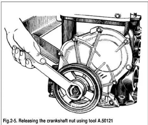
To remove the crankshaft pulley, secure the flywheel using A.60330/R (Fig. 2-10) and undo the nut using tool A.5012 (Fig. 2-5). Withdraw the valve cover and timing cover. Unbolt the
text_image
Fig.2-5. Releasing the crankshaft nut using tool A.50121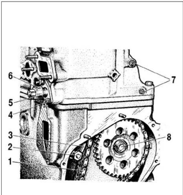
text_image
Technical diagram of a mechanical assembly with numbered parts labeled 1 through 8Fig.2-6. Removing the chain tensioner and damper:
1 - camshaft timing chain; 2 - shoe retaining bolt; 3 - tensioner chain; 4 - tensioner retainer nut; 5 - tensioner housing; 6 - tensioner cap nut; 7 - chain damper securing bolts; 8 - oil pump shaft sprocket retaining bolt
camshaft and oil pump drive shaft sprockets.
Slacken chain tensioner cap nut 6 (Fig.2-6), undo nut 4 holding it to the cylinder head, remove the tensioner; then unbolt and remove chain tensioner shoe 3.
Undo the chain stop pin, remove the oil pump and camshaft sprockets, then take off the chain.
Loosen studs 4 nuts (Fig. 2-7). Remove the camshaft bearing housing. Undo studs 4 nuts, remove thrust flange 1 and withdraw the camshaft exercising maximum care not to damage the camshaft bearing housing surface.
Unbolt the cylinder head and withdraw it complete with the exhaust manifold and intake pipe.
text_image
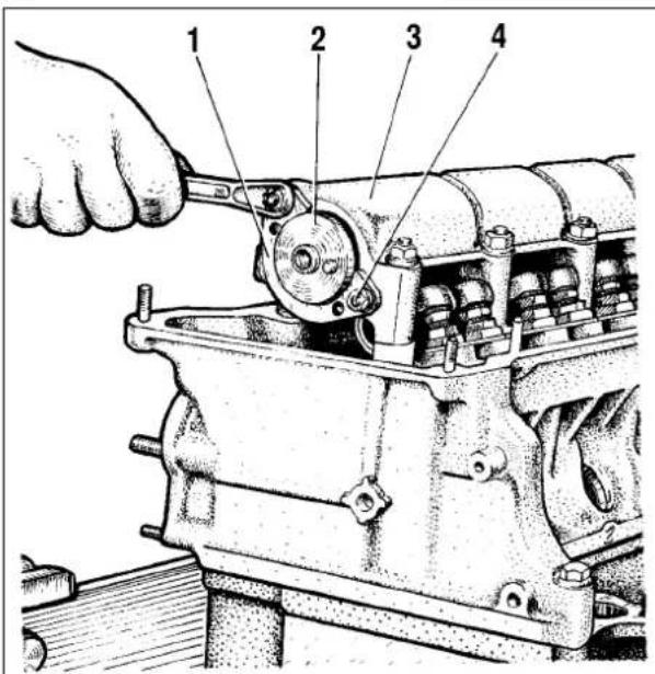
Technical diagram of a mechanical assembly with numbered parts labeled 1 to 4Fig.2-7. Removing the camshaft thrust flange:
1 - thrust flange; 2 - camshaft; 3 - bearing housing; 4 - thrust flange securing stud
Remove thrust flange 1 (Fig.2-8) of the oil pump drive shaft and take the shaft out of the cylinder block.
Using picker A.40005/1/7 (kit A.40005) drive the sprocket off the crankshaft (Fig.2-9).
Undo the connecting rod bolts, remove the big end cap and carefully lift the pistons with the conrods through the cylinders. Mark the piston, connecting rod, main and big-end bearing shells for position to facilitate the reassembly.
WARNING. When removing the pistons and conrods, do not press out the connecting rod bolts.
Fit tool 5 (Fig.2-10), undo bolts 3, remove washer 4 and the flywheel from the crankshaft. Remove the front clutch housing cover.
Using tool A.40006, take the input shaft bearing out from the crankshaft (Fig.2-11).
Remove the crankshaft oil seal retainer.
Unbolt the main bearing cap bolts, remove them complete with the lower bearing shells, then lift out the crankshaft, top bearing shells and rear bearing thrust washers.
Engine - reassembly
Follow the engine reassembly procedure as below:
Locate a clean cylinder block and screw in any missing dowels. Oil the crankshaft bearing shells, thrust washers, pistons and oil seals. Always fit new crankshaft oil seals when reassembling the engine after overhaul.
text_image
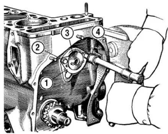
Technical diagram of an engine cylinder assembly with numbered parts for identificationFig.2-8. Removing the oil pump shaft:
1 - thrust flange; 2 - flange securing bolt; 3 - oil pump shaft; 4 - wrench
natural_image
Technical line drawing of an engine cylinder assembly (no text or labels)Fig. 2-9. Removing the crankshaft sprocket using a picker

text_image
Technical diagram showing a mechanical assembly with numbered components for identificationFig.2-10. Removing the flywheel:
1 - wrench; 2 - flywheel; 3 - flywheel securing bolt; 4 - washer; 5 - tool A.60330/R to lock the flywheel stationary; 6 - front clutch housing cover

natural_image
Illustration of hands operating a mechanical component with a tool, no visible text or symbols in the diagram itself.Fit the centre main bearing shells without an oilway into the bearing recesses. Fit into other cylinder bores the bearing shells with an oilway, while into the relevant main bearing caps - the bearing shells without an oilway. Lower the crankshaft into position, then stick two thrust washers into the rear bearing recesses (Fig.2-12).
WARNING. The washers must be fitted so that their oil-ways face away from the bearings in the block and cap (antifriction coat is applied on the washer surface). At the rear of the rear main bearing there fitted a sintered thrust washer (yellow), while at the front - a steel-aluminium thrust washer.
Locate the main bearing caps according to the marks on their outer surface (Fig.2-13). Tighten the cap securing bolts.
Check the crankshaft endfloat. To do this, turn the cylinder block to have the rear side up and position the dial gauge foot against the crankshaft flange (Refer to Fig.2-14). Moving the crankshaft up and down (using screwdrivers, for instance), check the crankshaft endfloat to be within 0.06-0.26 mm. If not, adjust accordingly and replace the old thrust washers with new ones or fit thicker thrust washers.
Locate the rear oil seal housing gasket on the crankshaft flange, insert the front clutch housing cover bolts into the respective bores (Fig.2-15). Place the oil seal housing on tool 41.7853.4011 and slide it to on the crankshaft flange; next secure it to the cylinder block with the bolts.
Locate front clutch housing cover 6 (Fig.2-10) over two centering pins (Fig. 2-16). Secure the cover to the rear oil seal housing with nuts.

natural_image
Technical illustration of a hand refitting a thrust washer into a rear mounting bracket (no text or symbols on the diagram itself)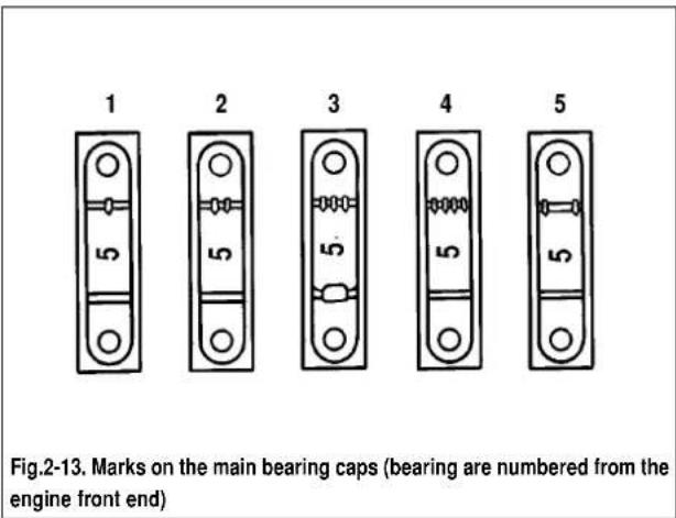
text_image
1 2 3 4 5 Fig.2-13. Marks on the main bearing caps (bearing are numbered from the engine front end)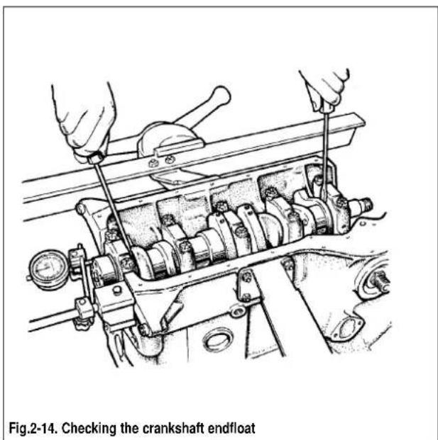
text_image
Fig.2-14. Checking the crankshaft endfloat
natural_image
Technical line drawing of a mechanical bearing housing assembly (no text or symbols)Fig.2-15. Crankshaft rear oil seal housing.
The lugs (arrowed) for centering the housing against the crankshaft flange
Locate the flywheel in position so that the marking (a cut-out) near the rim is against the No 4 cylinder crankpin axis. While holding the flywheel stationary with tool A.60330/R, bolt it to the crankshaft flange to the specified torque.
Using a ring compressor (tool 67.8125.9502), fit the pistons and connecting rods to the cylinders (Fig.2-17).
WARNING. The hole for gudgeon pin in the piston is 1.2 mm set off, so the arrows on the piston crown must face the timing belt end of the engine when inserting the pistons into the cylinders.
Press the big-end bearing shells into the connecting rods and caps. Guide the conrods and big-end caps onto the crankshaft journal, then tighten the connecting rod bolts. The big-end caps must be positioned so that the cylinder number on the cap is against the cylinder number on the connecting rod big-end.
Refit the crankshaft sprocket. Locate the oil pump shaft and secure it with the thrust flange.
Insert two centering pins into the cylinder block (Fig.2-17) and locate the cylinder head gasket over them.
WARNING. Always fit the new cylinder head gasket. Never re-use the old gasket.
Before refitting the gasket, remove any oil from the mating surfaces of the block and cylinder head. Make sure the gasket is perfectly clean and dry. Avoid any incidental oiling of the gasket.
Turn the crankshaft so that the pistons are midway in the cylinder bore.
Refit the cylinder head complete with the valves, exhaust manifold and intake pipe over the centering pins.

natural_image
Technical line drawing of a mechanical clutch assembly with no visible text or symbolsFig.2-16. Clutch dowels (arrowed black) and clutch housing centering pins (arrowed white)

natural_image
Technical line drawing of an engine cylinder head assembly (no text or labels)Fig.2-17. Fitting the pistons complete with piston rings using ring compressor; centering pins of the cylinder head (arrowed)
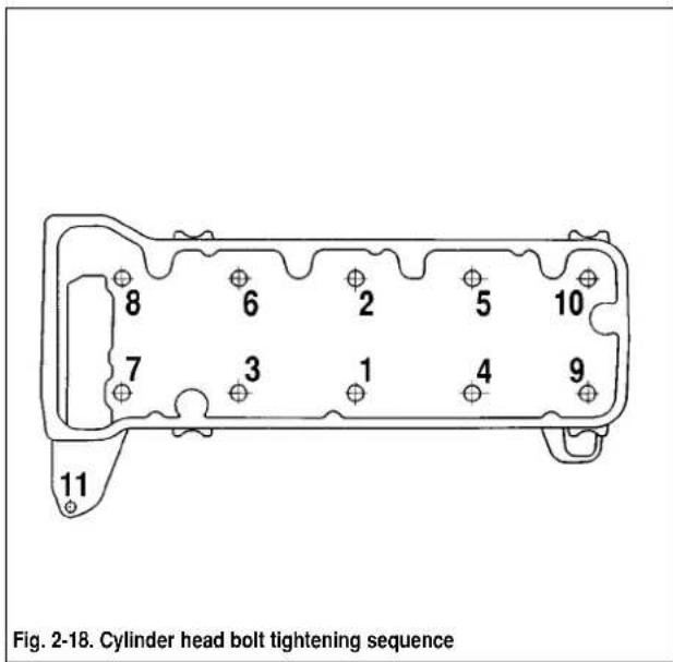
Tighten the cylinder head bolts in the established procedure (Fig.2-18) in four steps to ensure a reliable fit and exclude further tightening during vehicle servicing.
1st step - tighten the bolts 1-10 to 20 N·m(2 kgf·m);
2nd step - tighten the bolts 1-10 to 69.4-85.7 N·m
(7.1-8.7 kgf·m), while the bolt 11 to 31.36 - 39.1 N·m (3.2-3.99 kgf·m);
3rd step - turn the bolts 1-10 to 90°;
4th step - turn again all bolts 1-10 to further 90°.
WARNING. The cylinder head bolts can be re-used only when their length is not in excess of 120 mm, otherwise renew the bolt.
Before reassembly, immerse the bolts, thread and head, into engine oil. Allow the excess oil drip for at least 30 minutes. Remove all entrapped oil from the bolt bores in the cylinder head.
text_image
Fig. 2-18. Cylinder head bolt tightening sequence 8 6 2 5 10 7 3 1 4 9 11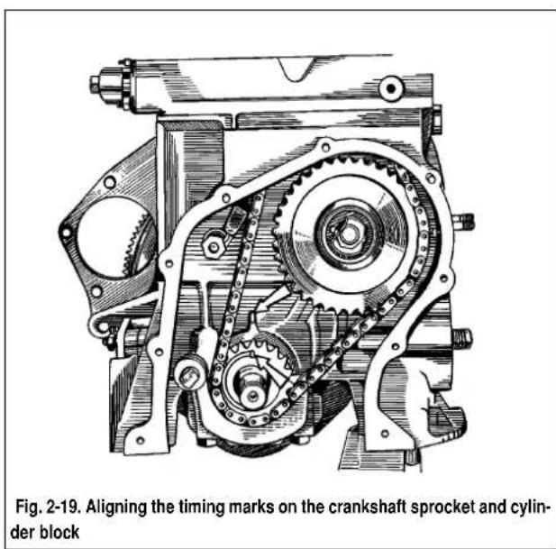
text_image
Fig. 2-19. Aligning the timing marks on the crankshaft sprocket and cylinder block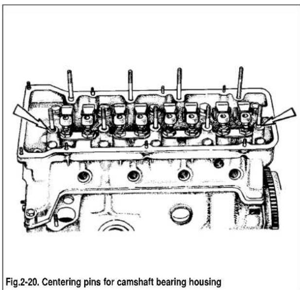
text_image
Fig.2-20. Centering pins for camshaft bearing housingTurn the flywheel so that the mark on the crankshaft sprocket is against the cylinder block mark (Fig.2-19).
Check to see the camshaft bearing housing centering pins are in position (Fig.2-20). Refit the sprocket to the camshaft complete with the bearing housing and turn the camshaft so that the timing mark in the sprocket is aligned against the mark on the bearing housing (Fig.2-21). Remove the sprocket and without changing the camshaft position, refit the bearing housing to the cylinder head so that the centering pins are in the respective bores of the bearing housing. Secure the bearing housing, tightening the nuts in the sequence as shown in Fig.2-22.
Refit the chain vibration damper.
Refit the camshaft timing chain:
- fit the chain onto the camshaft sprocket and position the sprocket so its TDC mark is aligned with the respective mark on the bearing housing (Fig.2-21). Do not tighten the sprocket bolt fully;
- fit the sprocket to the oil pump shaft, but do not tighten the retaining bolt fully;
- fit the chain tensioner shoe and tensioner, but do not tighten the cap nut so that the tensioner spring can compress the shoe; screw the chain stop pin into the cylinder block;
- turn the crankshaft two turns forward to ensure the chain tension required; check the indentations in the sprockets are aligned with TDC marks in the cylinder block and bearing housing (Fig.2-19 and Fig.2-21);
- when the marks are aligned, hold the flywheel stationary with tool A.60330/R (Fig.2-10), then tighten the sprocket securing bolts and chain tensioner cap nut to the torques specified, bend the sprocket bolt lock washers; should the marks are not aligned, repeat the chain refitting procedure.
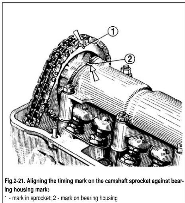
text_image
Fig.2-21. Aligning the timing mark on the camshaft sprocket against bearing housing mark: 1 - mark in sprocket; 2 - mark on bearing housing
text_image
7 3 2 6 8 4 1 5 9Fig.2-22. Camshaft bearing housing nuts tightening sequence
Adjust the clearance between the camshaft lobes and valve levers.
Refit the camshaft cover (Fig.2-23) complete with the gasket and oil seal to the cylinder block, do not tighten the retaining bolts and nuts fully. Using tool 41.7853.4010 centralize the cover against the crankshaft end, then tighten the retaining nuts and bolts to the torques specified.
Fit the alternator and oil pump pulley, then secure it with the nut.
Fit the oil filter complete with the gasket, manually screw it to the union on the cylinder block. Refit the crankcase vent oil separator, breather cover and secure the oil separator drain pipe with the clip.
Fit oil pump 1(Fig.2-24), then fit the oil sump with the gasket.
Fit the coolant pump, alternator bracket and alternator. Fit the belt around the pulleys and adjust the belt tension.
Fit the heater matrix supply pipe and cooling water jacket outlet pipe to the cylinder block. Secure the heater matrix drain pipe to the coolant pump and outlet pipe.
Fit the instrumentation sensors.
Fit the oil pump / distributor gear, followed by the ignition distributor. Insert the spark plugs, place spanner 67.7812.9515 on the spark plugs and tighten the spark plugs with a torque wrench to the torques specified.
Fit the fuel pump as outlined in section «Fuel system».
Fit the carburettor and reconnect the hoses. Cover the carburettor with a provisional cap.
WARNING. Never secure the carburettor (or tighten its retaining nuts) when it is warm.
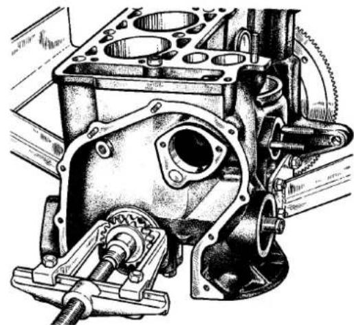
natural_image
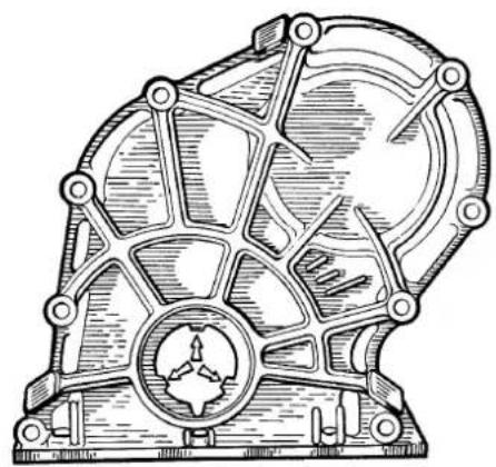
Technical line drawing of a mechanical component with symmetrical cutouts and mounting holes (no text or symbols)Fig.2-23. Timing cover
Projections (arrowed) for cover centering against crankshaft pulley hub
Fit the valve cover complete with the gasket and fuel piping bracket.
Fit the air cleaner, to do this secure the hoses to the air cleaner housing, fit the filter housing complete with the gasket to the carburettor, then fit the mounting plate and secure the housing with nuts. Locate the filter element and secure the air cleaner cover.
Reconnect the HT leads to the distributor and spark plugs.
Fill the engine with motor oil through the oil filler in the valve cover.
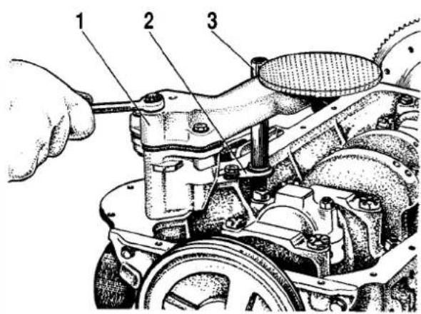
text_image
Technical diagram of a mechanical assembly with numbered parts labeled 1, 2, and 3Fig.2-24. Refitting the oil pump:
1 - oil pump; 2 - drain pipe lock; 3 - oil separator drain pipe