
MC3000 - DJ Equipment DENON - Free user manual and instructions
Find the device manual for free MC3000 DENON in PDF.

| Product Type | Professional DJ Controller |
| Brand | Denon |
| Model | MC3000 |
| Power Supply | DC 12V via included AC adapter (100-240V AC input) |
| Power Consumption | 16 W |
| Audio Inputs | 2x Stereo RCA (Line), 1x Balanced 1/4" TRS (Microphone) |
| Audio Outputs | 1x Balanced 1/4" TRS Master, 1x Unbalanced RCA Master, 1x 1/4" TRS Headphone |
| USB Audio Interface | 2-in/2-out stereo, 16-bit, 48 kHz sampling rate |
| MIDI Interface | USB MIDI 1.0, 1 in / 1 out, 16 channels |
| Jog Wheels | High resolution, touch sensitive, 2048 pulses per revolution |
| Deck Control | 4 decks via layer switching (A/C and B/D) |
| Included Software | Virtual DJ LE (Americas) or TRAKTOR LE 2 (Europe/Asia) |
| ASIO Driver | Provided for Windows low-latency operation |
| Channel Faders | 45 mm slim type faders |
| Crossfader | 45 mm fader, user-replaceable |
| Equalizer | 3-band isolator per channel (HI/MID/LOW) |
| Effects | Separate FX controls per deck, assignable to effect slots |
| Sampler | Control sampler without switching deck layer (4 sample slots per side) |
| Ducking | Automatic microphone ducking to attenuate background music |
| LINE TO MASTER | Backup audio input for external devices when computer is unavailable |
| Construction | High-grade steel cabinet with self-illuminating rubber buttons |
| Safety Certifications | FCC Class B, CE, WEEE compliant |
| Operating Temperature | +5 °C to +35 °C |
| Operating Humidity | 25% to 85% |
Frequently Asked Questions - MC3000 DENON
User questions about MC3000 DENON
0 question about this device. Answer the ones you know or ask your own.
Ask a new question about this device
Download the instructions for your DJ Equipment in PDF format for free! Find your manual MC3000 - DENON and take your electronic device back in hand. On this page are published all the documents necessary for the use of your device. MC3000 by DENON.
USER MANUAL MC3000 DENON
Professional DJ Controller
MC3000
Owner's Manual

CAUTION
RISK OF ELECTRIC SHOCK
DO NOT OPEN

CAUTION:
TO REDUCE THE RISK OF ELECTRIC SHOCK, DO NOT REMOVE COVER (OR BACK). NO USER-SERVICEABLE PARTS INSIDE. REFER SERVICING TO QUALIFIED SERVICE PERSONNEL.

The lightning flash with arrowhead symbol, within an equilateral triangle, is intended to alert the user to the presence of uninsulated "dangerous voltage" within the product's enclosure that may be of sufficient magnitude to constitute a risk of electric shock to persons.

The exclamation point within an equilateral triangle is intended to alert the user to the presence of important operating and maintenance (servicing) instructions in the literature accompanying the appliance.
IMPORTANT TO SAFETY
WARNING:
To reduce the risk of fire and electric shock, this apparatus should not be exposed to rain or moisture and objects filled with liquids, such as vases, should not be placed on this apparatus.
CAUTION
- Handle the power supply cord carefully
Do not damage or deform the power supply cord. If it is damaged or deformed, it may cause electric shock or malfunction when used. When removing from wall outlet, be sure to remove by holding the plug attachment and not by pulling the cord.
- Do not open the rear cover
In order to prevent electric shock, do not open the top cover.
If problems occur, contact your DENON DEALER.
- Do not place anything inside
Do not place metal objects or spill liquid inside the system.
Electric shock or malfunction may result
Please, record and retain the Model name and serial number of your set shown on the rating label.
Model No. MC3000
Serial No.
FCC INFORMATION (For US customers)
1. COMPLIANCE INFORMATION
Product Name: Professional DJ Controller
Model Number: MC3000
This product complies with Part 15 of the FCC Rules. Operation is subject to the following two conditions: (1) this product may not cause harmful interference, and (2) this product must accept any interference received, including interference that may cause undesired operation.
Denon Professional div. D&M Professional
1100 Maplewood Drive Itasca, IL 60143
Tel. 630-741-0330
2. IMPORTANT NOTICE: DO NOT MODIFY THIS PRODUCT
This product, when installed as indicated in the instructions contained in this manual, meets FCC requirements. Modification not expressly approved by DENON may void your authority, granted by the FCC, to use the product.
3. NOTE
This product has been tested and found to comply with the limits for a Class B digital device, pursuant to Part 15 of the FCC Rules. These limits are designed to provide reasonable protection against harmful interference in a residential installation.
This product generates, uses and can radiate radio frequency energy and, if not installed and used in accordance with the instructions, may cause harmful interference to radio communications. However, there is no guarantee that interference will not occur in a particular installation. If this product does cause harmful interference to radio or television reception, which can be determined by turning the product OFF and ON, the user is encouraged to try to correct the interference by one or more of the following measures:
• Reorient or relocate the receiving antenna.
- Increase the separation between the equipment and receiver.
- Connect the product into an outlet on a circuit different from that to which the connected.
- Consult the local retailer authorized to distribute this type of product or an experienced radio, technician for help.
For Canadian customers:
This Class B apparatus complies with Canadian ICES-003.
IMPORTANT SAFETY INSTRUCTIONS
READ BEFORE OPERATING EQUIPMENT
This product was designed and manufactured to meet strict quality and safety standards. There are, however, some installation and operation precautions which you should be particularly aware of.
-
Read these instructions.
-
Keep these instructions.
-
Heed all warnings.
-
Follow all instructions.
-
Do not use this apparatus near water.
-
Clean only with dry cloth.
-
Do not block any ventilation openings. Install in accordance with the manufacturer's instructions.
-
Do not install near any heat sources such as radiators, heat registers, stoves, or other apparatus (including amplifiers) that produce heat.
-
Do not defeat the safety purpose of the polarized or grounding-type plug. A polarized plug has two blades with one wider than the other. A grounding type plug has two blades and a third grounding prong. The wide blade or the third prong are provided for your safety. If the provided plug does not fit into your outlet, consult an electrician for replacement of the obsolete outlet.
-
Protect the power cord from being walked on or pinched particularly at plugs, convenience receptacles, and the point where they exit from the apparatus.
-
Only use attachments/accessories specified by the manufacturer.
-
Use only with the cart, stand, tripod, bracket, or table specified by the manufacturer, or sold with the apparatus. When a cart is used, use caution when moving the cart/apparatus combination to avoid injury from tip-over.
-
Unplug this apparatus during lightning storms or when unused for long periods of time.
-
Refer all servicing to qualified service personnel. Servicing is required when the apparatus has been damaged in any way, such as power-supply cord or plug is damaged, liquid has been spilled or objects have fallen into the apparatus, the apparatus has been exposed to rain or moisture, does not operate normally, or has been dropped.

CAUTION:
(English)
To completely disconnect this product from the mains, disconnect the plug from the wall socket outlet.
The mains plug is used to completely interrupt the power supply to the unit and must be within easy access by the user.
VORSICHT:
(Deutsch)
- DECLARATION OF CONFORMITY (English)
We declare under our sole responsibility that this product, to which this declaration relates, is in conformity with the following standards:
IN CONFORMY WITH THE FOLLOWING STANDARDS. EN60950-1, EN55022, EN55024, EN61000-3-2 and EN61000-3-3.
Following the provisions of Low Voltage Directive 2006/95/EC and EMC Directive 2 EC, the EC regulation 1275/2008 and its frame work Directive 2009/125/EC for Energy-related Products (ErP).
A division of D&M Europe B.V.
Beemdstraat 11
5653 MA Eindhoven
The Netherlands
A NOTE ABOUT RECYCLING:
This product's packaging materials are recyclable and can be reused. Please dispose of any
materials in accordance with the local recycling regulations. When discarding the unit, comply with local rules or regulat
Batteries should never be thrown away or incinerated but disposed of in accordance with the local regulations concerning battery disposal.
This product and the supplied accessories, excluding the batteries, constitute the applicable product according to the WEEE directive.
HINWEIS ZUM RECYCLING:
Cautions on handling
Connections
| Preparations | 3 |
| Cables used for connection | 3 |
| Input terminal connection | 3 |
| Connecting a microphone/external devices | 3 |
| Output terminal connections | 3 |
| Outputting to an amplifier/powered speakers and recording devices | 3 |
| Connecting to a computer | 4 |
| Connecting the power cord | 4 |
Installing and setting up supplied software
| Installing the ASIO driver (Windows only) | 5 |
| Starting up | 7 |
| About the control panel screen | 7 |
| Installing TRAKTOR LE 2 | 8 |
| Installation onto a Mac computer | 8 |
| Installation onto a Windows computer | 8 |
| Installing Virtual DJ LE | 9 |
| Installation into Mac computers | 9 |
| Installation into Windows computer | 9 |
| Basic operation | 10 |
Basic operation
Turning the power on 10
Turning the power off
Adjusting the volume of the master level
Microphone input
Adjusting the microphone input level
Headphone monitor
LINE TO MASTER function
Adjusting the level balance of lines 1/2 11
Adjusting the volume of lines 1/2
Adjusting the sensitivity of the touch sensor
Jog wheel lock function
Locking the jog wheel 12
Cancelling the jog wheel lock 12
USB settings 12
| USB AUDIO Input/Output | 12 |
| MIDI command input/output | 13 |
| MIDI channel assignment | 13 |
| Switching MIDI input/output channels | 14 |
| Setting the MIDI command transmission interval time | 14 |
| MIDI command list | 15 |
Part names and functions 18
| Top panel | 18 |
| 1 Audio input/output part | 18 |
| 2 TRAKTOR LE 2/PRO 2 | 19 |
| 3 Virtual DJ LE/PRO | 24 |
| Front panel | 29 |
| Rear panel | 29 |
| Troubleshooting | 30 |
| Specifications | 31 |
| Index | 32 |
| Signal system chart | 33 |
Accessories
Check that the following parts are supplied with the product.
① Quick setup guide .... 1
② Mapping guide .... 1
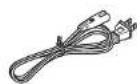
③ Power cord 1
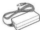
④ AC adaptor
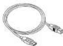
⑤ USB cable 1
⑥ CD-ROM
• MC3000 Resource CD-ROM 1
• DJ software (U.S.A and Canada models)
Virtual DJ LE 1
⑦ DVD-ROM (European, U.K and Asia/Pacific models)
• DJ software (TRAKTOR LE 2)....1
⑧ Warranty (for North America model only)....1
③
U.S.A and Canada models

European,U.K and Asia/
Pacific models
④
⑤
NOTE
Conduction noise or interference noise may cause the unit to
malfunction. Therefore, when connecting this device to a computer, connect using the USB cable included.
About this manual
Symbols


NOTE
This symbol indicates a reference page on which related information is described.
This symbol indicates a supplementary information and tips for operations.
This symbol indicates points to remember operations or function limitations.
□Illustrations
Note that the illustrations in these instructions are for explanation purposes and may differ from the actual unit.
Main features
1. Reliable design
• High grade steel cabinet and self-illuminating rubber buttons.
- Equipped with a LINE TO MASTER function that enables backup if the computer freezes, or when switching users (page 11).
2. USB MIDI controller
- Equipped with a physical controller function that controls DJ software.
- Design layout optimized for operations with TRAKTOR LE 2/PRO 2 and Virtual DJ LE/PRO.
- Easy operations for video effect and video cross fader settings in Virtual DJ LE/PRO.
- Equipped with a deck layer function that can control four decks separately.
- Equipped with a high resolution jog wheel with 2,048 pulses supporting the touch sensor function.
- Sampler can be controlled without switching the deck layer.
- Equipped with large CUE/PLAY buttons that can be pressed easily.
- Equipped with the SYNC button that can immediately synchronize beats for two decks.
- Separate FX controls for individual decks.
3. USB AUDIO interface
• High sound quality design that supports sampling frequency of 48 kHz.
• Supports stereo 2in-2out for stereo audio
- Supplied with ASIO drivers for low latency (1 page 5).
4. Others
- Equipped with a ducking function that attenuates background sounds during microphone operation (page 10).
• Supplied with DJ software.
Cautions on handling
• Before turning the power switch on
Check once again that all connections are correct and that there are no problems with the connection cables.
- Power is supplied to some of the circuitry even when the unit is set to the standby mode. When going on vacation or leaving home for long periods of time, be sure to unplug the power cord from the power outlet.
- About condensation
If there is a major difference in temperature between the inside of the unit and the surroundings, condensation (dew) may form on the operating parts inside the unit, causing the unit not to operate properly.
If this happens, let the unit sit for an hour or two with the power turned off and wait until there is little difference in temperature before using the unit.
• Cautions on using mobile phones
Using a mobile phone near this unit may result in noise. If that occurs, move the mobile phone away from this unit when it is in use.
- Moving the unit
Turn off the power and unplug the power cord from the power outlet. Next, disconnect the connection cables to other system units before moving the unit.
- About care
- Wipe the cabinet and control panel clean with a soft cloth.
- Follow the instructions when using a chemical cleaner.
- Benzene, paint thinner or other organic solvents as insecticide may cause material changes and discoloration if brought into contact with the unit, and should therefore not be used.
Connections
NOTE
- Do not plug in the power cord until all connections have been completed.
- When making connections, also refer to the operating instructions of the other components.
- Insert the plugs securely. Loose connections will result in the generation of noise.
- Be sure to connect the left and right channels properly (left with left, right with right).
- Connect the cables to the correct input and output terminals.
- Do not bundle power cords together with connection cables. Doing so can result in humming or noise.
Preparations
Cables used for connection
Select the cables according to the equipment being connected.
☐For RCA input/output terminals

For USB terminal

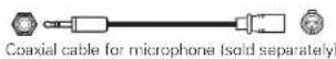
☐For coaxial microphone input
☐For master output terminals
Input terminal connection
Connecting a microphone/external devices

Output terminal connections
Outputting to an amplifier/powered speakers and recording devices

Connecting to a computer
Use the supplied USB cable to connect the unit with a computer so that USB MIDI and USB AUDIO signals can be sent and received.

□Compatible computers
• Computers running the following computer OS versions can be connected to this unit.
• Mac OS X 10.6 or later
• Windows XP SP3 or later (32 Bit only)
• Windows Vista SP2 or later (32 or 64 Bit)
• Windows 7 (32 or 64 Bit)
Computers running other OS versions may not be compatible with the USB MIDI. For this reason, such computers may function abnormally after connecting by USB to this unit.
• Mac, Mac OS is a registered trademark or trademark of Apple Inc.
in the United States and/or other countries
- Windows is a registered trademark or trademark of Microsoft Corporation in the United States and/or other countries.
□Automatic driver installation
When you connect the unit to a computer, drivers for the unit are automatically installed in the computer.
When this unit is connected to a Windows computer, the following message is shown at the bottom right of the screen.

Once installation is completed, a message "Your new hardware is installed and ready to use." appears as shown, and you can operate the unit.

- For Mac OS, the unit can be used immediately after connecting.
Connecting the power cord
Insert the supplied AC adapter DC plug into the DC IN jack of the unit and then insert the power plug to the outlet.
NOTE
Insert the plug fully and securely into the socket. Incomplete connection to the power supply may cause damage to the unit, or noise.


To prevent the DC plug from disconnecting, it is recommended that you should anchor the power cord to the AC adapter cable holder. Use a Phillips screwdriver to secure it.
Installing and setting up supplied software
Installing the ASIO driver (Windows only)
Use the following steps to install the supplied ASIO drivers.
- When using a Mac, no installation is required.
1 Insert the supplied "MC3000 Resource CD-ROM" into the computer.
The browse screen for the disc drive is displayed.
- If the browse screen is not displayed, click the disc drive on My Computer.
Click "Asio Driver Installation".
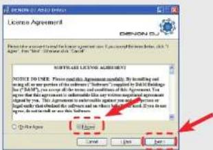
The ASIO Driver Setup Wizard is launched. Click "Next >".

3 The license agreement screen appears. If you agree, select "I Agree".
The "Next >" can now be selected.
Click "Next>".
4 A screen for verifying the folder in which the ASIO driver is to be installed appears.
Click "Next>".

By default, the ASIO driver is installed in "C:\Program Files\DENON_DJ\ADDJASIO\".
To change this location, click "Browse" and select a different folder. Choose "Everyone" if everyone uses the computer on which the update program is to be installed, "Just me" if you are the only user.
Installing the ASIO driver (Windows only)
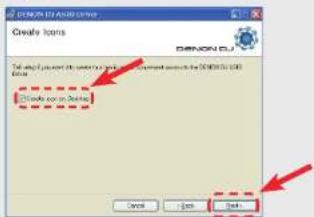
5 A screen for verifying whether or not to create a desktop shortcut appears.
To create a shortcut, check the check box and click "Next >".
6 The installation start screen is displayed. Click "Next >".
Installation begins.
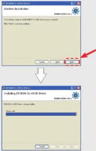
7 When the following installation completion screen is displayed, click "Close".

Uninstalling
The software can be uninstalled from control panel on the computer.
Starting up
When the DENON DJ ASIO driver "ASIO Control Panel" is opened from the DJ software or desktop icon, the DENON DJ ASIO driver appears in the ASIO Control Panel.
About the control panel screen
Installing the ASIO driver (Windows only)
① Devices (Device list)
This window is used for automatically displaying all connected DENON DJ devices in a list. (Example: MC3000)
- When you select a device you want to set from this list, the current settings of the selected device appear in a window ⑦ ("Device Description").
- If you double-click a device, the ASIO device status is switched from "Enable" to "Disable" or vice versa.
• ASIO device status
Enable
A check mark appears on the left side of a device name and the name is highlighted (bold).
Disable
The check mark on the left side of a device name is removed and the device name is displayed in lightface.

- You can select one device at a time.
- You can set multiple devices to enable at the same time.
② Enable/Disable
This button is used for switching a device selected in 1 (Devices) to enable or disable as an ASIO device.

The ASIO device status can also be switched by double-clicking the device name displayed in 1 (Devices).
3 Audio Buffer Size
Use this slider to adjust the buffer size.
NOTE
- The range of values is 88 to 2048 (sample units), in steps of 1 ms.
- When you set multiple devices to enable as ASIO devices, the same setting values apply to all ASIO devices.
④ OK/Cancel
OK:
Use this button to close the ASIO control panel, reflecting the changes to the settings.
Cancel:
Use this button to close the ASIO control panel without reflecting the changes to the settings.
⑤ Bit Resolution
Selected bit resolution is displayed.
6 Sampling Rate
The sampling rate selection is displayed here. The frequencies with which the DENON DJ ASIO driver is compatible are as follows: - 44.1 kHz/48 kHz/88.2 kHz/96 kHz - This device only supports 48 kHz.
⑦ Device Description
This is the area in which information for the device selected in the device information list is displayed.
The following are displayed:
- Device Name
- Unit Number
- Software Version
• Audio input channels
• Audio output channels
• Sampling frequency
• Max bit resolution
- Audio buffer size
NOTE
If the device's information cannot be acquired, “-” (hyphens) are displayed for all items.
Installing TRAKTOR LE 2
Use the following steps to install the DJ software "TRAKTOR LE 2" in the supplied DVD-ROM.
Installation onto a Mac computer
1 Insert DVD-ROM "TRAKTOR LE 2" into your computer.
The TRAKTOR LE 2 disc icon is displayed on the desktop.
2 Double-click the TRAKTOR LE 2 disc icon.
Files contained in the TRAKTOR LE 2 DVD are displayed for browsing.
3 Double-click "Traktor Installer". A window opens and the TRAKTOR LE 2 installation starts.
- Select Complete installation or Custom installation to start installation. If you are unsure about the Custom installation, select the Complete installation option.
4 Follow each step in the installation screen for installation.
5 When the installation completes, close the installation screen.

- After the installation, activate the software. For information about how to activate the software, see Service Center Manual, which is located in the Documentation folder under the Service Center folder that is created during the installation.
- It is recommended that you use the latest version of the TRAKTOR LE 2 software.
- For information about how to use the DJ software, see the instruction manual for the DJ software or the help menu.
- The serial number is printed on the back of the DVD-ROM case.
- TRAKTOR LE 2 is an NI software. To install and use the software, you have to accept the software license agreement.
D&M shall not be responsible for any problems with your computer and other software that may arise from the installation and use of TRAKTOR LE 2.
Installation onto a Windows computer
1 Insert DVD-ROM "TRAKTOR LE 2" into your computer.
The browse screen for the disc drive is displayed.
- If the browse screen is not displayed, click the disc drive on My Computer.
2 Double-click "Traktor Setup.exe". A window opens and the TRAKTOR LE 2 installation starts.
- Select Complete installation or Custom installation to start installation. If you are unsure about the Custom installation, select the Complete installation option.
3 Follow each step in the installation screen for installation.
4 When the installation completes, close the installation screen.

- After the installation, activate the software. For information about how to activate the software, see Service Center Manual, which is located in the Documentation folder under the Service Center folder that is created during the installation.
- It is recommended that you use the latest version of the TRAKTOR LE 2 software.
- For information about how to use the DJ software, see the instruction manual for the DJ software or the help menu.
• The serial number is printed on the back of the DVD-ROM case. - TRAKTOR LE 2 is an NI software. To install and use the software, you have to accept the software license agreement.
D&M shall not be responsible for any problems with your computer and other software that may arise from the installation and use of TRAKTOR LE 2.
Installing Virtual DJ LE
Use the following steps to install the DJ software "Virtual DJ LE" in the supplied CD-ROM.
Installation into Mac computers
1 Insert CD-ROM "Virtual DJ LE" into your computer.
The Virtual DJ icon is displayed on the desktop.
2 Double-click the Virtual DJ LE icon.
Files contained in the Virtual DJ LE are displayed for browsing.
3 Double-click "install_virtualdj_le_mc3000_vxxx.pkg".
A window opens and the Virtual DJ LE installation starts.
- "xx" represents the version number.
[Example]
Ver.7.0.5: install_virtualdj_le_mc3000_v7.0.5.pkg
4 Follow each step in the installation screen for installation.
5 When the installation completes, close the installation screen.
The image is too blurry to recognize any text content.
- When you start Virtual DJ LE for the first time after installation, follow the instructions on the screen to enter the product serial number.
- It is recommended that you use the latest version of Virtual DJ.
- For information about how to use the DJ software, see the instruction manual for the DJ software or the help menu.
• The serial number is printed on the back of the CD-ROM case. - Virtual DJ is an Atomix Productions software. To install and use the software, you have to accept the software license agreement. D&M shall not be responsible for any problems with your computer and other software that may arise from the installation and use of Virtual DJ LE.
Installation into Windows computer
1 Insert CD-ROM "Virtual DJ LE" into your computer.
The browse screen for the disc drive is displayed.
- When the browse screen is not displayed, click the disc drive on My Computer.
2 Double-click "install_virtualdj_le_mc3000_vxxx.msi".
A window opens and the Virtual DJ LE installation starts.
- "xx" represents the version number.
[Example]
Ver.7.0.5: install_virtualdj_le_mc3000_v7.0.5.msi
3 Follow each step in the installation screen for installation.
4 When the installation completes, close the installation screen.
The Virtual DJ LE icon is created on the desktop.
1
- When you start Virtual DJ LE for the first time after installation, follow the instructions on the screen to enter the product serial number.
- It is recommended that you use the latest version of Virtual DJ.
- For information about how to use the DJ software, see the instruction manual for the DJ software or the help menu.
- The serial number is printed on the back of the CD-ROM case.
- Virtual DJ is an Atomix Productions software. To install and use the software, you have to accept the software license agreement. D&M shall not be responsible for any problems with your computer and other software that may arise from the installation and use of Virtual DJ LE.
Basic operation
Top panel

Front panel
Rear panel
This section describes operations of the unit without using the DJ software.
- For information about how to operate the DJ software, see the instruction manual for the DJ software or the help menu.
- For information about the buttons on the unit for operating the DJ software and their functions, see the following pages.
• TRAKTOR LE 2/PRO 2……Page 19 – 23
• Virtual DJ LE/PRO……Page 24 – 28
Basic operation
Turning the power on
Press POWER.
DECK CHG. lights, and the power switches on
Turning the power off
Press POWER.
DECK CHG, goes out, and the power switches off.
NOTE
There is no function on this device for automatically switching off the power supply when the unit is not used for a prolonged period.
If you do not intend to use this device for a prolonged period, for safety either switch off the power supply, or remove the AC adaptor plug from the wall socket.
Adjusting the volume of the master level
Turn MASTER LEVEL.
Microphone input
Adjusting the microphone input level
Turn MIC LEVEL.
□Enabling the ducking function
The ducking function detects the microphone input and attenuates the audio signal level of the master output. This prevents microphone audio from being inaudible under loud music.
Press DUCKING.
DUCKING lights up.
Headphone monitor
Make sure that your headphone plug is already inserted in the Headphone jack.
1 Press CUE for each channel to select the source to monitor.
The selected CUE lights up.
2 Turn MONITOR PAN to adjust the balance of the cue volume and master volume.
3 Turn PHONES to adjust the headphone volume.
NOTE
When using headphones, be careful not to turn the volume too high.


LINE TO MASTER function
Even if this device is not connected to a computer, the audio from external devices such as CD players connected to the line 1/2 input terminals can be output as the master level. Therefore, sound can be output without interruption if the computer needs to be replaced or restarted because of a crash or freeze, or when charging DJ's. - DJ changeover can be done smoothly by using this function. - DJ software audio and audio such as CD player audio can be mixed and output.
[Example]
1 After the DJ has finished performing, lower the channel fader knob while rotating LINE TO MASTER LEVEL to the right.
The volume of the audio being output from the computer lowers, and audio from an external device is output.
2 Replace the computer while the audio from the external device is being output.
3 When the next DJ is ready, turn the LINE TO MASTER LEVEL to the left, and raise the channel fader knob.
The volume of the audio being output from the external device lowers, and audio from the computer is output.
Adjusting the level balance of lines 1/2
Turn LINE TO MASTER PAN.
Adjusting the volume of lines 1/2
Turn LINE TO MASTER LEVEL.
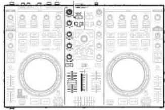
Adjusting the sensitivity of the touch sensor
The unit can control the sensitivity of the touch sensor for the Jog wheel in 9 steps (-4 - 0 - +4).
- “-4” is the lowest sensitivity, and “+4” is the highest sensitivity. - The default setting is “0”.
1 While holding down LOAD A/C, LOAD B/D and CF MODE, press POWER to turn on the power supply.
2 Press CF MODE, and switch the jog wheel that you want to adjust. CUE lights on the selected jog wheel side.
3 Turn SEL. to adjust the sensitivity. The button lights according to the set sensitivity.
| Buttons | CUE1 | CUE2 | CUE3 | CUE4 | AUTO LOOP | EFX.1 | EFX.2 | EFX.3 | EFX.4 |
| Sensitivity | -4 | -3 | -2 | -1 | 0 | +1 | +2 | +3 | +4 |
- If the jog wheel on the DECK side being adjusted detects a touch, the jog wheel changes from red to blue.
4 Press SEL. The adjusted sensitivity is saved.
5 Press SHIFT for DECK A or B. The mode switches back from the sensitivity adjustment mode to the normal mode.

Jog wheel lock function
Some DJ's prefer not to play using the jog wheel. This function can also be used to prevent accidental operation of the jog wheel while the DJ is playing.
In this case, use the following steps to lock the jog wheel. During playback, the touch sensor and rotation operation are disabled.
- Even if the jog wheel is locked using this function, the touch sensor and rotation operation are enabled when there is nothing being played back. Therefore, the jog wheel can be used for searching when tracks are not being played back.
Locking the jog wheel
Hold down SHIFT for DECK A or B, and press VINYL MODE for the jog wheel that you want to lock.
VINYL MODE flashes, and the jog wheel is locked
Cancelling the jog wheel lock
When the jog wheel is locked, hold down SHIFT for DECK A or B, and press VINYL MODE for the jog wheel that you want to release.
The jog wheel lock is released, and the jog wheel returns to the previous state (either VINYL mode or BEND model).
USB settings
USB AUDIO Input/Output
This device is equipped with a sound card function that enables a maximum of 4 channels (stereo, 2 input 2 output) of USB AUDIO input and output.
The audio signals from lines 1/2 are output to a computer.
Further, the DJ software mixer output is output from the master output terminal or headphone terminal of this device.
- USB 1/2 channel input—DJ software master
- USB 3/4 channel input—DJ software cue monitor
• USB 1/2 channel output—MC3000 line 1 audio signal
• USB 3/4 channel output—MC3000 line 2 audio signal
MIDI command input/output
This unit is equipped with a USB MIDI command input/output function. This function enables the unit to control the DJ software in the computer, and lights the main unit display (LEDs).
- If TRAKTOR LE 2/PRO 2 and Virtual DJ LE/PRO are used normally, there is no need to switch MIDI command settings or the MIDI channel. Doing so may cause undesired operation or no operation at all. Set when TRAKTOR LE 2/PRO 2 and Virtual DJ LE/PRO are customized for expanded operation, or when other DJ software is used.
MIDI channel assignment
Most of the controls in this device support the MIDI control function.
Each control is assigned to a MIDI channel as shown in the following block.
• The MIDI channel is made up of 4 channels.
Range of CH1, CH5, CH9 and CH13
- When DECK CHG. A is lit, it is enabled
DECK CHG. A
- When DECK A/C is lit, it is enabled
DECK A/C
natural_image
Front view of a vintage electronic device with dual circular ports and control knobs (no visible text or symbols)Range of CH2, CH6, CH10 and CH14
- When DECK CHG. C is lit, it is enabled
DECK CHG. C

- When DECK A/C is lit, it is enabled
DECK A/C
natural_image
Front view of a vintage oscilloscope with dual dials and control knobs (no visible text or labels)Range of CH3, CH7, CH11 and CH15
- When DECK CHG. B is lit, it is enabled
DECK CHG. B

- When DECK B/D is lit, it is enabled
DECK B/D
natural_image
Front view of a dual oscilloscope interface with measurement scales and display screens (no visible text or symbols)Range of CH4, CH8, CH12 and CH16
- When DECK CHG. D is lit, it is enabled
DECK CHG. D

natural_image
Front view of an analog oscilloscope with display and control knobs (no readable text or symbols)- When DECK B/D is lit, it is enabled
DECK B/D

natural_image
Front view of a dual electronic device with circuit patterns and control knobs (no visible text or symbols)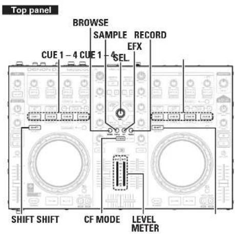
Switching MIDI input/output channels
1 Press one of BROWSE/SAMPLE/EFX/RECORD while holding down SHIFT.

The CUE that corresponds to the MIDI channel lights, and the MIDI channel is switched as shown below.
• The MIDI channel is made up of 4 channels.
[Lights CUE]
CUE 1 : CH 1-4
CUE 3 : CH 9-12
[MIDI channel switching]
BROWSE : CH1-4
EFX : CH 9-12
CUE 2 : CH 5 - 8
CUE 4 : CH 13 - 16
SAMPLE : CH5-8
RECORD : CH 13-16
2 Release SHIFT.
The mode returns to normal mode from the channel setting mode.
□Checking the settings
Press CF MODE while holding down SHIFT.
The CUE corresponding to the current MIDI channel flashes.

The following buttons and switches do not support MIDI output.
• MIC LEVEL
• MONITOR PAN
• MONITOR PHONES
• LINE TO MASTER PAN
• LINE TO MASTER LEVEL
• MASTER LEVEL
- DECK/MASTER
MIDI command input/output
Setting the MIDI command transmission interval time
Depending on the computer specifications and OS type, the computer may not be able to receive the MIDI commands transmitted from this unit correctly.
In this case, use the following operation to set the MIDI command transmission interval time to a suitable value.
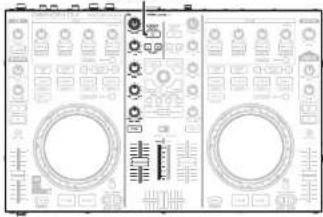
1 While pressing BROWSE, RECORD and CF MODE together, press POWER.
The power switches on, the LEVEL METER lights, and the unit switches to the setting mode for MIDI command transmission interval time.
2 Turn SEL.
The relationship between the level display position of the LEVEL METER and the MIDI command transmission interval time is as shown in the diagram on the left.
[Setting value]

[Example]
• The factory setting is 4 msec.

Press SEL.
The MIDI command transmission interval time is entered.

Press SHIFT on DECK A or B.
The settings are completed, and unit exits the setting mode.
MIDI command input/output
MIDI command list
Send command
| Items | MIDI command | |||
| Command Number Value | ||||
| 1 | CUE (DECK A) | F# 1 | 1 C# -1 | |
| 2 | CUE (DECK C) 2 D -1 | |||
| 3 | DECK CHG. A 3 D# 1 | |||
| 4 | VINYL MODE 4 E -1 | |||
| 5 | CUE (DECK B) 5 F -1 | |||
| 6 | KEY LOCK 8 | |||
| 7 | CUE (DECK D) | 7 G -1 | ||
| 8 | DECK CHG. B 8 G# -1 | |||
| 9 | DECK CHG. C 9 A -1 | |||
| 10 | DECK CHG. D | C 0 | 10 | A# -1 |
| 11 | BEND + 12 | |||
| 12 | BEND - | 13 | C# 0 | |
| 13 | DECK A/C | 14 | D 0 | |
| 14 | DECK B/D | 15 D# 0 | ||
| 15 | EFX.2 SW (FX1) | 18 | F# 0 | |
| 16 | EFX.3 SW (FX1) | 19 | G 0 | |
| 17 | EFX.4 SW (FX1) | 20 C# 0 | ||
| 18 | EFX.1 SW (FX1) | 21 | A 0 | |
| 19 | CUE1 | 23 | B 0 | |
| 20 | CUT2 | 24 | C 1 | |
| 21 | CUT3 | 25 | C# 1 | |
| 22 | SAMP. MODE | 26 | D 1 | |
| 23 | CF MODE | NOTE ON : 0x8nNOTE OFF : 0x8n | 27 D# 1 | |
| 24 | CUES-8 MODE | 30 | F# 1 | |
| 25 | CUE4 | 32 C# 1 | ||
| 26 | SAMP.1 (LEFT) | 33 | A 1 | |
| 27 | SAMP.2 (LEFT) | 34 | A# 1 | |
| 28 | SAMP.2 (LEFT) | 35 | B 1 | |
| 29 | SAMP.4 (LEFT) | 36 | C 2 | |
| 30 | AUTO LOOP 29 F 1 | |||
| 31 | DUCKING | 42 | F# 2 | |
| 32 | TRACK SELECT KNOBSW | 40 E2 | ||
| 33 | FWD | 41 F2 | ||
| 34 | RCK | 48 | C 3 | |
| 35 | SAMP.1 (RIGHT) | 49 | C# 3 | |
| 36 | SAMP.2 (RIGHT) | 50 | D 3 | |
| 37 | SAMP.3 (RIGHT) | 51 D# 3 | ||
| 38 | SAMP.4 (RIGHT) | 52 | E 3 | |
| 39 | LOOP IN | 55 | G 3 | |
| 40 | LOOP OUT | 57 | A 3 | |
| 41 | CUE | 66 | F# 4 | |
| 42 | PLAY | 67 | G 4 | |
| 43 | CUE5 | 72 | C 5 | |
| 44 | CUE6 | 73 | C# 5 | |
| 45 | CUE7 | 74 | D 6 | |
| Items | MIDI command | |||
| Command Number Value | ||||
| 48 | CUER | NOTE ON: 0x3nNOTE OFF: 0xBnC7101 | 75 D# 5 | |
| 47 | JOG WHEEL TOUCH | 81 | A 5 | |
| 48 | EFX.2 SW IFX2I | 82 | A# 5 | |
| 49 | EFX.3 SW IFX2I | 83 | B 5 | |
| 50 | EFX.4 SW IFX2I | 84 | C 6 | |
| 51 | EFX.1 SW IFX2I | 85 | C# 6 | |
| 52 | FX ON 1 | 86 | D 6 | |
| 53 | FX ON 2 | 87 | D# 6 | |
| 54 | SHIFT (LEFT DECK) | 96 | C 7 | |
| 55 | SHIFT (RIGHT DECK) | 97 | C# 7 | |
| 56 | LOAD A | 98 | D 7 | |
| 57 | LOAD B | 99 D# 7 | ||
| 58 | BROWSER 100 | |||
| 59 | RECORD | F 7 | ||
| 60 | SAMPLE | 76 | E 5 | |
| 61 | EFX | 77 | F 5 | |
| 62 | LOOP CUT - | 06 A 7 | ||
| 63 | LOOP CUT + | 06 | A# 7 | |
| 64 | SYNC | 107 | B 7 | |
| 65 | JOG WHEEL FWD/REV | CC: 0xBn | 81 | Reverse 63 - 1Forward 65 - 127slow->fast• relative data |
| 66 | FILTER, KNOB (DECK BIIncrement/Decrement | 82 | ||
| 67 | FILTER, KNOB (DECK DIIncrement/Decrement | 83 | ||
| 68 | TRACK SELECT KNOBIncrement/Decrement | 84 | Increment 0Decrement 127 | |
| 69 | EFX1 KNOB (FX1IIncrement/Decrement | 85 | 0 - 127 | |
| 70 | EFX2 KNOB (FX1IIncrement/Decrement | 86 | ||
| 71 | EFX3 KNOB (FX1IIncrement/Decrement | 87 | ||
| 72 | EFX4 KNOB (FX1IIncrement/Decrement | 88 | ||
| 73 | EFX1 KNOB (FX2IIncrement/Decrement | 89 | ||
| 74 | EFX2 KNOB (FX2IIncrement/Decrement | 90 | ||
| 75 | EFX3 KNOB (FX2IIncrement/Decrement | 91 | ||
| 76 | FCFX4 KNOB (FX2IIncrement/Decrement | 92 | ||
| 77 | FILTER, KNOB (DECK AIIncrement/Decrement | 93 | ||
| 78 | FILTER, KNOB (DECK CIIncrement/Decrement | 94 | ||
MIDI command input/output
| Items | MIDI command | |||
| Command | Number | Value | ||
| 79 | EFX 1 KNOB (LEFT) in SAMP mode | CC: 0xBn | 48 | 0 - 127 |
| 80 | EFX 2 KNOB (LEFT) in SAMP mode | 49 | ||
| 81 | EFX 3 KNOB (LEFT) in SAMP mode | 50 | ||
| 82 | EFX 4 KNOB (LEFT) in SAMP mode | 51 | ||
| 83 | EFX.1 KNOB (RIGHT) in SAMP mode | 52 | ||
| 84 | EFX.2 KNOB (RIGHT) in SAMP mode | 53 | ||
| 85 | EFX.3 KNOB (RIGHT) in SAMP mode | 54 | ||
| 86 | EFX.4 KNOB (RIGHT) in SAMP mode | 55 | ||
| 87 | INPUT LEVEL (DECK A) | 1 | ||
| 88 | EQ HIGH VR (DECK A) | 2 | ||
| 89 | EQ MID VR (DECK A) | 3 | ||
| 90 | EQ LOW VR (DECK A) | 4 | ||
| 91 | FADER (for DECK A) | 5 | ||
| 92 | INPUT LEVEL (DECK C) | 7 | ||
| 93 | EQ HIGH VR (DECK C) | 8 | ||
| 94 | EQ MID VR (DECK C) | 9 | ||
| 95 | EQ LOW VR (DECK C) | 10 | ||
| 96 | FADER (DECK C) | 11 | ||
| 97 | INPUT LEVEL (DECK B) | 12 | ||
| 98 | EQ HIGH VR (DECK B) | 13 | ||
| 99 | EQ MID VR (DECK D) | 14 | ||
| 100 | EQ LOW VR (DECK D) | 15 | ||
| 101 | FADER (DECK B) | 16 | ||
| 102 | INPUT LEVEL (DECK D) | 17 | ||
| 103 | EQ HIGH VR (DECK D) | 18 | ||
| 104 | EQ MID VR (DECK D) | 19 | ||
| 105 | EQ LOW VR (DECK D) | 20 | ||
| 106 | FADER (DECK D) | 21 | ||
| 107 | CROSS FADER (AUDIO) | 22 | ||
| 108 | CROSS FADER (VIDEO) | 23 | ||
| 109 | Pitch Slider | 0xEn | 0xII (LSB) | 0xmm RMSB |
*n=MIDI CH=0-15
□Reception commands
| Items(Lit display (LED)) | MIDI command | |||
| Command Number Value | ||||
| 1 | VINYL MODE | CC : 0x8n | 25 | 6 |
| 2 | KEY LOCK 8 | |||
| 3 | SYNC 9 | |||
| 4 | CUE1 17 | |||
| 5 | CUE1 Dimmer 18 | |||
| 6 | CUE2 19 | |||
| 7 | CUE2 Dimmer 20 | |||
| 8 | CUE3 21 | |||
| 9 | CUE3 Dimmer 22 | |||
| 10 | CUE4 23 | |||
| 11 | CUE4 Dimmer 24 | |||
| 12 | SAMP.1 (LEFT) | |||
| 13 | SAMP.1 Dimmer (LEFT) | 26 | ||
| 14 | SAMP.2 (LEFT) | 27 | ||
| 15 | SAMP.2 Dimmer (LEFT) | 28 | ||
| 16 | SAMP.3 (LEFT) | 29 | ||
| 17 | SAMP.3 Dimmer (LEFT) | 31 | ||
| 18 | SAMP.4 (LEFT) | ON TRG : 74OFF TRG : 75Blink ON TRG : 76 | 32 | |
| 19 | SAMP.4 Dimmer (LEFT) | 33 | ||
| 20 | SAMP.1 (RIGHT) | 65 | ||
| 21 | SAMP.1 Dimmer (RIGHT) | 66 | ||
| 22 | SAMP.2 (RIGHT) | 67 | ||
| 23 | SAMP.2 Dimmer (RIGHT) | 68 | ||
| 24 | SAMP.3 (RIGHT) | 69 | ||
| 25 | SAMP.3 Dimmer (RIGHT) | 70 | ||
| 26 | SAMP.4 (RIGHT) | 71 | ||
| 27 | SAMP.4 Dimmer (RIGHT) | 72 | ||
| 28 | CUE5 48 | |||
| 29 | CUE5 Dimmer 49 | |||
| 30 | CUE6 50 | |||
| 31 | CUE6 Dimmer 51 | |||
| 32 | CUE7 52 | |||
| 33 | CUE7 Dimmer 53 | |||
| 34 | CUE8 54 | |||
| 35 | CUE8 Dimmer 55 | |||
| 36 | CUE | 38 | ||
MIDI command input/output
| Items(Lit display (LED)) | MIDI command | |||
| Command Number Value | ||||
| 37 | PLAY | CC : 0xBn | ON TRG : 74OFF TRG : 75Blink ON TRG : 76 | 39 |
| 38 | LOOP IN 36 | |||
| 39 | LOOP IN Dimmer 62 | |||
| 40 | LOOP OUT 64 | |||
| 41 | LOOP OUT Dimmer 42 | |||
| 42 | AUTO LOOP 43 | |||
| 43 | AUTO LOOP Dimmer 83 | |||
| 44 | EFX.1 Dimmer (FX1) | |||
| 45 | EFX.2 Dimmer (FX1) | |||
| 46 | EFX.3 Dimmer (FX1) | |||
| 47 | EFX.4 Dimmer (FX1) | |||
| 48 | EFX.1 Dimmer (FX2) | |||
| 49 | EFX.2 Dimmer (FX2) | |||
| 50 | EFX.3 Dimmer (FX2) | |||
| 51 | EFX.4 Dimmer (FX2) | |||
| 52 | 90 | |||
| 53 | FX ON 1 | 91 | ||
| 54 | EFX 1 IFX11 | 92 | ||
| 55 | EFX 2 IFX11 | 93 | ||
| 56 | EFX 3 IFX11 94 | |||
| 57 | EFX 4 IFX11 | 95 | ||
| 58 | EFX 1 IFX21 | 96 | ||
| 59 | EFX 2 IFX21 | 97 | ||
| 60 | EFX 3 IFX21 98 | |||
| 61 | EFX 4 IFX21 | 99 | ||
| 62 | ALL SLIDER/VOLUME/FADER REQUEST | 74 | 57 | |
| 63 | CUE IDECK AI | ON TRG : 80OFF TRG : 31 | 69 | |
| 64 | CUE Dimmer (DECK AI) | 70 | ||
| 65 | CUE IDECK CI | 75 | ||
| 66 | CUE Dimmer (DECK CI) | 76 | ||
| 67 | CUE IDECK BI | 81 | ||
| 68 | CUE Dimmer (DECK BI) | 82 | ||
| Items(Lit display (LED)) | MIDI command | |||
| Command Number Value | ||||
| 69 | CUE [DECK DI] | CC : 0xBn | ON TRG : 80OFF TRG : 31 | 87 |
| 70 | CUE Dimmer [DECK DI] | 88 | ||
| 71 | DUCKING | 89 | ||
| 72 | CF MODE [AUDIO] | 97 | ||
| 73 | CF MODE [VIDEO] | 98 | ||
| 74 | METER 4 [DECK AI | 10 | ||
| 75 | METER 5 [DECK AI | 11 | ||
| 76 | METER 6 [DECK AI | 12 | ||
| 77 | METER 7 [DECK AI | 13 | ||
| 78 | METER 8 [DECK AI | 14 | ||
| 79 | METER 9 [DECK AI | 15 | ||
| 80 | METER PEAK [DECK AI | 16 | ||
| 81 | METER 4 [DECK CI] | 26 | ||
| 82 | METER 5 [DECK CI] | 27 | ||
| 83 | METER 6 [DECK CI] | 28 | ||
| 84 | METER 7 [DECK CI] | 29 | ||
| 85 | METER 8 [DECK CI] | 30 | ||
| 86 | METER 9 [DECK CI] | 31 | ||
| 87 | METER PEAK [DECK CI] | 32 | ||
| 88 | METER 4 [DECK BI] | 42 | ||
| 89 | METER 5 [DECK BI] | 43 | ||
| 90 | METER 6 [DECK BI] | 44 | ||
| 91 | METER 7 [DECK BI] | 45 | ||
| 92 | METER 8 [DECK BI] | 46 | ||
| 93 | METER 9 [DECK BI] | 47 | ||
| 94 | METER PEAK [DECK BI] | 48 | ||
| 95 | METER 4 [DECK DI] | 58 | ||
| 96 | METER 5 [DECK DI] | 59 | ||
| 97 | METER 6 [DECK DI] | 60 | ||
| 98 | METER 7 [DECK DI] | 61 | ||
| 99 | METER 8 [DECK DI] | 62 | ||
| 100 | METER 9 [DECK DI] | 63 | ||
| 101 | METER PEAK [DECK DI] | 64 | ||
*n=MIDI CH=0-15
Part names and functions
Top panel
① Audio input/output part
This section describes the top panel in the following sections: ① Audio input/output part, ② TRAKTOR LE 2/PRO 2 and ③ Virtual DJ LE/PRO. Read descriptions for your DJ software. For buttons not explained here, see the page indicated in parentheses (1).
① Microphone input level adjustment knob (MIC LEVEL) …… (10)
② Ducking ON/OFF switch button
(DUCKING) (10)
When microphone input is detected, the volume other than the microphone volume output from the master is automatically attenuated.
3 PAN adjustment knob
(MONITOR PAN)....(10)
Adjusts the balance between the cue output from the headphones and master volume.
4 Headphone output volume adjustment knob (MONITOR PHONES) ...... (10)
⑤ Master output volume adjustment knob
(MASTER LEVEL) ....(10)
Adjusts the volume output from the master output terminal.
6 LINE TO MASTER PAN adjustment knob
(LINE TO MASTER PAN) ....(11)
Adjusts the volume balance between line 1 and line 2.
⑦ LINE TO MASTER Master output volume adjustment knob (LINE TO MASTER LEVEL) ..... (11)
Adjusts the volume of line 1 and line 2.
① Effects/sample adjustment knob (EFX.1/EFX.2/EFX.3/EFX.4)
③ SAMP the following operations differ depending on whether this is ON or OFF.
OFF: Uses the effects.
The operations differ depending on the TRAKTOR mode (ADVANCED EFX/CHAINED EFX).
EFX.1: Adjusts the effect balance
- Hold down ⑦ SHIFT and turn the knob, and the mode switches to the following setting mode.
• In the SINGLE FX MODE: Selects the effect type.
• In the GROUP FX MODE: Not available.
EFX.2/EFX.3/EFX.4
• In the SINGLE FX mode: Adjusts effect parameters
• In the GROUP FX mode Adjusts the effect level.
- Hold down ⑦ SHIFT and turn the knob, and the mode switches to the following setting mode.
• In the SINGLE FX MODE: Not available.
• In the GROUP FX MODE: Selects the effect type.
ON: Uses the sampler
EFX.1/EFX.2/EFX.3/EFX.4:
Adjusts the level of the sample slot.
- Hold down ⑦ SHIFT and turn the knob to adjust the cut off frequency of the sample slot.
② Effects ON/OFF switch button (EFX.1/EFX.2/EFX.3/EFX.4)
③ SAMP the following operations differ depending on whether this is ON or OFF. OFF: Uses the effects.
The operations differ depending on the TRAKTOR mode (ADVANCED EFX/CHAINED EFX).
EFX.1:
• In the SINGLE FX MODE: Switches the effects ON/OFF.
• In the GROUP FX MODE: Not available.
EFX.2/EFX.3/EFX.4:
• In the SINGLE FX MODE: Switches effect parameters ON/OFF.
• In the GROUP FX MODE: Switches the effect ON/OFF
Top panel
ON: Uses the sampler.
This function is enabled when the upgraded version TRAKTOR PRO 2 (sold separately) is used.)
EFX.1/EFX.2/EFX.3/EFX.4
Plays back the sample.
- Hold down ③ SAMP, and press this button to playback the sample slot trigger.
- Hold down ⑦ SHIFT and press this button to switch the sample slot filter ON/OFF.
- Press and hold ③ SAMP, and ⑦ SHIFT together and press this button to switch one shot or loop playback ON/OFF.
- Hold down 25 SEL. and press this button to load the file selected in the browser to the sample slot.
- Hold down 27 RECORD and press this button to copy the audio recorded in the lop recorder to the sample slot.
- Hold down 29 SAMPLE and press this button to load the loop from DECK A [BI] to the sample slot.
③ Sample mode switching button (SAMP.)
OFF: Switches to the effect mode. ①② EFX.
1-4 are used to operate the effects
ON: Switches to the sample deck mode 12
EFX.1-4 are used to operate the sample deck.
4 Loop point setting button
(LOOP IN/LOOP OUT)
Sets the loop in point and loop out point.
⑤ Auto loop and loop size adjustment buttons (AUTO LOOP -/+ )
• AUTO LOOP switches auto loop ON/OFF.
- Use -/+ to adjust the loop size.
- Hold down ⑦ SHIFT and press this button to move the loop position left or right.
⑥ Hot cue button (CUE1/CUE2/CUE3/CUE4)
The operations differ as follows depending on whether deck A (B) or C (D) are selected using ⑨ DECK CHG.
When DECK A is selected. Up to B cue points can be set. ⑧ CUE 5-8 turn ON/OFF to select the registered cue point. (This function is enabled when the upgraded version TRAKTOR PRO 2 (sold separately) is used.)
• ON: Sets CUE 1 - 4 points or cue playback.
- OFF: Sets CUE 5–8 points or cue playback.
- Hold down ⓑ SHIFT and press this button to delete each of the cue point settings.
When DECK C is selected: Uses the sampler. The following operations differ depending on whether ⑧ CUE 5-8 are ON or OFF.
This function is enabled when the upgraded version TRAKTOR PRO 2 (sold separately) is used.)
- ON: Hold down ⑦ SHIFT and press this button to clear the sample slot.
- OFF: Switches mute for the sample slot ON or OFF.
- Hold down ⑦ SHIFT and press this button to clear the sample slot.

Top panel
⑦ Shift button (SHIFT)
⑧ Hot cue switch button and display (CUE 5 - 8)
The button switches CUE 1 - 4/CUE 5 - 8.
- When CUE 5 - 8 is selected, the display lights up.
⑨ Deck switch button (DECK CHG.)
Selects the deck
⑩ Key lock button (KEY LOCK)
With this ON, the key does not change even if you adjust the tempo during playback.
⑪ Jog wheel
Performs the search operation or bend operation.
- Hold down ⑦ SHIFT and turn to scroll through the list.
⑫ Pitch fader slider
Adjusts the playback pitch.
- Move the knob toward the “−” direction to slow down the pitch and the “+” direction to speed up the pitch.
13 Beat sync button (SYNC)
Performs auto beat matching.
- Hold ⑦ SHIFT and press this button to set the currently selected deck to the beat sync master deck.
14 Hot cue button (CUE)
Sets the hot cue point and stutters the hot cue point when pushed repeatedly.
- Hold down ⑦ SHIFT and press this button to jump to the start of the deck.
⑮ Play/pause button (▶/Ⅲ)
Hold down ③ SAMP. and press this button to batch playback the sample slot.
Also, The operations differ as follows depending on whether deck A (BI or C (D) are selected using ⑨ DECK CHG.
DECK A (B): Plays back when pressed while playback is stopped. Pauses playback when pressed during playback.
DECK C (D): Plays back the sample slots in a batch. Pauses all when pressed during playback.
16 Pitch bend adjustment buttons (PITCH BEND -/+ )
Adjust the pitch temporarily.
- Hold down ⑦ SHIFT and press this button to fast forward/rewind.
⑰ VINYL switching button (VINYL MODE)
ON: Switches to VINYL mode.
• The touch sensor is enabled when mode.
OFF: Switches to BEND mode.
- The touch sensor is disabled when in BEND mode.
- Hold down ⑦ SHIFT and press this button to disable the jog wheel operation (jog wheel lock function).
18 Channel fader knob
Adjusts the mixing level for each deck.
19 Crossfader knob
Adjusts the output balance of the channel level.
20 Channel input level adjustment knob (LEVEL)

Top panel
② Mixer control channel selection button (DECK A/C, DECK B/D)
Sets the mixer control channel to A(C) or B(D).
- When ⑨ DECK CHG. is pressed, the control channel switches in synchronization. This button can also be used to select individual control channels.
FX ON/OFF switching button (FX ON 1/2) Assigns the deck to effect slot 1 or 2.
23 Channel isolator EQ adjustment knob (HI/MID/LOW)
Adjusts the input signal frequency response for each channel.
- Turn to the left to cut the sound at the HI/MID/LOW frequency band (isolator function).
24 Load button (LOAD A/C, LOAD B/D) Loads the file selected using 25 SEL to either DECK A or DECK B.
- Hold down ⑦ SHIFT and press this button to load the track on the deck to the other deck (duplicate function).
- The following functions are enabled when the upgraded version TRAKTOR PRO 2 (sold separately) is used.
LOAD A: Hold down 27 RECORD and press this button to change the loop recording size.
LOAD B: Hold down 27 RECORD and press this button to undo/redo the loop recording.
- Hold down ⑦ SHIFT and ⑳ RECORD together and press this button to clear the loop recorder.
25 Track selection knob (SEL.)
Turn the knob to scroll through the browser list, and press the knob to select a file.
Turn the track selection knob:
Scrolls through the browser list.
- Hold down ⑦ SHIFT and turn to scroll through the browser tree.
Press the track selection knob:
- Hold down ⑦ SHIFT and press this button to open or close the directories/folders in the browser tree.
26 Window switch button (BACK/FWD)
Switch the displayed FAVORITES windows.
- Hold down Ⓡ SHIFT and press BACK to load the file selected with Ⓡ SEL. to the preview player.
- Press FWD to play back or pause the preview player.
The following functions are enabled when the upgraded version TRAKTOR PRO 2 (sold separately) is used.
BACK: Hold down 27 RECORD and press this button to start or stop loop recording.
FWD: Hold down 27 RECORD and press this button to start or stop loop recorder playback.

Top panel
27 RECORD window switch button (RECORD)
Hold down ⑦ SHIFT and press this button for more than 1 second to assign each DECK to the following MIDI channels.
• DECK A......MIDI CHANNEL 13
• DECK B MIDL CHANNEL 15
- DECK C MIDL CHANNEL 14
- DECK C ....MIDI CHANNEL 14
- DECK D ....MIDI CHANNEL 16
- DECKD ...... MID Channel 15
28 EFX window switch button (EFX)
Hold down ⑦ SHIFT and press this button for more than 1 second to assign each DECK to the following MIDI channels.
• DECK A......MIDI CHANNEL 9
• DECK B MIDL CHANNEL 11
• DECK C MIDL CHANNEL 10
- DECK D....MIDI CHANNEL 10
- DECK D....MIDI CHANNEL 12
29 SAMPLE window switch button (SAMPLE)
Hold down ⑦ SHIFT and press this button for more than 1 second to assign each DECK to the following MIDI channels.
- DECK A......MIDI CHANNEL 5
- DECK B......MIDI CHANNEL 7
• DECK C......MIDI CHANNEL 6
• DECK D MIDL CHANNEL 8
30 BROWSE window switch button (BROWSE)
Hold down ⑦ SHIFT and press this button for more than 1 second to assign each DECK to the following MIDI channels.
- DECK A......MIDI CHANNEL 1
• DECK B......MIDI CHANNEL 3
• DECK C MIDI CHANNEL 2
• DECK D MIDL CHANNEL 4
③ Level meter display switching switch (DECK, MASTER)
Channels displayed by the level master can be selected from the following display modes.
DECK:
On the left channel, when A is selected using 21
DECK A/C, the volume level of control channel A is displayed. When C is selected, the volume level of control channel C is displayed
On the right channel, when B is selected using
21 DECK B/D, the volume level of control channel B is displayed. When D is selected, the volume level of control channel D is displayed.
MASTER:
The volume level of the master output volume (L/R) is displayed.
32 Filter cut off adjustment knob (FILTER)
Adjusts the filter cut off frequency for each channel.
33 Channel cue button (CUE DECK A/B/C/D)
The source of the channel selected using 6
CUE is mixed with the monitor, and output to the headphones.
Channel/master level meter
Displays the volume level of the channel selected with the 31 level meter display switching switch.
③ Virtual DJ LE/PRO

Top panel
① Effects/sample adjustment knob (EFX.1/EFX.2/EFX.3/EFX.4)
The following operations differ depending on whether ③ SAMP. is ON or OFF.
OFF: Uses the effects.
EFX.1: Selects the effect.
EFX.2: Adjusts parameter 1.
- Hold down ⑦ SHIFT and turn this knob to adjust parameter 3.
EFX.3: Adjusts the level of parameter 2.
- Hold down ⑦ SHIFT and turn this knob to adjust parameter 4.
EFX.4:
FX1: Selects the video transition type.
FX2: Selects the video effect.
- Hold down ⑦ SHIFT and turn this knob to adjust the video effect parameter.
ON: Uses the sampler
EFX.1: Adjusts the level of sample slot 1.
EFX.2: Adjusts the level of sample slot 2.
EFX.3: Adjusts the level of sample slot 3.
EFX.4: Adjusts the level of sample slot 4.
② FX ON/OFF switch button (EFX.1/EFX.2/EFX.3/EFX.4)
The following operations differ depending on whether ③ SAMP, is ON or OFF.
ON: Uses the sampler
EFX.1/EFX.2/EFX.3/EFX.4
Plays back the sample slot.
- Hold down ③ SAMP, or ⑦ SHIFT and press this button to playback the sample slot. When the sample is being played back, this plays back the sample again from the start (stutter function).
- Press and hold ③ SAMP, and ⑦ SHIFT together and press this button to switch one shot for the sample slot or loop playback ON/OFF.
OFF: Uses the effects.
EFX.1: Switches the effect ON/OFF.
EFX.2/EFX.3: Switches effect 1/2.
- Enabled when the selected plugin effects are supported.
- Hold down ⑦ SHIFT and press this button to switch effect 3/4.
- Only available in selected plugin effects.
EFX.4
FX1: Switches the video transition function ON/OFF.
FX2: Switches the video effect ON/OFF
③ Sample mode switching button (SAMP.) OFF: Switches to the effect mode. ①② EFX.
1-4 are used to operate the effects.
ON: Switches to the sample deck mode. 12
EFX. 1-4 are used to operate the sample deck.

Top panel
④ Loop point setting button (LOOP IN/LOOP OUT)
Sets the loop in point and loop out point.
- Hold down ⑦ SHIFT and operate to erase the loop settings.
⑤ Auto loop and loop size adjustment buttons (AUTO LOOP -/+ )
AUTO LOOP switches auto loop ON/OFF.
- Hold down ⑦ SHIFT and operate to switch the smart loop ON/OFF.
- Hold down ③ SAMP, and press this button to switch the sample loop ON/OFF.
-/+ adjust the loop size.
- Hold down ⑦ SHIFT and press this button to move the loop position in 4-beat units to the left or right.
- Hold down ③ SAMP. and press this button to adjust the sample length to either 1/2 or 2x.
⑥ Hot cue button (CUE1/CUE2/CUE3/CUE4) Selects the cue point registered by turning ⑧ CUE 5 - 8 ON/OFF.
ON: Sets CUE 1 - 4 points or cue playback.
OFF: Sets CUE 5 - 8 points or cue playback.
- Hold down ⑦ SHIFT and press this button to delete each of the cue point settings.
⑦ Shift button (SHIFT)
⑧ Hot cue switch button and display (CUE 5 - 8)
The button switches CUE 1-4/CUE 5-8.
- When CUE 5 - 8 is selected, the display lights up.
⑨ Deck switch button (DECK CHG.) Selects the deck.
10 Key lock button (KEY LOCK) With this ON, the key does not change even if you adjust the tempo during playback.
⑪ Jog wheel Performs the search operation or bend operation. • Hold down ⑦ SHIFT and turn to scroll search through the list.
12 Pitch fader slider Adjusts the playback pitch. - Move the knob toward the "-" direction to slow down the pitch and the "+" direction to speed up the pitch.
13 Beat sync button (SYNC) Performs auto beat matching. - Hold 7 SHIFT and press this button to set the currently selected deck to the beat sync master deck.
Hot cue button (CUE) Sets the current cue point and locates the cue point.
15 Play/pause button (▶/Ⅲ) Plays back when pressed while playback is stopped. Pauses playback when pressed during playback.
⑯ Pitch bend adjustment buttons (PITCH BEND -/+ )
Adjust the pitch temporarily.
- Hold down ⑦ SHIFT and press this button to fast forward/rewind.
Top panel
⑰ VINYL switching button (VINYL MODE)
ON: Switches to VINYL mode.
- The touch sensor is enabled when mode.
OFF: Switches to BEND mode.
- The touch sensor is disabled when in BEND mode.
- Hold down ⑦ SHIFT and press this button to disable the jog wheel operation (jog wheel lock function).
18 Channel fader knob
Adjusts the mixing level for each deck.
19 Crossfader knob
Adjusts the output balance of the channel level.
20 Channel input level adjustment knob (LEVEL)
21 Mixer control channel selection button (DECK A/C, DECK B/D)
Sets the mixer control channel to A (C) or B (D).
- When ⑨ DECK CHG. is pressed, the control channel switches in synchronization. This button can also be used to select individual control channels.
22 FX ON/OFF switching button (FX ON 1/2)
FX1: Switches the Flanger function ON/OFF.
1 ▲HOLD down ⑦ SHIFT and press this button to switch the Brake function ON/OFF.
FX2: Switches the Beat Grid function ON/OFF.
- Hold down ⑦ SHIFT and press this button to switch the Backspin function ON/OFF.
②3 Channel isolator EQ adjustment knob (HI/MID/LOW)
Adjusts the input signal frequency response for each channel.
- When aligned at the central position, the frequency response is flat.
24 Load button (LOAD A/C, LOAD B/D)
Functions differ depending on the window.
BROWSER: When DECK A (C) is selected using
⑨ DECK CHG., the file selected using ⑲ SEL. is loaded to DECK A (C).
When DECK B (D) is selected using ⑨ DECK CHG., the file selected using ⑲ SEL. is loaded to DECK B (D).
- Hold down 7 SHIFT and press the button to load to either DECK C (A) or DECK D (B).
SAMPLER: Selects the SAMPLER DECK.
EFFECTS: Selects the EFFECT DECK.
RECORD: Not available.

Top panel
25 Track selection knob (SEL.)
Turn the knob or press to select a file. Functions differ depending on the window.
Turn the track selection knob:
BROWSER: Scrolls the file/folder list.
SAMPLER: Selects the sample slot.
EFFECTS: Selects the effect.
RECORD: Not available.
- Hold down ③ SAMP and turn this knob to select the sample.
Press the track selection knob:
BROWSER
File/search results panel:
Adds songs to the play list
- Hold down ⑦ SHIFT and press this button to add a track to the side list. (This function is enabled when PRO (sold separately) is used.)
File system/
folder structure panel: Selects the folders.
- Hold down ⑦ SHIFT and turn this knob to open or close the directory folder within the browser tree when there are subfolders.
SAMPLER: Plays back the samples.
- Hold down ⑦ SHIFT and turn this knob to play back the sample again from the start when the sample is being played back (stutter function).
EFFECTS: Switches the effect ON/OFF
RECORD: Starts or stops recording.
- Hold down ⑦ SHIFT and press this button to start or stop recording the next track.
26 Window switch button (BACK/FWD)
The function differs according to the window. BROWSER: Moves between folders, tracks, playback lists and side lists.
In Virtual DJ LE, this only moves between folders and tracks.
SAMPLER: Selects the sample.
EFFECTS: Moves between sound effects, video effects and video transitions.
RECORD: Not available
② RECORD window switch button (RECORD)
Hold down ⑦ SHIFT and press this button for more than 1 second to assign each DECK to the following MIDI channels.
• DECKA......MIDI CHANNEL 13
• DECK B......MIDI CHANNEL 15
• DECK C......MIDI CHANNEL 14
• DECK D......MIDI CHANNEL 16
28 EFX window switch button (EFX)
Hold down ⑦ SHIFT and press this button for more than 1 second to assign each DECK to the following MIDI channels.
• DECK A......MIDI CHANNEL 9
• DECK B .....MIDI CHANNEL 11
• DECK C......MIDI CHANNEL 10
• DECK D......MIDI CHANNEL 12
29 CF MODE button
The following operations differ depending on whether the button is ON or OFF.
AUDIO ON: Uses the cross fader for audio. VIDEO ON: Uses the cross fader for video.
- When both are lit, they can be used simultaneously.

Top panel
30 SAMPLE window switch button (SAMPLE)
Hold down ⑦ SHIFT and press this button for more than 1 second to assign each DECK to the following MIDI channels.
- DECK A......MIDI CHANNEL 5
- DECK B ....MIDI CHANNEL 7
- DECK C......MIDI CHANNEL 6
- DECK D......MIDI CHANNEL 8
31 BROWSE window switch button (BROWSE)
Hold down ⑦ SHIFT and press this button for more than 1 second to assign each DECK to the following MIDI channels.
- DECK A......MIDI CHANNEL 1
• DECK B MIDI CHANNEL 3 - DECK C......MIDI CHANNEL 2
• DECK D......MIDI CHANNEL 4
③2 Level meter display switching switch (DECK, MASTER)
Channels displayed by the level master can be selected from the following display modes.
DECK:
DECK A/C level is displayed in the left channel.
and DECK B/D level is displayed in the right channel.
MASTER:
The volume level of the master output volume (L/R) is displayed.
33 Filter cut off adjustment knob (FILTER)
Adjusts the filter cut off frequency for each channel.
34 Channel cue button (CUE DECK A/B/C/D)
The source of the channel selected using 6 CUE is mixed with the monitor.
35 Channel/master level meter
Displays the volume level of the channel selected with the 32 level meter display switching switch.
Front panel
For buttons not explained here, see the page indicated in parentheses ().
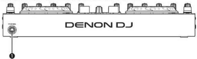
① Headphone jack (PHONES)....(10)
Rear panel
For buttons not explained here, see the page indicated in parentheses ().

① Theft protection lock hole
Connect to an anti-theft wire
② AC adapter cord holder....(4)
This prevents the AC adapter plug from disconnecting.
Use a Phillips screwdriver to anchor the AC adapter cable to this holder.
③ DC IN jack (DC IN) ...... (4)
4 Power switch (POWER) ..... (10)
NOTE
There is no function on this device for automatically switching off the power supply when the unit is not used for a prolonged period.
If you do not intend to use this device for a prolonged period, for safety either switch off the power supply, or remove the AC adaptor plug from the wall socket.
⑤ USB terminal (USB) .....(4)
⑥ Master output terminal
(MASTER OUT BALANCED)....(3)
⑦ Master output terminal
(MASTER OUT UNBALANCED)……(3)
⑧ Line 1/2 input terminal
(LINE 1/2) ...... [3]
⑨ Balanced microphone input terminal (MIC) 13
Troubleshooting
If a problem should arise, first check the following:
-
Are the connections correct?
-
Is the set being operated as described in this owner's manual?
-
Is the external device (player or effects processor) operating correctly?
If this unit does not operate properly, check the items listed in the table below.
If the symptom is not covered on the check list, contact your dealer or service centers.
Service centers are listed at http://www.o-mpro.com or http://www.dencdj.com.
| Symptom Cause/Solution Page | ||
| Power does not turn on. | Check the connection of the power plug to the outlet and the connection of the DC plug to the unit. | 4 |
| There is no sound, or the sound is too quiet. | Check the connections for all devices.The microphone ducking function is operating. Set the DUCKING button to off. | 3, 410 |
| The sound is distorted. | Adjust the master output level adjustment knob.Adjust the channel input level adjustment knob. | 1010 |
| This unit does not operate properly, or there is no sound. | Check the connections for all devices.Check that the volume settings for the connected devices and DJ software on the computer are properly adjusted.Match the settings on the unit to those on DJ software.WAV files become mixed if the sampling frequency and bit number are different. Depending on the audio application used, WAV files that have different sampling frequencies or bit numbers cannot be played simultaneously.When other USB devices are connected to the computer, connect only the unit to the computer and check if this works. | 3, 41012, 13-- |
| Sound cuts out or is distorted. | Exit any other applications.When multiple WAV files are played back simultaneously, the playback sound may cut out depending on the computer specifications. Try playing back 1 WAV file. | -- |
| The button lights are dim. | The dimmer is in operation. Check the dimmer settings on the computer. | - |
Specifications
Audio
(0 dBu=0.775 Vrms, 0 dBV =1 Vrms)
• LINE inputs 2 Stereo
Unbalanced RCA terminal
Input impedance: 51 kΩ
Level: 0 dBV
Signal to Noise ratio: Over 87 dB
• Microphone inputs 1 Monaural
Microphone : Balanced 1/4 in. TRS terminal
(Tip: hot, Ring: cold, Sleeve: ground)
Input impedance: 10 kΩ
Level: -52 - -20 dBu (Unity = -40 dBu)
• USB AUDIO inputs 2 Stereo (4 Monaurall) 16 bit, Fs: 48 kHz USB B
- MASTER output
Balanced: Stereo, balanced 1/4 in. TRS terminal
(Tip: hot, Ring: cold, Sleeve: ground)
Load impedance: Over 600 Ω
Level: +4 dBu (Max +24 dBu)
- When RL = 10 kΩ
Frequency response: 20 Hz - 20 kHz (±0.5 dB)
THD: Less than 0.05 %
Crosstalk: Less than -85 dB (1 kHz)
Unbalanced: Stereo RCA terminal
Load impedance: 10 kΩ
Level: 0 dBu (Max +20 dBu)
• Headphone output Stereo 1/4 in. (1 mm)
Load impedance: 40 Ω
Level: Over 100 mW
• USB AUDIO output 2 Stereo (4 Monaurali) 16 bit, FS: 48 kHz USB B
General
USB MIDI input/output: IN: 1ch, OUT: 1ch MIDI 1.0, USB B
MASTER meter: PPM 7 Point LED -20 - +10 dB, Peak
CH fader: 1 1/4 in. (45 mm) slim type fader
Cross fader: 1 1/4 in. (45 mm) fader
• Power voltage: DC 12 V (the unit)
AC adapter input:
U.S.A. and Canada models: AC 120 V, 60 Hz
European,U.K. and Asia/ AC 230 V, 50 Hz
Pacific models:
AC adapter output: DC 12 V 2 A
Power consumption: 16 W
Operating temperature: +5 °C - +35 °C
Operating humidity: 25% - 85%
Storage temperature: -20°C - 60°C
* For the purpose of improvement, the specifications and design are subject to change without notice.
Index
| A | |
| AC adapter | 4 |
| ASIO driver | 5 |
| Cable | 3 |
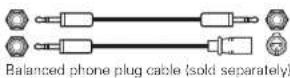
| Balanced phone plug cable | 3 |
| Coaxial cable for microphone | 3 |
| RCA pin plug cable | 3 |
| USB cable | 3 |
| Connection | 3 |
| Balanced main amp | 3 |
| CD player | 3 |
| Coaxial microphone | 3 |
| Computer | 4 |
| Power cord | 4 |
| Unbalanced main amp | 3 |
| D | |
| Ducking | 10 |
| F | |
| Front panel | 29 |
| H | |
| Headphone monitor | 10 |
| J | |
| Jog wheel lock function | 12 |
| ICFL |
| LINE TO MASTER function 11 |
| M | |
| Microphone | 10 |
| MIDI command | 13, 14, 15 |
| MIDI input/output channels | 14 |
| P |
| Power on/off 10 |
| R |
| Rear panel 29 |
| LFT | |
| Top panel | |
| ......18, 19, 20, 21, 22, 23, 24, 25, 26, 27, 28 | |
| Touch sensor......11 | |
| TRAKTOR LE 2......8, 19 |
| USB AUDIO | 12 |
| USB settings | 12 |
| V | |
| Virtual DJ | 9, 24 |
Signal system chart

flowchart
graph TD
    subgraph CH_INPUT
        A["CH INPUT"] --> B["LINE THIND1 L/S"]
        B --> C["INPUT1"]
        C --> D["SW 110A"]
        D --> E["INPUT2"]
        E --> F["SW 110B"]
        F --> G["OUTPUT"]
        G --> H["LEVEL MADS"]
        H --> I["POWER"]
        I --> J["POWER OUT"]
        J --> K["Master OUT -40Hz"]
        K --> L["POWER OUT -40Hz"]
        L --> M["PHONE 300000000000"]
    end

    subgraph MIC_INPUT
        N["MIC INPUT"] --> O["MC MADS"]
        O --> P["MOND"]
        P --> Q["SW 110A"]
        Q --> R["USB AUDIO MASTER"]
        R --> S["SW 110B"]
        S --> T["USB AUDIO OUT"]
        T --> U["USB AUDIO OUT"]
        U --> V["USB AUDIO OUT"]
        V --> W["USB AUDIO OUT"]
        W --> X["USB AUDIO OUT"]
        X --> Y["USB AUDIO OUT"]
    end

    subgraph OUTPUT
        Z["OUTPUT"] --> AA["SW 110A"]
        AA --> AB["BUCKING"]
        AB --> AC["SW 110B"]
        AC --> AD["OUT"]
        AD --> AE["LEVEL MADS"]
        AE --> AF["POWER"]
        AF --> AG["POWER OUT"]
        AG --> AH["Master OUT -40Hz"]
        AH --> AI["PHONE 3000000000000"]
        AI --> AJ["OUTPUT"]
        AJ --> AK["LEVEL MADS"]
        AK --> AL["POWER"]
Dimensions

D&M Holdings Inc.
V00
3520 10061 00AP

- MC3000
- CAUTION
- RISK OF ELECTRIC SHOCK
- DO NOT OPEN
- CAUTION:
- IMPORTANT TO SAFETY
- WARNING:
- FCC INFORMATION (For US customers)
- COMPLIANCE INFORMATION
- Product Name: Professional DJ Controller
- Model Number: MC3000
- IMPORTANT NOTICE: DO NOT MODIFY THIS PRODUCT
- NOTE
- IMPORTANT SAFETY INSTRUCTIONS
- READ BEFORE OPERATING EQUIPMENT
- (English)
- VORSICHT:
- (Deutsch)
- - DECLARATION OF CONFORMITY (English)
- A NOTE ABOUT RECYCLING:
- HINWEIS ZUM RECYCLING:
- Accessories
- NOTE
- About this manual
- Symbols
- □Illustrations
- Main features
- Reliable design
- USB MIDI controller
- USB AUDIO interface
- Others
- Cautions on handling
- • Before turning the power switch on
- - About condensation
- • Cautions on using mobile phones
- - Moving the unit
- - About care
- Connections
- Preparations
- Cables used for connection
- Input terminal connection
- Output terminal connections
- Connecting to a computer
- □Compatible computers
- □Automatic driver installation
- Connecting the power cord
- Installing and setting up supplied software
- Installing the ASIO driver (Windows only)
- Insert the supplied "MC3000 Resource CD-ROM" into the computer.
- Click "Asio Driver Installation".
- The license agreement screen appears. If you agree, select "I Agree".
- A screen for verifying the folder in which the ASIO driver is to be installed appears.
- Uninstalling
- Starting up
- ① Devices (Device list)
- • ASIO device status
- ② Enable/Disable
- Audio Buffer Size
- ④ OK/Cancel
- OK:
- Cancel:
- ⑤ Bit Resolution
- Sampling Rate
- ⑦ Device Description
- Installing TRAKTOR LE 2
- Installation onto a Mac computer
- Installation onto a Windows computer
- Installing Virtual DJ LE
- Installation into Mac computers
- The image is too blurry to recognize any text content.
- Installation into Windows computer
- 1
- Basic operation
- Turning the power on
- Turning the power off
- Adjusting the volume of the master level
- Microphone input
- Adjusting the microphone input level
- □Enabling the ducking function
- Headphone monitor
- LINE TO MASTER function
- [Example]
- Adjusting the level balance of lines 1/2
- Adjusting the volume of lines 1/2
- Adjusting the sensitivity of the touch sensor
- Jog wheel lock function
- Locking the jog wheel
- Cancelling the jog wheel lock
- USB settings
- USB AUDIO Input/Output
- MIDI command input/output
- MIDI channel assignment
- Range of CH1, CH5, CH9 and CH13
- Range of CH2, CH6, CH10 and CH14
- Range of CH3, CH7, CH11 and CH15
- Range of CH4, CH8, CH12 and CH16
- Switching MIDI input/output channels
- [Lights CUE]
- □Checking the settings
- Setting the MIDI command transmission interval time
- While pressing BROWSE, RECORD and CF MODE together, press POWER.
- Turn SEL.
- Press SEL.
- Press SHIFT on DECK A or B.
- MIDI command list
- Part names and functions
- Top panel
- ① Audio input/output part
- ① Effects/sample adjustment knob (EFX.1/EFX.2/EFX.3/EFX.4)
- EFX.2/EFX.3/EFX.4
- ② Effects ON/OFF switch button (EFX.1/EFX.2/EFX.3/EFX.4)
- EFX.1:
- EFX.2/EFX.3/EFX.4:
- EFX.1/EFX.2/EFX.3/EFX.4
- (LOOP IN/LOOP OUT)
- ② Mixer control channel selection button (DECK A/C, DECK B/D)
- FX ON/OFF switching button (FX ON 1/2) Assigns the deck to effect slot 1 or 2.
- Channel isolator EQ adjustment knob (HI/MID/LOW)
- Load button (LOAD A/C, LOAD B/D) Loads the file selected using 25 SEL to either DECK A or DECK B.
- Track selection knob (SEL.)
- Turn the track selection knob:
- Press the track selection knob:
- Window switch button (BACK/FWD)
- RECORD window switch button (RECORD)
- EFX window switch button (EFX)
- SAMPLE window switch button (SAMPLE)
- BROWSE window switch button (BROWSE)
- ③ Level meter display switching switch (DECK, MASTER)
- DECK:
- Filter cut off adjustment knob (FILTER)
- Channel cue button (CUE DECK A/B/C/D)
- Channel/master level meter
- ② FX ON/OFF switch button (EFX.1/EFX.2/EFX.3/EFX.4)
- ④ Loop point setting button (LOOP IN/LOOP OUT)
- ⑤ Auto loop and loop size adjustment buttons (AUTO LOOP -/+ )
- ⑥ Hot cue button (CUE1/CUE2/CUE3/CUE4) Selects the cue point registered by turning ⑧ CUE 5 - 8 ON/OFF.
- ⑦ Shift button (SHIFT)
- ⑧ Hot cue switch button and display (CUE 5 - 8)
- ⑨ Deck switch button (DECK CHG.) Selects the deck.
- Key lock button (KEY LOCK) With this ON, the key does not change even if you adjust the tempo during playback.
- ⑯ Pitch bend adjustment buttons (PITCH BEND -/+ )
- ⑰ VINYL switching button (VINYL MODE)
- Channel fader knob
- Crossfader knob
- Channel input level adjustment knob (LEVEL)
- Mixer control channel selection button (DECK A/C, DECK B/D)
- FX ON/OFF switching button (FX ON 1/2)
- ②3 Channel isolator EQ adjustment knob (HI/MID/LOW)
- Load button (LOAD A/C, LOAD B/D)
- BROWSER
- File/search results panel:
- File system/
- SAMPLER: Plays back the samples.
- ② RECORD window switch button (RECORD)
- CF MODE button
- SAMPLE window switch button (SAMPLE)
- BROWSE window switch button (BROWSE)
- ③2 Level meter display switching switch (DECK, MASTER)
- MASTER:
- Filter cut off adjustment knob (FILTER)
- Channel cue button (CUE DECK A/B/C/D)
- Channel/master level meter
- Front panel
- Rear panel
- Troubleshooting
- Specifications
- Audio
- General
- Index
- Dimensions
Brand : DENON
Model : MC3000
Category : DJ Equipment