HKTS 65 - Speaker HARMAN KARDON - Free user manual and instructions
Find the device manual for free HKTS 65 HARMAN KARDON in PDF.

User questions about HKTS 65 HARMAN KARDON
0 question about this device. Answer the ones you know or ask your own.
Ask a new question about this device
Download the instructions for your Speaker in PDF format for free! Find your manual HKTS 65 - HARMAN KARDON and take your electronic device back in hand. On this page are published all the documents necessary for the use of your device. HKTS 65 by HARMAN KARDON.
USER MANUAL HKTS 65 HARMAN KARDON
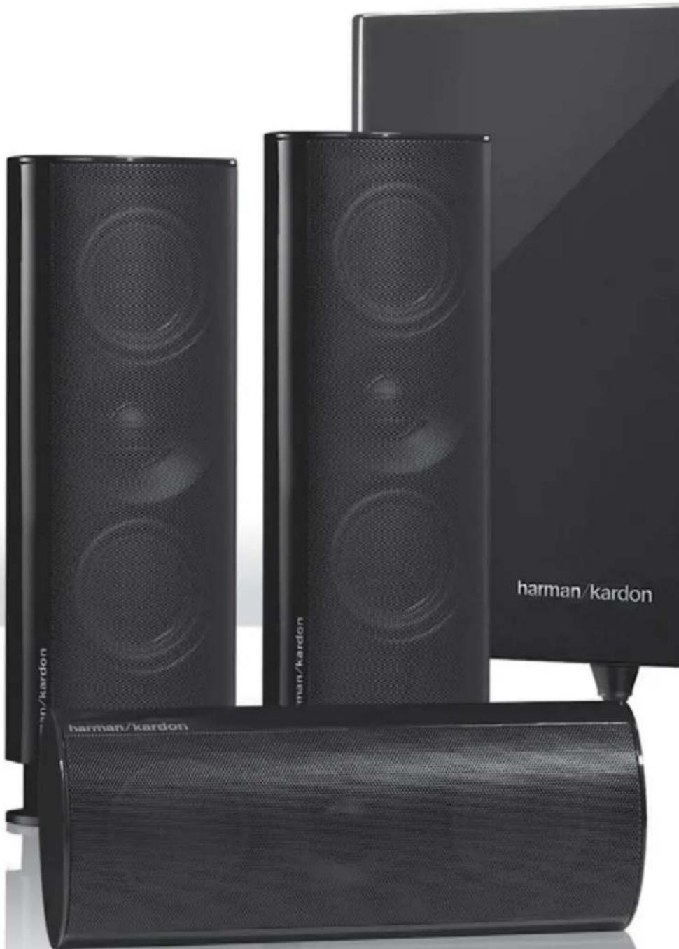
natural_image
Black hardcover kardon speakers with various speaker towers and a compact base (no visible text or symbols on the devices themselves)harman/kardon®
by HARMAN
Introduction
Thank you for purchasing the Harman Kardon® HKTS 65 speaker system, with which you're about to begin many years of listening enjoyment. The HKTS 65 has been custom designed to provide all the excitement and power of the cinema experience in your own living room.
While sophisticated electronics and state-of-the-art speaker components are hard at work within the HKTS 65, hookup and operation are easy, thanks to simple controls and color-keyed cables and connections.
To obtain maximum enjoyment from your new home theater speaker system, we urge you to take a few minutes to read through this manual. It will help ensure that the connections you make to your receiver (or preamp/processor), amplifier and other devices are correct. In addition, a few minutes spent learning the functions of the various controls will enable you to take advantage of all the power and refinement the HKTS 65 is able to deliver.
If you have any questions about this product, its installation or its operation, please contact your dealer. He or she is your best local source of information.
Description and Features
The HKTS 65 is a complete six-piece home theater speaker system that includes:
- A 200-watt wireless powered subwoofer with an 8-inch (200mm) low-frequency transducer
- Four identical, two-way, video-shielded, dual flat-panel midrange satellite speakers for the front left and right, and surround left and right speaker positions
- A dedicated, voice-matched, video-shielded, dual flat-panel midrange center speaker
- Removable bases for the satellite speakers and wall-mount brackets for the satellite and center speakers
- All of the cables you need to connect all of the speakers to your receiver or preamp/processor and amplifier
The speaker cables all use a color-coding system to conform to the Consumer Electronics Association (CEA®) standard. This color-coding system minimizes confusion when connecting the speakers, especially when you are connecting them to a Harman Kardon receiver.
We have equipped the HKTS 220SUB wireless subwoofer and transmitter with Wireless Code switches that allow the subwoofer to avoid interference from other wireless devices while it's operating wirelessly. Other conveniences include a level control, a phase switch for fine-tuning bass response to suit your listening environment and taste, and an efficient switching system that senses the presence of an audio signal and automatically switches the subwoofer from standby mode to on.
We have included wall-mount brackets for the satellite and center speakers and shelf stands for the satellite speakers. Optional HKFS 3 floor stands are available separately from your Harman Kardon dealer.
Harman Kardon engineers invented the high-fidelity receiver over fifty years ago. With state-of-the-art features and time honored circuit designs, the HKTS 65 is a perfect complement to a Harman Kardon receiver or any home theater system.
Included Items

SAT-TS60 Satellite speakers x 4

Satellite wall-mount bracket x 4

CEN-TS60 Center speaker x 1

Center speaker wall-mount bracket x 1

natural_image
Simple line drawing of a rectangular box with three legs and a small label 'Serman Rander' at the bottom (no other text or symbols)HKTS 220SUB wireless subwoofer x 1

Bracket stop plate x 4

Subwoofer wireless transmitter x 1
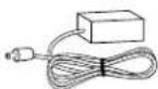
Wireless transmitter power supply x 1
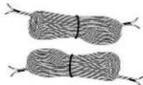
32.8-foot (10m) speaker cables x 2

Transmitter power supply AC cord x 1 (varies with region)
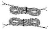
16.5-foot (5m)
speaker cables x 2
Trigger cable x 1

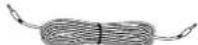
13.1-foot (4m) speaker cable x 1

LFE cable x 1
Subwoofer Rear-Panel Controls and Connections
Subwoofer Unit
text_image
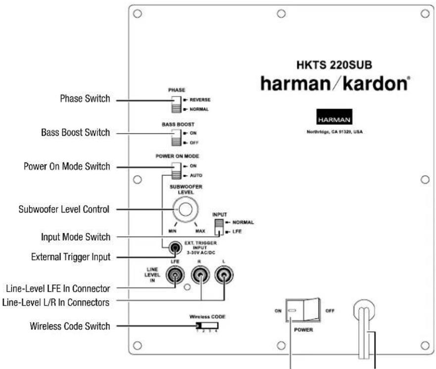
HKTS 220SUB harman/kardon® HARMAN Northbridge, CA 91329, USA Phase Switch PHASE REVERSE NORMAL BASS BOOST ON OFF POWER ON MODE AUTO SUBWOOFER LEVEL MIN MAX INPUT NORMAL LFE Subwoofer Level Control Input Mode Switch EXT. TRIGGER INPUT 3-35V AC/DC External Trigger Input LINE LEVEL IN R L Line-Level LFE In Connector Line-Level L/R In Connectors Wireless Code Switch 2 3 4 ON POWER OFFPower Switch Power Cord
Phase switch: This switch determines whether the subwoofer transducer's piston-like action moves in and out in phase with the satellite speakers. If the subwoofer were to play out of phase with the satellite speakers, the sound waves from the satellites could cancel out some of the subwoofer's sound waves, reducing bass performance and sonic impact. This phenomenon depends in part on the placement of all the speakers in the room. In most cases, the Phase switch should be left in the "Normal" position. However, it does no harm to experiment, and you can leave the Phase switch in the position that maximizes bass response and impact.
Bass Boost switch: Set this switch to "On" to enhance the subwoofer's low-frequency performance. Set this switch to "Off" for normal low-frequency performance.
Power On Mode switch: When this switch is set in the "Auto" position and when the Power switch is set to "On," the subwoofer will automatically turn itself on when it receives an audio signal and will enter the standby mode after it has received no audio signal for about 15 minutes. When this switch is set in the "On" position, the subwoofer will remain on whether or not it is receiving an audio signal. An LED on the subwoofer's top panel indicates whether the subwoofer is in the on or standby state:
- When the LED glows white, the subwoofer is turned on.
- When the LED is not illuminated, the subwoofer is in the standby mode. When the Power switch is set to "Off," the LED will not be illuminated, no matter what setting the Power On Mode switch is in.
Subwoofer Level control: Use this control to adjust the subwoofer's volume. Turn clockwise to increase the volume; turn counterclockwise to decrease the volume.
Input Mode switch: When this switch is in the "Normal" setting, the input signal from the Line-Level L/R In connectors is active. When this switch is in the "LFE" setting, the input signal from the Line-Level LFE In connector is active.
External Trigger Input connector: Use the supplied trigger cable to connect the External Trigger Input connector to the trigger output of another compatible component. Whenever the subwoofer detects a trigger signal between 3V and 30V (AC or DC), its amplifier will turn on. The amplifier will turn off after the trigger signal ceases, even when the Power On Mode switch is in the "Auto" position.
Line-Level LFE In connector: The signal from this connector bypasses the subwoofer's internal low-pass crossover. When you're connecting the subwoofer to the dedicated subwoofer output of a receiver/processor that has its own low-pass crossover network, use the Line-Level LFE In connector. You must also set the subwoofer's Input Mode switch in the "LFE" position.
Line-Level L/R In connectors: The signals from these connectors pass through the subwoofer's internal low-pass crossover. When you're connecting the subwoofer to the preamp or subwoofer outputs of a receiver/processor that does not have its own low-pass crossover network, use both Line-Level L/R In connectors. You must also set the Input Mode switch in the "Normal" position. If your receiver/processor has only one subwoofer output, you can use either the L or R connector.
Wireless Code switch: This switch selects between four different channels for the wireless subwoofer signal.
IMPORTANT: Be sure to set the subwoofer's Wireless Code switch to the same channel that you set the transmitter module's Wireless Code switch. See Wireless Code Settings, on page 10, for more information.
Power switch: Set this switch in the "On" position to turn the subwoofer on. The subwoofer will then be either on or in the standby mode, depending on the setting of the Power On Mode switch.
Power Cord (non-detachable): After you have made and verified all the connections described in this manual, plug this cord into an active, unswitched electrical outlet for proper operation of the subwoofer. DO NOT plug this cord into the accessory outlets found in some audio components.
Transmitter Unit
text_image
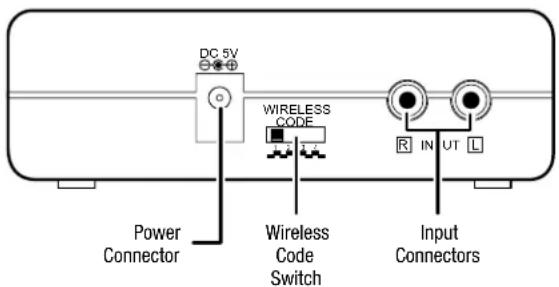
DC 5V WIRELESS CODE Power Connector Wireless Code Switch Input ConnectorsPower connector: Plug the transmitter power supply into this connector and into a working AC outlet.
Wireless Code switch: This switch selects between four different channels for the wireless signal.
IMPORTANT: Be sure to set the transmitter unit's Wireless Code switch to the same channel that you set the subwoofer's Wireless Code switch. See Wireless Code Settings, on page 10, for more information.
Input connectors: Connect the supplied LFE cable from your receiver's or processor's subwoofer output to either of the transmitter unit's Input connectors.
Color-Coding System
The HKTS 65 system uses the channel color-coding system established by the CEA to make setting up your home theater speaker system as easy as possible. The system includes speaker wires and an LFE cable with color bands on each end.
Speaker Position Wire Color Bands
| Front Left White |
| Front Right Red |
| Center Green |
| Surround Left Blue |
| Surround Right Gray |
| Subwoofer Purple |
Speaker Placement
Front speakers
text_image
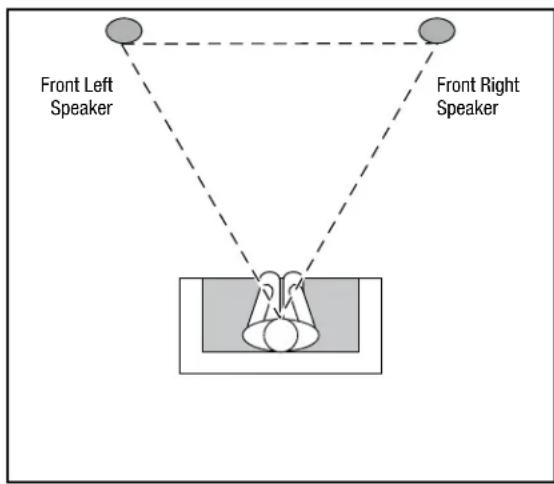
Front Left Speaker Front Right SpeakerPlace the front speakers the same distance from each other as they are from the listener's position. Place them at about the same height from the floor as the listener's ears will be. Angling them towards the listener can improve the stereo imaging.
Center Speaker

text_image
Center Speaker Front Left Speaker 0 - 2 ft (0 - 61cm) Front Right SpeakerPlace the center speaker directly above or below the center of your TV screen. Its center should be no more than two feet (61cm) above or below the centers of the front left and front right speakers. If your TV set is deep enough, it may be convenient to set the center speaker on top of the television set.
Surround Speakers
text_image
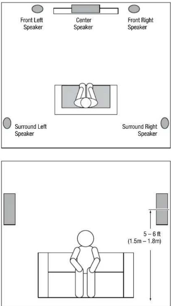
Front Left Speaker Center Speaker Front Right Speaker Surround Left Speaker Surround Right Speaker 5 - 6 ft (1.5m - 1.8m)The two surround speakers should be placed slightly behind the listening position, facing each other, and, ideally should be 5 – 6 feet (1.5m – 1.8m) from the floor. An alternate location would be on a wall behind the listening position, facing forward. The surround speakers should not call attention to themselves while they're playing. Experiment with their placement until you hear a diffuse, ambient sound accompanying the program material heard from the front left, front right and center speakers.
Subwoofer
text_image
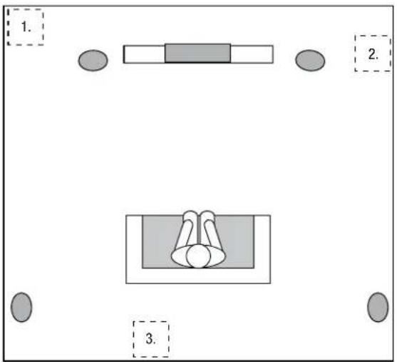
1. 2. 3.The performance of a subwoofer is directly related to its placement in the listening room and its physical position relative to the other speakers in the system. While it is true that in general our ears do not hear directional sounds at the low frequencies where subwoofers operate, when installing a subwoofer within the limited confines of a room, the reflections, standing waves and absorptions generated within the room will strongly influence the performance of any subwoofer system. As a result, the specific location of the subwoofer in the room does become important to the amount and quality of bass that is produced.
For example, placing the subwoofer next to a wall generally will increase the amount of bass in the room; placing it in a corner (1) generally will maximize amount of bass in the room. However, corner placement can also increase the destructive effect of standing waves on bass performance. This effect can vary depending on the listening position – some listening positions may yield very good results while others may have far too much (or too little) bass at certain frequencies.
In many rooms, placing the subwoofer along the same plane as the left and right speakers (2) can produce the best integration between the sound of the subwoofer and that of the left and right speakers. In some rooms, the best performance could even result from placing the subwoofer behind the listening position (3).
We strongly recommend that you experiment with placement before choosing a final location for your subwoofer. One way you can determine the best location for the subwoofer is by temporarily placing it in the listening position and playing music with strong bass content. Move around to various locations in the room while the system is playing (putting your ears where the subwoofer would be placed), and listen until you find the location where the bass performance is best. Place the subwoofer in that location.
Speaker Mounting Options
Shelf Placement
You can place the satellite and center speakers on shelves. The satellite speakers have built-in bases for shelf placement. You can also remove the bases.
To remove a satellite speaker's base, pull it straight off the speaker. Pulling evenly on both sides of the base will allow it to slide off smoothly.
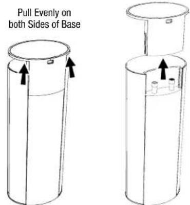
text_image
Pull Evenly on both Sides of BaseWall-Mounting: Satellite Speakers
IMPORTANT: Read the Connections section, on page 8, before wall-mounting the satellite speakers. During the process of installing the brackets you will need to insert the speaker wires through the wall-mount brackets and connect the wires to the speakers.
NOTE: If you are using your own speaker wire, it must be no thicker than the wire supplied with the speakers. Thicker wire will prevent the bracket from sliding onto the speaker.
- Determine the location for the speaker.
- Remove the speaker's base as explained in Shelf Placement, above.
- Slide the two sections of the wall-mount bracket apart.
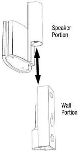
text_image
Speaker Portion Wall Portion- Attach the wall portion of the wall-mount bracket onto the wall using hardware that is appropriate for the wall's construction and materials. We recommend first anchoring the bracket using its keyhole, then attaching it with another anchor through its top opening, as shown in the illustration. Note that the satellite speakers weigh 3.4 lb (1.55kg). Be sure to use hardware that can support this weight.

text_image
Top Opening Keyhole Opening Bottom OpeningNOTE: If you're running the speaker wire through the wall, you can bring it out directly behind the bracket location and insert it through the bottom opening in the wall portion of the bracket. Running the wire in this way will keep the wire completely hidden from view once the installation is complete.

text_image
Insert Wire into Bottom Opening Bring Wire out Through Here- If you're not running the speaker wire through the wall, insert it through bottom of the wall portion of the bracket as shown below.
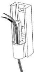
- Pass the speaker wire through the speaker portion of the wall-mount bracket, as shown in the illustration.
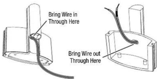
text_image
Bring Wire in Through Here Bring Wire out Through Here- If you have not already removed the speaker's base, do so by pulling it straight off the speaker, as shown in Shelf Placement, above.
CAUTION: Before making speaker connections, be sure that your receiver or amplifier is turned OFF and its AC cord is unplugged from the AC outlet.
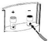
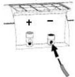
- Connect the speaker wire to the speaker terminals as shown in the illustration:
A) Push Down on Cap to Open Hole

B) Insert Bare Wire into Open Hole
C) Release Cap to Secure Wire

Insert the conductor with the colored band into the speaker's red (+) terminal, and insert the other conductor into the speaker's black (−) terminal.
IMPORTANT: Make sure the (+) and (−) bare wires do not touch each other or the other terminal. Touching wires can cause a short circuit that can damage your receiver or amplifier.
- Slide the speaker portion of the wall-mount bracket onto the speaker as shown in the illustration. Fit the grooves on the bracket onto the rails in the speaker, and apply even pressure on both sides of the bracket so it slides straight onto the speaker.
Fit Bracket Grooves
Onto Speaker Rails

natural_image
Pure mechanical diagram showing a piston-cranked cylinder with arrows indicating force direction (no text or symbols)Push Down Evenly On
Both Sides of Bracket

- Pull any slack speaker wire back through the bracket as you slide the bracket onto the speaker.
- Push the bracket all the way onto the speaker until it snaps into place.
- Slide the speaker onto the bracket's wall section, as shown in the illustration. Pull any slack speaker wire back through the bracket's wall section.
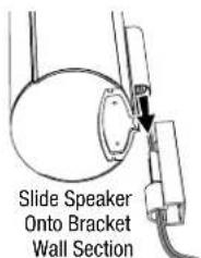
text_image
Slide Speaker Onto Bracket Wall Section
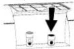
- Fit the metal stop plate into the recess on the bottom of the bracket with the pad facing the bracket, and fasten it to the bracket using two of the supplied screws. It will prevent the speaker from detaching from the bracket and will hold the speaker's position as you rotate it.

natural_image
Diagram showing a mechanical assembly before and after change, with no visible text or symbolsWall-Mounting: Center Speaker
-
Determine the location for the speaker.
-
Attach the center speaker wall-mount bracket to the wall using hardware that is appropriate for the wall's construction and materials. Attach the anchors through the holes shown in the illustration.

text_image
Use These Holes to Attach Bracket to WallNOTE: The center speaker weighs 3.3 lb (1.5kg). Be sure to use hardware that can support this weight.
CAUTION: Before making speaker connections, be sure that your receiver or amplifier is turned OFF and its AC cord is unplugged from the AC power source.
- Connect the speaker wire to the speaker terminals as shown in the illustration:
A) Push Down on Cap to Open Hole
B) Insert Bare Wire into Open Hole
C) Release Cap to Secure Wire

Insert the conductor with the green colored band into the speaker's red (+) terminal, and insert the other conductor into the speaker's black (−) terminal.
IMPORTANT: Make sure the (+) and (−) bare wires do not touch each other or the other terminal. Touching wires can cause a short circuit that can damage your receiver or amplifier.
- Using two of the supplied screws, attach the center speaker to the bracket, as shown in the illustration.
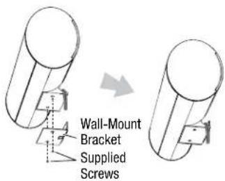
text_image
Wall-Mount Bracket Supplied ScrewsConnections
Satellite and Center Speaker Connections
CAUTION: Before making speaker connections, be sure that your receiver or amplifier is turned OFF and its AC cord is unplugged from the AC power outlet.
Speakers and receivers/amplifiers have corresponding (+) and (−) connection terminals. Most electronics makers use red to denote the (+) terminal and black for the (−) terminal. Newer Harman Kardon receivers conform to the CEA standard and use specific colors to denote the (+) terminals of the speaker positions. See the table in Color-Coding System, on page 4.
Each speaker wire included with your system has colored bands at both ends of the (+) conductor that correspond with the colors defined by the CEA standard. This system helps ensure that the speaker in each location is connected to the correct receiver or amplifier terminals. In addition to the colored bands at each end, each speaker wire's (+) terminal has ribs molded into its insulation to help you identify it.

flowchart
graph TD
    A["Front Left Satellite Speaker"] --> B["White Colored Band"]
    C["Center Speaker"] --> D["Green Colored Band"]
    E["Front Right Satellite Speaker"] --> F["Red Colored Band"]
    G["Receiver/Amplifier"] --> H["Blue Colored Band"]
    I["Surround Left Satellite Speaker"] --> J["Blue Colored Band"]
    K["Surround Right Satellite Speaker"] --> L["Gray Colored Band"]
    B --> H
    D --> H
    F --> H
    H --> J
    H --> L
It is very important to connect each speaker identically: (+) on the speaker to (+) on the receiver or amplifier, and (−) on the speaker to (−) on the receiver or amplifier. Miswiring one or more speakers results in thin sound, weak bass and a poor stereo image. With the advent of multichannel surround-sound systems, connecting all of the speakers in your system correctly is very important to achieving the proper ambience and directionality of surround-sound program material.
Connecting Satellite Speakers without the Supplied Bases
A) Push Down on Cap to Open Hole
B) Insert Bare Wire into Open Hole

C) Release Cap to Secure Wire

Insert the conductor with the colored band into the speaker's red (+) terminal, and insert the other conductor into the speaker's black (−) terminal.
IMPORTANT: Make sure the (+) and (−) bare wires do not touch each other or the other terminal. Touching wires can cause a short circuit that can damage your receiver or amplifier.
Connecting Satellite Speakers with the Supplied Bases
- Remove the speaker's base (see Shelf Placement, on page 5).
- Pass the speaker wire through the opening in the speaker's base.
- Connect the speaker wires as described above.
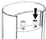
- Reattach the speaker's base, as shown in the illustration.

natural_image
Diagram of a mechanical device with a cylindrical top and two circular base, showing internal components and directional arrows (no text or symbols)Subwoofer: Wireless Connection
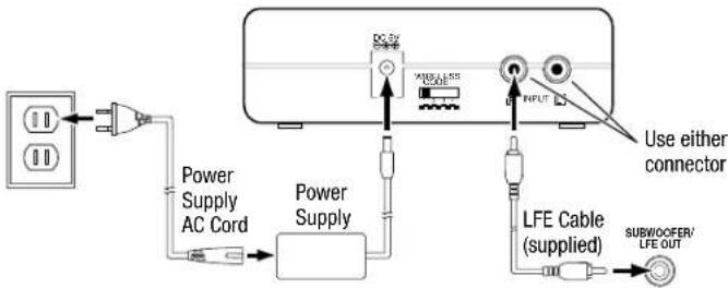
text_image
DC 5V POWER AC Cord Power Supply Power Supply LFE Cable (supplied) USE either connector SUBW/OOFER/ LFE OUT- Connect the supplied LFE cable from your receiver's or processor's subwoofer output to either of the transmitter unit's Input connectors.
- If your receiver/processor does not have a dedicated subwoofer output but does have a set of preamp-level (volume-controlled) line outputs, use a stereo audio cable (not supplied) to connect them to both of the transmitter unit's Input connectors
- Connect the transmitter power supply to the Power connector, and into a working AC outlet,
- Set the Wireless Code switches on the transmitter unit and subwoofer to the same position.
Subwoofer: Wired Connection
As an alternative to wireless operation, you can connect the subwoofer conventionally, using the supplied LFE cable.
NOTE: You can use both the wireless and the wired methods to connect the subwoofer to two different sources. However, if you play both sources at the same time the subwoofer will play bass from them both.
Connecting to a Receiver/Processor with a Dedicated Subwoofer Output
Use this installation method for receivers and preamps/processors that have a dedicated subwoofer output.
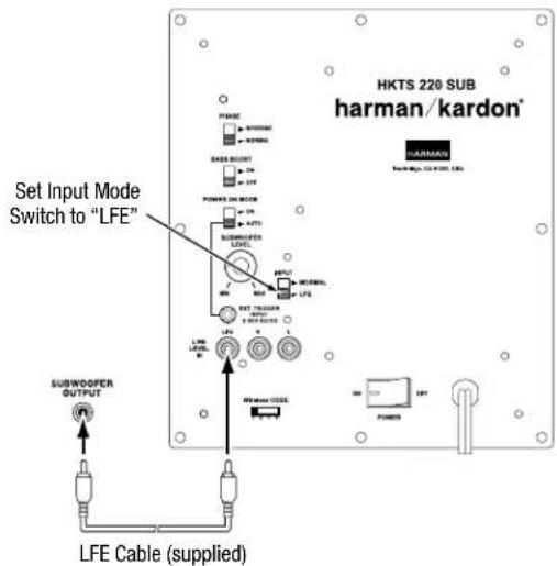
text_image
HKTS 220 SUB harman/kardon® PHASE POWER SABE POINT OFF POMES ON MODE AUTO SUBWOOPER LEVEL OUTPUT MATERIAL LFE SET TRIGGER INPUT 1.5V AC/DC LFE LEVEL B WATER CODE SUBWOOPER OUTPUT OFF LFE Cable (supplied)Use the supplied LFE cable to connect the subwoofer's Line-Level LFE In connector to the dedicated subwoofer output (or LFE output) of your audio/video receiver or preamp/processor. Set the subwoofer's Input Mode switch in the "LFE" position.
Configure your receiver or preamp/processor's setup menu for "Subwoofer On." After you have made and verified all connections, plug the subwoofer's AC Power Cord into a working AC outlet.
Connecting to a Receiver/Amplifier without a Dedicated Subwoofer Output
Use this installation method for receivers and preamp/processors that do not have a dedicated subwoofer output but do have preamp-level (volume-controlled) line outputs. Connect one end of a stereo RCA audio cable (not supplied) to the receiver's or amplifier's stereo line outputs and the other end to the subwoofer's Line-Level L/R In connectors. Set the subwoofer's Input Mode switch in the "Normal" position.
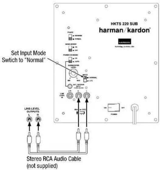
text_image
Set Input Mode Switch to "Normal" Line-LEVEL OUTPUTS L H Stereo RCA Audio Cable (not supplied) PHASE AVGEM NORMAL MIME MACH OFF POWER DO MODE ON OUT RUTS AVGEM NORMAL LUTS UNIT SET VISTAAR OFF RUTS AVGEM LUTS UNIT OFF POWER HKTS 220 SUB harman/kardon® HARMAN SUNTERIOR - 3.100V DCAfter you have made and verified all connections, plug the subwoofer's AC Power Cord into a working AC outlet.
Connecting the Subwoofer to a Trigger Voltage Source
The subwoofer will automatically turn on if it receives a trigger voltage at its External Trigger Input connector and will enter the Standby mode when the voltage ceases.
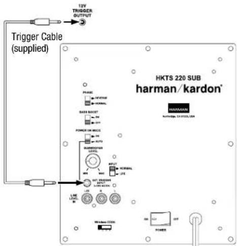
If your preamp/processor or another audio/video component has a trigger-voltage connection that supplies between 3V and 30V (AC or DC), connect it to the subwoofer's External Trigger Input connector. If the component's trigger-voltage connection has a 3.5mm mini jack, you can use the supplied Trigger cable to make the connection.
NOTE: Do not connect the subwoofer's External Trigger input connector to a remote control output (IR Out) of your home cinema system or surround receiver. Doing so could lead to malfunction.
Operating Your Subwoofer
Turning the Subwoofer On and Off
Set the subwoofer's Power switch to the "On" position. If you set the Power On Mode switch to "Auto," the subwoofer will automatically turn itself on when it receives an audio signal, and it will go into the standby mode after it has received no audio signal for 15 minutes. The subwoofer's LED will glow white when the subwoofer is on and will not be illuminated when the subwoofer is in the standby mode.
If you set the Power On Mode switch to "On," the subwoofer will remain on at all times. The subwoofer's LED will glow white.
If you connected the subwoofer's External Trigger Input connector to a trigger-voltage source, the subwoofer will turn on whenever a trigger voltage is present and will enter the standby mode after the trigger voltage ceases, regardless of the position of the Power On Mode switch.
If you will be away from home for an extended period of time, or if you will not be using the subwoofer for an extended period, set the Power switch in the "Off" position.
Wireless Operation
When the wireless transmitter receives an audio signal from the source, it will immediately turn on and its status LED will change to flashing green or solid green:
Green (flashing): Transmitter is on but has not established a link with the wireless subwoofer
Green (solid): Transmitter is on and has already established a link with the wireless subwoofer.
Red: Standby (no signal detected, transmitter off)
The transmitter will automatically enter the Standby mode after no audio signal is detected from the source for approximately 10 minutes.
Wireless Code Settings
The Wireless Code selectors on the transmitter unit and subwoofer must be set to the same position for the system to function correctly.
In the unlikely event that there is interference when operating the system, or if you have more than one HKTS 220SUB operating, you may change the channel at which the system operates. Set the Wireless Code selectors on one subwoofer's transmitter module and subwoofer to one of the other three positions.
You can also set up a maximum of two subwoofers to receive audio from a single transmitter by setting the Wireless Code selectors on the transmitter and both of the subwoofers to the same position.
Subwoofer Adjustments
Volume
Use the Subwoofer Level Control to set the subwoofer's volume. Turn the knob clockwise to increase the subwoofer's volume; turn the knob counterclockwise to decrease the subwoofer's volume.
Notes on Setting Subwoofer Volume:
Sometimes the ideal subwoofer volume setting for music is too loud for films, while the ideal setting for films is too quiet for music. When setting the subwoofer volume, listen to both music and films with strong bass content and find a "middle ground" volume level that works for both.
If your subwoofer always seems too loud or too quiet, you may want to place it in a different location. See Speaker Placement: Subwoofer, on page 5, for more information.
Phase
The Phase switch determines whether the subwoofer's piston-like action moves in and out in phase with the satellite speakers. If the subwoofer were to play out of phase with the satellite speakers, the sound waves from the satellites could cancel out sound waves from the subwoofer, reducing bass performance and sonic impact. This phenomenon depends in part on the placement of all the speakers in the room.
Although in most cases the Phase switch should be left in the "Normal" position, there is no absolutely correct setting for the Phase switch. When the subwoofer is properly in phase with the satellite speakers, the audio will be clearer, have maximum impact and make percussive sounds like drums, piano and plucked strings sound more lifelike. The best way to set the Phase switch is to listen to music that you know well and set the switch in the position that gives drums and other percussive sounds maximum impact.
Bass Boost
When set to the "On" position, the Bass Boost switch enhances low-frequency performance, resulting in bass with more impact, which you may prefer while watching movies or listening to music. There is no harm in experimenting with this control. Setting the switch to the "Off" position will return normal low-frequency performance to your system.
Specifications
HKTS 65 System
| Frequency response: 45Hz – 20kHz (−6dB) |
SAT-TS60 Satellite Speakers
| Midrange transducers: Dual 3" (75mm) honeycomb flat-diaphragm drivers, video-shielded | |
| High-frequency transducer: 1" (25mm) CMMD | ® Lite dome, video-shielded |
| Suggested amplifier power range: 20 – 150 watts | |
| Nominal impedance: 8 ohms | |
| Sensitivity (2.83V/1m): 83dB | |
| Enclosure type: Sealed | |
| Dimensions (H x W x D): | 11-25/32" x 4-11/32" x 3-15/32"(299mm x 110mm x 88mm), including stands |
| Weight: | 3.4 lb (1.55kg) |
CEN-TS60 Center Speaker
| Midrange transducers: Dual 3" (75mm) honeycomb flat-diaphragm drivers, video-shielded | |
| High-frequency transducer: 1" (25mm) CMMD Lite dome, video-shielded | |
| Suggested amplifier power range: 20 – 150 watts | |
| Nominal impedance: 8 ohms | |
| Sensitivity (2.83V/1m): 83dB | |
| Enclosure type: Sealed | |
| Dimensions (H x W x D): | 4-11/32" x 10-11/32" x 3-15/32"(110mm x 272mm x 88mm), including stands |
| Weight: | 3.3 lb (1.5kg) |
HKTS220SUB Wireless Subwoofer
| Low-frequency transducer: | 8" (200mm) down-firing cone |
| Amplifier power: | 200 watts (continuous), 400 watts (peak) |
| Frequency response: | 45Hz – 200Hz (-6dB) |
| Controls: | Volume, phase, bass boost |
| Connections: | LFE (RCA-type); left and right line-level (RCA-type) |
| Enclosure type: | Sealed |
| External trigger input voltage: | 3 – 30 volts, AC or DC |
| Subwoofer power requirement: | 120V, 60Hz (USA); 220V – 240V, 50/60Hz (EU) |
| Subwoofer power consumption: | <0.5W (standby); 243W (maximum, 120V); 261W (maximum, 230V) |
| Subwoofer dimensions (H x W x D): | 13-29/32" x 10-1/2" x 10-1/2" (353mm x 267mm x 267mm) |
| Subwoofer weight: | 19.8 lb (9kg) |
| Transmitter power requirement: | 100 – 240V AC, 50/60Hz |
| Transmitter power consumption: | <0.5W |
| Transmitter unit dimensions (H x W x D): | 1-3/8" x 5" x 3-1/2" (35mm x 127mm x 89mm) |
| Transmitter unit weight: | 0.26 lb (117g) |
Troubleshooting
Your HKTS 65 system is designed for trouble-free operation. Most problems that users encounter are due to operating or connection errors. So if you have a problem, first check this list for a possible solution. If the problem persists, consult your authorized Harman Kardon service center.
Problem Solution
| If there is no sound from any of the speakers: | Check that the receiver/amplifier is on and a source is playing.Make sure that all wires and connections between the receiver/amplifier and the speakers are connected properly.Make sure that the speaker wires are not frayed, cut or punctured.Review the proper operation of your receiver/amplifier. |
| If there is no sound coming from one speaker: | Make sure that all wires and connections between the receiver/amplifier and the speaker are connected properly.Make sure that the speaker wires are not frayed, cut or punctured.Check that the balance control on your receiver/amplifier is not set all the way to one channel.Check your receiver/amplifier's speaker setup procedure to make sure that the speaker in question has been enabled and its volume level has not been turned all the way down. |
| If there is no sound coming from the center speaker: | Make sure that all wires and connections between the receiver/amplifier and the center speaker are connected properly.Make sure that the speaker wires are not frayed, cut or punctured.Check your receiver/amplifier's speaker setup procedure to make sure that the center speaker has been enabled and its volume level has not been turned all the way down.If your receiver is operating in Dolby® Pro Logic® mode, make sure that the center speaker is not set to Phantom. |
| If there is no sound coming from the surround speakers: | Check your receiver/amplifier's speaker setup procedure to make sure that the surround speakers have been enabled and their volume levels have not been turned all the way down.Make sure that all wires and connections between the receiver/amplifier and the surround speakers are connected properly.Make sure the speaker wires are not frayed, cut or punctured.Review proper operation of your receiver/processor and its surround sound features.Make sure the movie or TV show you're watching has been recorded in a surround-sound mode. If it is not, check to see if your receiver/amplifier has a different surround-sound mode that you can use.Review the operation of your DVD player and the DVD jacket to make sure the DVD features the desired Dolby Digital or DTS® surround-sound mode, and that you have properly selected that mode using both the DVD player's menu and the disc's menu. |
| If there is no sound coming from the subwoofer: | Check that the subwoofer's Power cord is plugged into a working AC outlet.Check that the subwoofer's Power switch is in the "On" position.Check that the subwoofer has been properly connected to your receiver/amplifier.Check that the subwoofer's Level control is not turned all the way down.Check your receiver/amplifier's speaker setup procedure to make sure that the subwoofer has been enabled and its volume level has not been turned all the way down.Wireless operation:Check that the transmitter is properly connected to your receiver/amplifier.Make sure that the Wireless Code switches on the transmitter and subwoofer are both set at the same setting. |
| If the system plays at low volumes but shuts off as volume is increased: | Make sure that all wires and connections between the receiver/amplifier and the speakers are connected properly.Make sure none of the speaker wires is frayed, cut or punctured.If you're using more than one pair of main speakers, check to be sure that you're not operating the system below the receiver/amplifier's minimum impedance requirements. |
You can find additional troubleshooting information by clicking on the FAQs link on the Support page at www.harmankardon.com.
natural_image
Black hardcover speakers with sound waves and a modern bar, no visible text or symbols on the devices themselves.HARMAN
HARMAN International Industries, Incorporated
8500 Balboa Boulevard, Northridge, CA 91329 USA
516.255.4545 (USA only)
Made in P.R.C.
© 2012 HARMAN International Industries, Incorporated. All rights reserved.
Harman Kardon and CMMD are trademarks of HARMAN International Industries, Incorporated, registered in the United States and/or other countries. CEA is a registered trademark of the Consumer Electronics Association. Dolby, Pro Logic and the Double-D symbol are registered trademarks of Dolby Laboratories. DTS is a registered trademark of DTS, Inc.
Features, specifications and appearance are subject to change without notice.
Part No. HKP4723 Rev: A
harman/kardon® by HARMAN
www.harmankardon.com