
VB210R - Motorized Ball Valves SCHNEIDER - Free user manual and instructions
Find the device manual for free VB210R SCHNEIDER in PDF.

| Product Type | Ball Valve with Two-Position Actuator (MB6 Series) |
| Model | VB210R |
| Brand | Schneider |
| Power Supply | 24 V AC/DC |
| Actuator Type | Spring return (open or closed depending on model) |
| Control Signal | Two-position (on/off) |
| Flow Configurations | Two-way (A to AB) or Three-way mixing (A to AB and B to AB) |
| Manual Override | Yes, via hex key with max torque 1.3 Nm (10 in/lb) |
| Actuator Removal | Press release lever and lift actuator from valve |
| Mounting Orientation | Horizontal or vertical piping; actuator above valve body for horizontal |
| Pipe Connection | Threaded (male pipe thread, PTFE tape recommended) |
| Ambient Conditions | Avoid excessive moisture, corrosive fumes, explosive vapors, vibration |
| Agency Listings | EMC Directive 2004/108/EC, Low Voltage Directive 72/23/EEC |
| Maintenance | No routine maintenance required; valve stem and packing are maintenance-free |
| Field Repair | Not repairable; replace entire unit if defective |
| Transformer Requirement | One spring return actuator per 10 VA transformer, Class 2 recommended |
| Electrical Terminals | 24H (terminal 2) and 24G (terminal 1) for AC/DC input |
| Wiring | Use 18-24 AWG (0.75-0.22 mm²) copper wire |
| Manual Override Caution | Do not use manual operator while power is applied; permanent damage may occur |
| Valve Stem Indicator | Notch on stem indicates ball position (open/closed) |
Frequently Asked Questions - VB210R SCHNEIDER
User questions about VB210R SCHNEIDER
0 question about this device. Answer the ones you know or ask your own.
Ask a new question about this device
Download the instructions for your Motorized Ball Valves in PDF format for free! Find your manual VB210R - SCHNEIDER and take your electronic device back in hand. On this page are published all the documents necessary for the use of your device. VB210R by SCHNEIDER.
USER MANUAL VB210R SCHNEIDER
Ball Valves with MB6 Series Two-Position Actuators
Inspection
Inspect the package for damage. If package is damaged, notify the appropriate carrier immediately. If undamaged, open the package and inspect the device for obvious damage. Return damaged products.
Requirements
Tools (not provided)
• Wrench 1 to 1-5/8" (25 to 40 mm)
- Pipe wrench according to pipe size
- Volt-ohm multimeter
Training — Installer must be a qualified, experienced technician
Other accessories as appropriate
Notice:
- Electrical shock hazard! Disconnect power before installation to prevent electrical shock or equipment damage.
- Make all connections in accordance with the electrical wiring diagram and in accordance with national and local electrical codes. Use copper conductors only.
- All conductors shall be provided with insulation rated for the highest voltage motor and end switch circuits.
- Avoid locations where excessive moisture, corrosive fumes, explosive vapors, or vibration are present.
- Avoid electrical noise interference. Do not install near large conductors, electrical machinery, or welding equipment.
- When making lead connections within the actuator, use caution not to put leads or connectors below the motor.
- The use in systems which have substantial make-up water (open systems) is not recommended. Follow proper water treatment practices and system procedures.
Mounting
The valves can be mounted in horizontal or vertical piping. When installed in horizontal piping, the actuator must be above the valve body. It can be tilted left or right but it must not be tilted below 90° from vertical.

Piping
These valves must be piped according to the water flow directions as below and marked on the valve. Two-Way valve flow should go A to AB. Three-Way valves should only be applied as mixing valves (see diagram).

Installation Notes
- Ensure there is no overhead water source that may drip onto valve actuator.
- In normal service, some condensation may occur on or around the valve. A drip pan may be necessary or the valve body may be insulated.
- Do not cover the actuator or obstruct the manual operator lever.
• Reference product label and Product Datasheet EN-03-000237-xx-EN for additional product specifications.


Parts on bottom of both actuators are identical.
Installing the Valve Body
Apply PTFE tape to the male pipe thread. Hand screw the pipe into the valve, turning it as far as it will go. Use a wrench to fully tighten the valve to the pipe. Do not over tighten or strip the threads.
Installing the Actuator on the Valve Body
- Turn the valve stem so that the slot on the top of the stem is pointing towards the large keyed post. (See image above)
- Insert the hex key into the slot on the top of the actuator. Rotate eight full revolutions. In the last turn, align the indicator notch to the opening in the manual crankshaft. Press the lock button around manual crankshaft to lock in place. Remove and replace hex key in cover slot.
- Align the valve body with the actuator to ensure the stem lines up with the large stem hole and the large keyed post lines up with the post hole on the bottom of the actuator.
- Press the valve and actuator firmly together to lock into place.
- The first time the valve is operated electrically, the manual crankshaft of the actuator will move to the automatic position. The manual crankshaft can be used to allow flushing of the system after installation.
Removing the Actuator
- Press and hold the valve release lever inward, towards the valve.
- Lift the actuator from the valve.
Notice
- Do not use the valve body to manually open the actuator as damage to the valve actuator will result.
Checkout
- Make sure the valve stem rotates freely before and after installing the actuator.
- If the stem does not operate freely it may indicate that the stem was damaged and may require that the valve be replaced.
- After the piping is under pressure, check the valve body and the connections for leaks.
- After the valve and actuator are installed, power the actuator and check the operation by varying the control signal. On spring return models, the valve should return to its normal position when power is removed.
Manual Override
The manual override lever is designed to manually position the actuator to install on the valve or to manually position the valve. Turning the hex key in the manual crankshaft while power is applied or in the opposite direction as shown on the label will cause permanent damage. Use only the hex key provided with a maximum torque of 1.3 Nm (10 in/lb).
Notice
- Do not use the manual operator while power is applied to the actuator. Manual positioning of the actuator while power is applied is NOT recommended.
Theory of Operation
When powered, the actuator moves to the desired position, tensing the spring return system. When power is removed the actuator returns to the normal position.
Maintenance
The ball valve assembly itself requires no maintenance. The stem and packing design eliminates the need for packing adjustment for the life of the valve. However, regular maintenance of the total heating and cooling system is recommended to ensure sustained optimum performance.
Field Repair
Neither valve nor actuator are field repairable. Replace entire unit as necessary.
Power/Failure Action
| Power/Failure Action | Control Signal Spring Return Open Actuator Spring Return Closed Actuator | |
| 2-Position Power On A to AB Closed A to AB Open | ||
| Power Off A to AB Open A to AB Closed | ||
* Two-Way valve operation described. For a Three-Way valve, A to AB operation is the same. B to AB operation is opposite that of A to AB operation.
Wiring
Make all connections according to job wiring diagrams and in compliance with local and national electrical codes. Refer to diagrams below for typical wiring.
Notice
- Multiple actuators may be connected to a single controller. Do not exceed the maximum current draw of the controller.
- Use only one spring return actuator per 10 VA transformer.
- Use of a properly sized, inherently limited, Class 2 transformer is recommended.
- Use only 18 to 24 AWG (0.75-0.22 mm2) copper wire for all connectors.
- Do not overnighten cover screws.
Wiring Terminals
| Board Marking | Terminal Marking | AC Input DC | Input |
| 24 H 2 24v + | |||
| 24G 1 24v - |

Application Drawing

flowchart
graph TD
    A["Top Coil"] -->|A| B["A"]
    B -->|B| C["Return"]
    C --> D["Bottom Coil"]
    D -->|AB| E["A"]
    E -->|Bypass| F["Return"]
    F --> G["Supply"]
    style A fill:#f9f,stroke:#333
    style D fill:#f9f,stroke:#333
    style E fill:#f9f,stroke:#333
    style F fill:#f9f,stroke:#333
    subgraph Typical Two-Way Fan Coil Application
        A
        B
        E
    end
    style Typical Three-Way Fan Coil Application fill:#ccf,stroke:#333
Note: Typical applications. For simplicity, balancing valves and control devices not shown.
Dimensions


An additional 25 mm is required to remove the actuator from the valve.
Flow Direction
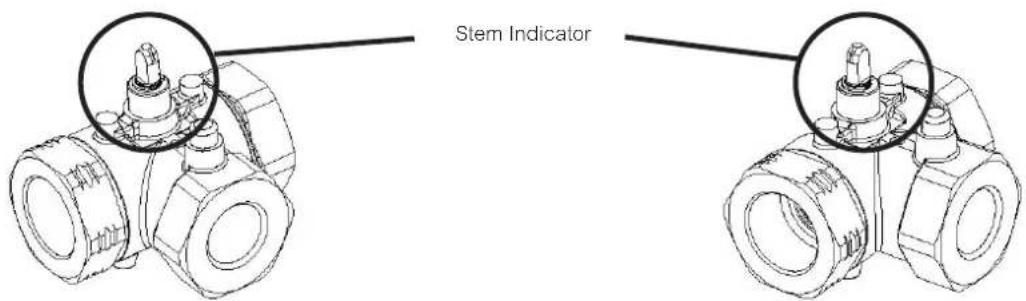
A notch is cut into the tip of the valve stem and is an external indicator for the closed portion of the ball within the valve.
The drawings below mark indicate the stem notch position and ball valve flow path
Notched Stem

Two-Way Open

Notched Stem


Two-Way Closed
Notched Stem

Three-Way, A-Port Open, B-Port Closed
Notched Stem


Three-Way, A-Port Closed, B-Port Open
Agency Listings
European Community: EMC Directive (2004/108/EC). Low Voltage Directive (72/23/EEC).
Brand : SCHNEIDER
Model : VB210R
Category : Motorized Ball Valves