
PT4700S-TMW - Teleprompter Ikan - Free user manual and instructions
Find the device manual for free PT4700S-TMW Ikan in PDF.

| Product Type | Broadcast Teleprompter System |
| Model | PT4700S-TMW |
| Beam Splitter Screen Size | 17" |
| Talent Monitor Screen Size | 19" widescreen |
| Talent Monitor Resolution | 1920x1080 (Full HD) |
| Monitor Inputs | 3G-SDI, HDMI, VGA |
| Monitor Outputs | 3G-SDI loop out (not specified, but likely) |
| Power Input | 12-24V DC |
| Included Software | PrompterPro |
| Maximum Camera Payload (with teleprompter) | 36.5 lbs (16.6 kg) |
| Maximum Camera Payload (without teleprompter) | 56.8 lbs (25.8 kg) |
| Counterweight Included | 2 x 2.5 lbs (total 5 lbs) |
| Pedestal Model | EP880S |
| Pedestal Height Range | 86 cm to 165 cm (33.9 in to 65 in) |
| Pedestal Payload Capacity | 66.1 lbs (30 kg) |
| Dolly Model | EI-7007 Super Dolly |
| Dolly Caster Diameter | 125 mm (4.9 in) |
| Dolly Load Capacity | 220 lbs (100 kg) |
| Fluid Head Model | GH25 |
| Fluid Head Payload Range | 6.6 to 61.7 lbs (3.0 to 28.0 kg) |
| Pan/Tilt Drag Grades | 0-7 (pan and tilt) |
| Counterbalance Steps | 1-15 |
| Warranty | 1 year |
| Included Cases | Custom foam case for teleprompter, separate case for pedestal, bag for dolly |
Frequently Asked Questions - PT4700S-TMW Ikan
User questions about PT4700S-TMW Ikan
0 question about this device. Answer the ones you know or ask your own.
Ask a new question about this device
Download the instructions for your Teleprompter in PDF format for free! Find your manual PT4700S-TMW - Ikan and take your electronic device back in hand. On this page are published all the documents necessary for the use of your device. PT4700S-TMW by Ikan.
USER MANUAL PT4700S-TMW Ikan
natural_image
Exterior view of a professional video camera setup with tripod-mounted monitor, case case, and side-mounted stand (no visible text or symbols)OVERVIEW
Ikan's Turnkey Broadcast Solutions include everything you need for your professional camera setup. This solution includes a 17" teleprompter, pedestal, and dolly. All of our systems have been tested internally for payload compatibility.
The remaining payload capacity, after mounting the full 17" teleprompter without the counterweight, can accommodate camera setups up to 36.5 lbs. The pedestal, without the teleprompter system, can accommodate cameras up to 56.8 lbs. This solution includes a hard case that features custom-cut foam for the entire teleprompter system. This bundle also includes a separate hard case for the pedestal, and a carrying bag for the dolly.

PT4700S-TMW
17" Professional High Bright Beam Splitter Teleprompter w/ 19" Widescreen Talent Monitor (3G-SDI)
What's Included
□ 1 x Teleprompter Base
□ 1 x Bracket with Glass
□ 1 x Teleprompter Hood with Boot
□ 1 x Monitor
□ 1 x AC Adapters with Cord
□ 1 x PrompterPro Software
□ 1 x Counterweight Set (2 x 2.5 lbs)
□ 2 x D-Ring 1/4-20" Screws
□ 2 x Hex Keys
□ 3 x Height Risers
□ 1 x 19" Widescreen Talent Monitor
Teleprompter Assembly Setup
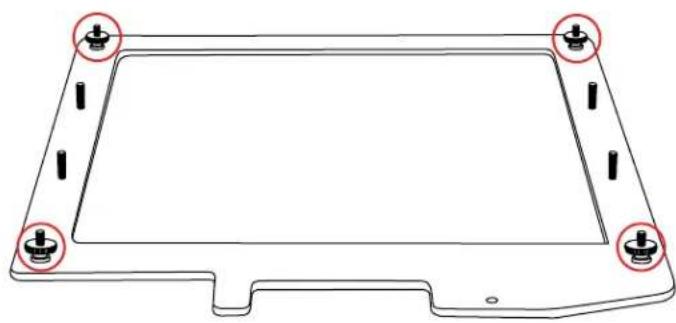
Step 1
Place the teleprompter glass frame on a flat surface and remove the four screws as shown.
natural_image
Technical line drawing of a rectangular electronic component with mounting holes and mounting points (no text or symbols)Step 3
The metal frame is directional. Make sure the thicker side is on top and the slimmer side is on the bottom.

natural_image
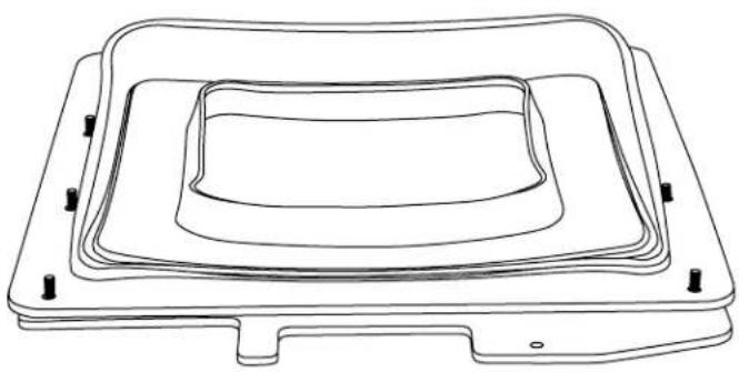
Technical line drawing of a mechanical component with layered internal structure and mounting holes (no text or symbols)Step 2
Align and attach the teleprompter hood with the 8 screw pegs from the teleprompter frame.
natural_image
Line drawing of a rectangular electronic component with concentric layers and mounting holes (no text or symbols)Step 4
Put the washers on before tightening the screws. The washers and 4 additional screws are inside a bag on the bottom foam.

natural_image
Technical line drawing of a mechanical housing or enclosure with mounting holes and internal layered structure (no text or symbols)Step 5
Extend the teleprompter hood open and attach teleprompter boot using the clips. It is suggested to align the seam with the bottom of the teleprompter hood.

natural_image
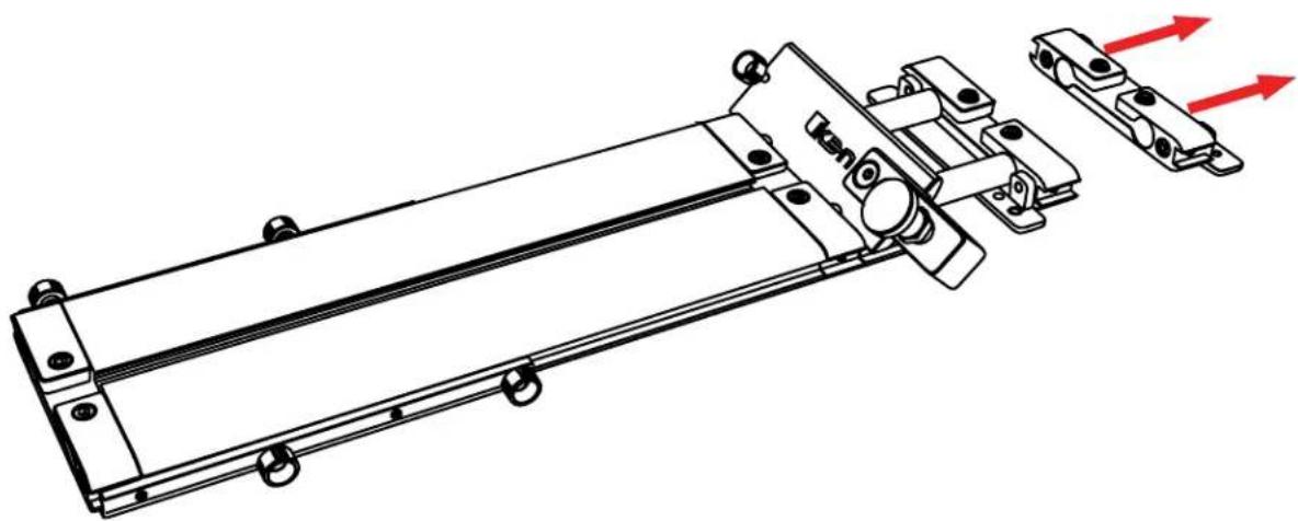
Line drawing of a mechanical device with a dome-shaped component and mounting base (no text or symbols)Step 6
Remove the monitor mounts from the teleprompter base using the included larger 4mm hex key to loosen from the 15mm rods.
natural_image
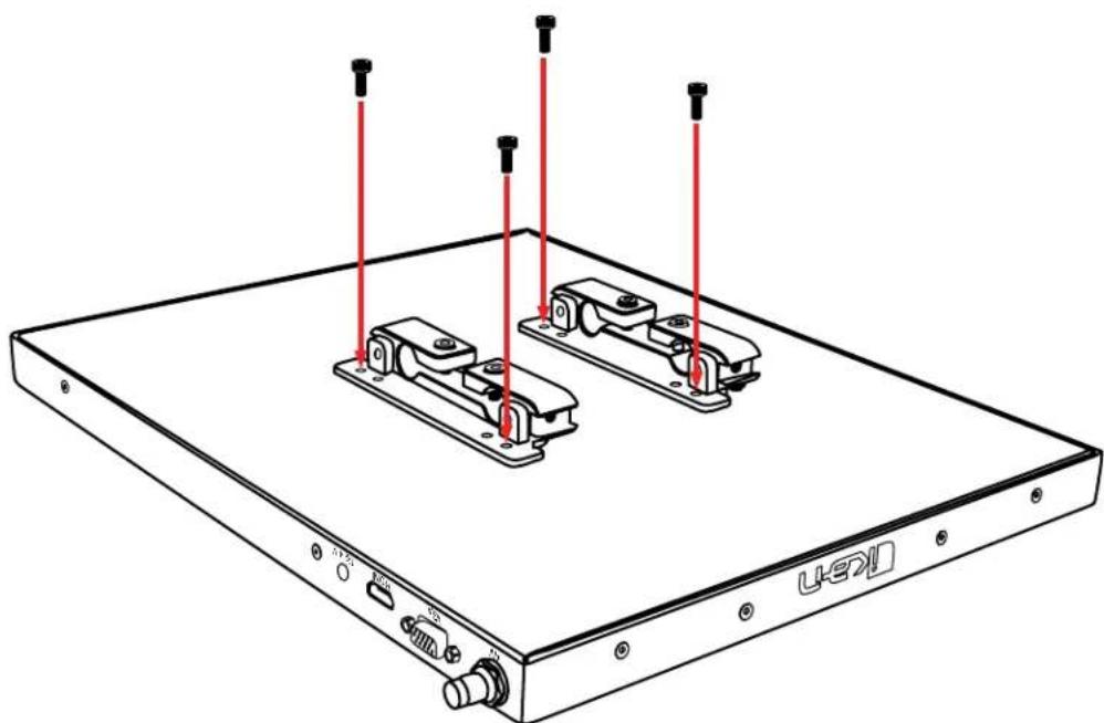
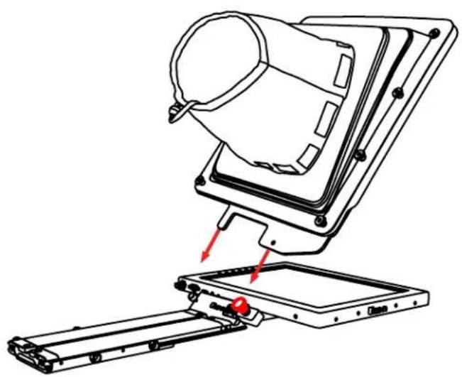
Technical line drawing of a mechanical assembly with red directional arrows indicating motion or force (no text or symbols present)Step 7
Attach the monitor mounts on the back of the monitor's VESA compatible threads using the 4 included screws and provided 2mm hex key.
natural_image
Technical line drawing of a device chassis with mounting brackets and red vertical rods (no text or symbols)Step 8
After the monitor mounts are attached, adjust the 15mm rods to accommodate the monitor. Leave about 1 inch of room for the teleprompter bracket. Make sure the 15mm rods go through both set of monitor mounts. Please ensure that all screws are properly tightened after inserting the monitor. *SAFETY NOTE* Make sure to leave at least 2 inches of the rods inside the teleprompter base.

Step 9
While sliding the teleprompter bracket into the slot of the teleprompter base pull on the red knob to allow the bracket to fully slide in.
Step 10
Once the bracket is in place, tighten the side screw to lock in place. Double check and make sure all the screws are tightened with the included hex keys.
natural_image
Technical line drawing of a mechanical assembly with no visible text or symbols
natural_image
Technical line drawing of a mechanical assembly with no visible text or symbolsStep 11 (optional)
Should the teleprompter be too front heavy, you can attach the included counter weight on the back of the teleprompter base.
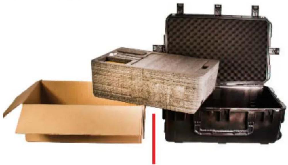
Foam Case
To make your teleprompter more portable, we packed it in a reusable, high-quality foam. The shape and size of the foam was designed to fit into Ikan's PT-CASE-V2.
natural_image
Stacked cardboard and black plastic hard-wear units with open boxes, no visible text or symbols** DO NOT THROW AWAY FOAM CASE **
Monitor Ports
3G-SDI – Serial Digital Interface Connection
VGA – Video Graphics Array DE15 Connection
HDMI – High-Definition Multimedia Interface Input Connection
Power Port - 12-24v Input

HDMI – Switch HDMI input
VGA - Switch to VGA input
SDI - Switch to 3G-SDI input
Flip - Toggle image flip
(Can be set to horizontal, vertical, or both via menu)
Up Arrow – Toggle up to adjust setting
Menu – Access to monitor settings
Down Arrow – Toggle down to adjust setting
Monitor Menu Settings
Video Config
Contrast (White Level)
Brightness (Black Level)
Tint (Chroma Hue)
Chroma (Chroma Saturation)
Sharpness (Detail)
RGB Setup – Manually configure RGB
Return
System Config
Menu Duration – Set duration of how long menu stays on screen
Video Ratio – Set screen aspect ratio 16:9 or 4:3 (4:3 is
native resolution, 16:9 will create black bars)
Flip-H – Assign toggle button to flip image horizontally
Flip-V - Assign toggle button to flip image vertically
Reset - Factory reset
Return
PC Setup (Only available for VGA)
H-Position - Adjust horizontal position
V-Position – Adjust vertical position
Auto – Monitor automatically adjust position Return
Exit
How to set-up FLIP button feature:
- Press MENU button
- Navigate to SYSTEM CONFIG.
- Navigate to FLIP-V or FLIP-H
- Change FLIP-V and/or FLIP-H to "ON"
- Exit MENU
- The FLIP button should now be activated and can be pressed to mirror the image Horizontally or Vertically
- When FLIP-H is ON, the image will flip Horizontally
- When FLIP-V is ON, the image will flip Vertically
- If both are ON, the FLIP button will toggle both Horizontal and Vertical flip
Watch our VIDEO TUTORIAL on how to assemble Ikan Professional Telepromopters:
https://youtu.be/5TjlxzBc_Vc

Optional Accessories
PT4500-G
Replacement Glass for both PT4500-SDI / PT4700-SDI
PT-CASE-V2
Rolling Hard Case for PT4500-SDI / PT4700-SDI Teleprompter
Learn More
More dynamic information at official website: www.ikancorp.com
Support
Contact email: support@ikancorp.com
CONDITIONS OF WARRANTY SERVICE
- Free service for one year from the day of purchase if the problem is caused by manufacturing errors.
- The components and maintenance service fee will be charged if the warranty period is expired.
Free Service will not be Provided in the Following Situations:(*Even if the product is still within the warranty period.)
- Damage caused by abuse or misuse, dismantling, or changes to the product not made by the company.
- Damage caused by natural disaster, abnormal voltage, and environmental factors, etc.
©2018 ikan Corporation. All rights reserved
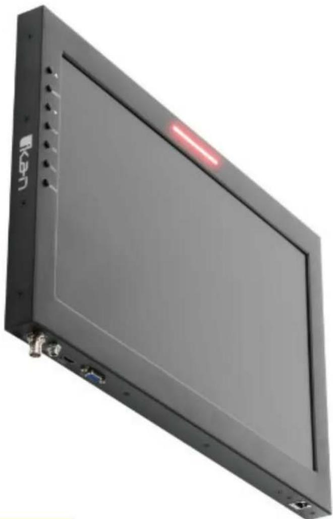
19" High-bright Teleprompter LED ikan Widescreen Monitor w/ Tally
19" SDI Monitor Compatible with Ikan Teleprompters
natural_image
Exterior view of a black rectangular electronic device with a red indicator light on the screen (no visible text or symbols)What's Included
1 x SDI Widescreen Teleprompter Monitor w/ Built-in Tally Light
1 x Power Adapter with Cable
1 x VESA Monitor Mount
1 x 15mm Rod Adapter
1 x Mounting Knob
4 x 10mm Screws
4 x 15mm Screws
2 x Large Screws
4 x Riser Washers
1 x Adjustable Plate
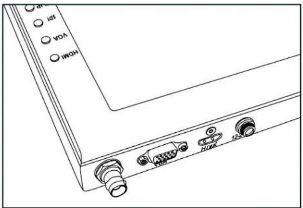
Monitor Ports

3G-SDI – Serial Digital Interface Connection
VGA – Video Graphics Array DE15 Connection
HDMI – High-Definition Multimedia Interface Input Connection
Power Port - 12-24v Input

natural_image
Line drawing of a rectangular TV or analog device with control buttons and a blank screen (no text or symbols on the device itself)HDMI – Switch HDMI input
VGA – Switch to VGA input
SDI – Switch to 3G-SDI input
Flip - Toggle image flip
(Can be set to horizontal, vertical, or both via menu)
Up Arrow – Toggle up to adjust setting
Menu – Access to monitor settings
Down Arrow – Toggle down to adjust setting
Monitor Menu Settings
Video Config
Contrast (White Level)
Brightness (Black Level)
Tint (Chroma Hue)
Chroma (Chroma Saturation)
Sharpness (Detail)
RGB Setup – Manually configure RGB
Return
System Config
Menu Duration – Set duration of how long menu stays on screen
Video Ratio – Set screen aspect ratio 16:9 or 4:3 (4:3 is
native resolution, 16:9 will create black bars)
Flip-H – Assign toggle button to flip image horizontally
Flip-V - Assign toggle button to flip image vertically
Reset - Factory reset
Return
PC Setup (Only available for VGA)
H-Position - Adjust horizontal position
V-Position - Adjust vertical position
Auto - Monitor automatically adjust position
Return
Exit
How to set-up FLIP button feature:
- Press MENU button
- Navigate to SYSTEM CONFIG.
- Navigate to FLIP-V or FLIP-H
- Change FLIP-V and/or FLIP-H to "ON"
- Exit MENU
- The FLIP button should now be activated and can be pressed to mirror the image Horizontally or Vertically
- When FLIP-H is ON, the image will flip Horizontally
- When FLIP-V is ON, the image will flip Vertically
- If both are ON, the FLIP button will toggle both Horizontal and Vertical flip
Supported Video Signals
SDI
720x480i @ 59.94, 60 Hz
720x576i @ 50 Hz
1280x720p @ 50, 60 Hz
1920x1080i @ 50, 59.94, 60 Hz
1920x1080psf @ 24, 25, 29.97, 30 Hz
1920x1080p @ 23.98, 24, 25, 29.97, 30, 50, 59.94, 60 Hz
HDMI
720x480i & 720x480p @ 59.94, 60 Hz
720x576i & 720x576p @ 50 Hz
1280x720p @ 50, 59.94, 60 Hz
1920x1080i @ 50, 59.94, 60 Hz
1920x1080psf @ 24, 25, 29.97, 30 Hz
1920x1080p @ 23.98, 24, 25, 29.97, 30, 50, 59.94, 60 Hz
Assembly Steps
Setting Up the Talent Monitor
Using the shorter 4 x 10mm Screws, attach the VESA Monitor Mount. Make sure that the long end of the VESA Monitor Mount is pointing in the direction of the power button like the image above. Use the Mounting Knob to tighten the 15mm Rod Adapter to the VESA Monitor Mount. Make sure that the top of the VESA Mount is flush with the edge of the monitor.
natural_image
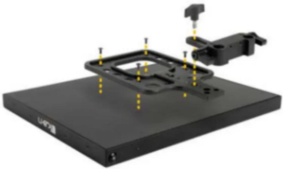
3D rendering of a black electronic device with mounting base and mechanical assembly (no visible text or symbols)Setting Up the Teleprompter Monitor (Script Monitor from the Teleprompter Base System)
If the mounting brackets where previously installed on the teleprompter monitor, remove those screws. Using the longer 4 x 15mm Screws and 4 x Riser Washers attach the mounting brackets with the washers between the bracket and monitor like the image below.
natural_image
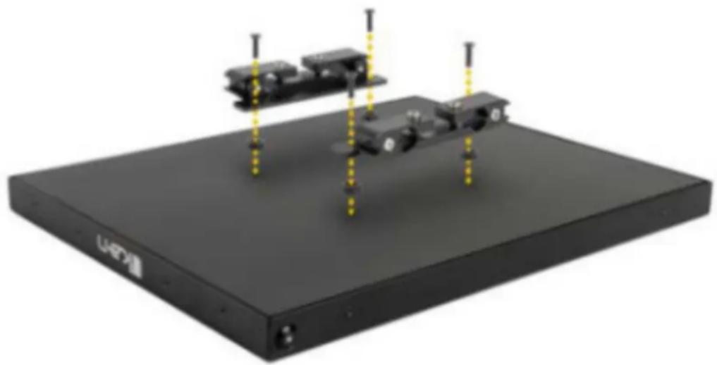
3D rendering of a black electronic device with mounted components and yellow vertical supports (no visible text or symbols)Attaching the Talent Monitor
After both the talent monitor and teleprompter monitor are set up, slide the talent monitor on to the Teleprompter Base System.
*WARNING* We recommend at least 1 inch of rod should be left inside the teleprompter base.

natural_image
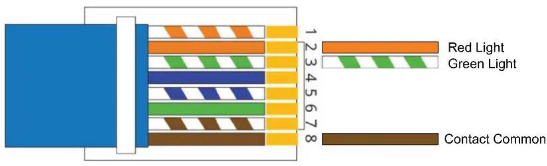
Black rectangular device mounted on a stand with camera module in background (no visible text or symbols)Pinout Diagram for Tally Light
Tally Light Pinout:
Tally Pin Layout Diagram
Learn More
More dynamic information at official website: www.ikancorp.com
Support
Contact email: support@ikancorp.com
CONDITIONS OF WARRANTY SERVICE
- Free service for one year from the day of purchase if the problem is caused by manufacturing errors.
- The components and maintenance service fee will be charged if the warranty period is expired.
Free Service will not be Provided in the Following Situations:(*Even if the product is still within the warranty period.)
- Damage caused by abuse or misuse, dismantling, or changes to the product not made by the company.
- Damage caused by natural disaster, abnormal voltage, and environmental factors, etc.
©2021 Ikan International. All rights reserved.
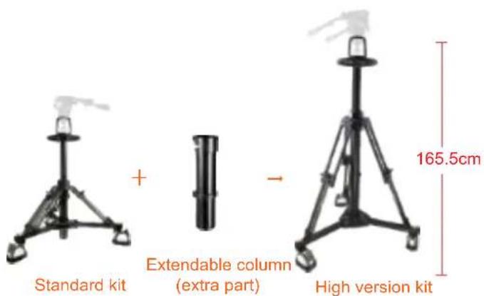
EP880SK
Pedestal

natural_image
Black tripod-mounted camera with mounted sensor and control components (no visible text or symbols)
182.0cm 71.7in

natural_image
Simple tripod-mounted scientific instrument with a flame-like top (no text or symbols visible)Standard kit
-

Extendable column (extra part)
natural_image
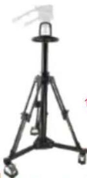
Black tripod-mounted scientific instrument with a small protrusion on top (no visible text or symbols)High version kit
165.5cm

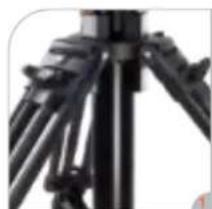
natural_image
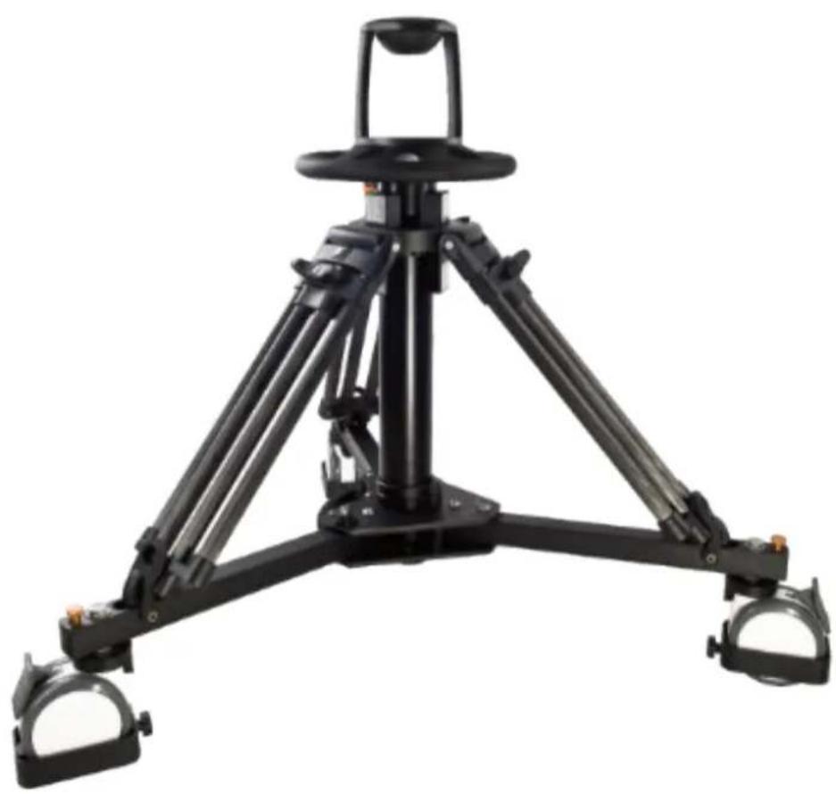
Close-up of a black tripod-mounted camera with tripod legs and tripod arms (no visible text or symbols)Pneumatic column pedestal system
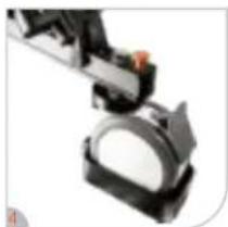
natural_image
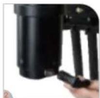
Close-up of a hand holding a black cylindrical device with a handle, no visible text or symbolsAir-pressure in the pneumatic column can be adjusted

natural_image
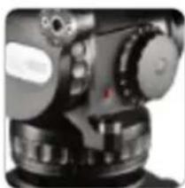
Close-up of a mechanical device with a cylindrical component and a protruding arm (no visible text or symbols)Fluid head with 100mm ball

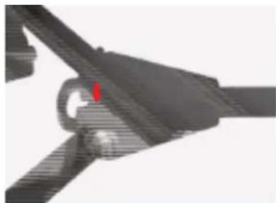
natural_image
Close-up of a mechanical component with a circular base and a handle, no visible text or symbolsDouble-wheel 125mm casters with adjustable cable guards
GH25
100m m FluidHead

natural_image
Close-up of a black industrial camera with mounted components and no visible text or symbols
100mm

3.0-28.0kg
6.6-61.7lbs

1-15
line
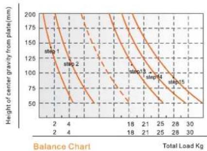
| Total Load Kg | Height of center gravity from plate (mm) | |---|---| | 2 | 200 | | 4 | 175 | | 18 | 150 | | 21 | 125 | | 25 | 100 | | 28 | 75 | | 30 | 50 | Step 1: Step 1 Step 2: Step 2 Step 3: Step 3 Step 4: Step 4 Step 5: Step 5 Step 6: Step 6 Step 7: Step 7 Step 8: Step 8 Step 9: Step 9 Step 10: Step 10 Step 11: Step 11 Step 12: Step 12 Step 13: Step 13 Step 14: Step 14 Step 15: Step 15
FEATURES
natural_image
Close-up of a mechanical surveying instrument (no visible text or symbols)7 plus 0 grades of pan & tilt drag

natural_image
Close-up of a black mechanical knob with circular dial and control knob (no visible text or symbols)15 steps of counterbalance

natural_image
Close-up of a mechanical component with a red dot on top (no visible text or symbols)Illuminated leveling bubble

natural_image
Close-up of a mechanical component with a tool interacting with it (no visible text or symbols)Additional standard 1/4" & 3/8" screw holes
SPECIFICATIONS
| Model | GH25 | |
| Payload Range | 3.0-28.0kg / 6.6-61.7lbs | |
| Counterbalance Range | 1-15 | |
| Grades Of Pan Drag | 0-7 | |
| Grades Of Tilt Drag | 0-7 | |
| Tilt Range | -65irc / +90irc | |
| Temperature Range | -40ircC +80ircC | |
| Bowl Size | 100mm | |
| Net Weight | 4.2kg / 9.2lbs |
EP880S
Pedestal
natural_image
Black tripod-mounted camera with adjustable arms and a flat top (no text or symbols visible)
165.0cm 65.0in

30.0kg 66.1lbs

86.0cm 33.9in

23.9kg 52.7lbs

38.0cm 15.0in

100mm
Component:
| Pedestal | EP880S |
| Dolly | EI7007 |
natural_image
Close-up of a black tripod with tripod legs and adjustable arms (no visible text or symbols)Pneumatic column pedestal system

natural_image
Close-up of a black industrial device with a hand adjusting its part (no visible text or symbols)Air-pressure in the pneumatic column can be adjusted

natural_image
Close-up of a mechanical component with a circular ring and central shaft (no visible text or symbols)Ergonomic hand wheel
natural_image
Close-up of a mechanical assembly with a black component and orange knob (no visible text or symbols)Double-wheel 125mm casters with adjustable cable guards
EI-7007 Super dolly
Designed for pedestal system and other heavy duty system. The 125mm/5inch wheels with cable guard can be individually braked, also the movement direction can be fixed.
Folds for transporting.

FEATURES
natural_image
Close-up of a mechanical component with a red arrow pointing to a circular feature (no visible text or symbols)Pull the knob to extend the dolly, easy to go out.
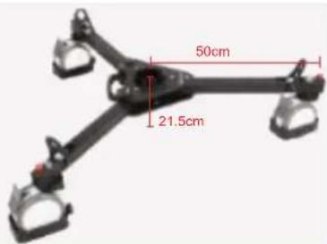
Height : 21.5cm / 8.5in Radius: 50cm / 19.7in

natural_image
Close-up of a mechanical clamp or bracket with a 125mm measurement label (no readable text or symbols beyond the measurement)Casters diameter: 125mm / 4.9in.

The rubber wheels are non-marring during normal use, protecting the oor surface. Each wheel incorporates its own foot-activated brake.

natural_image
Close-up of a mechanical device with red arrows indicating motion or force, no visible text or symbolsCable guards and brakes. Supports up to 100kg of tripod, camera and accessories.

natural_image
3D model of a drone with four wheels and a 100kg payload label (no other text or symbols)GB3 Pan bar
Telescopic pan bar for GH08L, GH10L, GH15, GH25 heads

natural_image
Black and white photo of a black bicycle pushper with textured grip (no text or symbols visible)SPECIFICATIONS
Length range 405-605mm / 15.9-23.8in
Net weight 385g / 0.8lbs


- OVERVIEW
- PT4700S-TMW
- What's Included
- Teleprompter Assembly Setup
- Step 1
- Step 3
- Step 2
- Step 4
- Step 5
- Step 6
- Step 7
- Step 8
- Step 9
- Step 10
- Step 11 (optional)
- Foam Case
- Monitor Ports
- Monitor Menu Settings
- How to set-up FLIP button feature:
- Watch our VIDEO TUTORIAL on how to assemble Ikan Professional Telepromopters:
- Optional Accessories
- Learn More
- Support
- CONDITIONS OF WARRANTY SERVICE
- 19" High-bright Teleprompter LED ikan Widescreen Monitor w/ Tally
- Supported Video Signals
- Assembly Steps
- Setting Up the Talent Monitor
- Setting Up the Teleprompter Monitor (Script Monitor from the Teleprompter Base System)
- Attaching the Talent Monitor
- Pinout Diagram for Tally Light
- EP880SK
- GH25
- FEATURES
- EI-7007 Super dolly
- GB3 Pan bar
- SPECIFICATIONS
Brand : Ikan
Model : PT4700S-TMW
Category : Teleprompter