
MIC2S - Blender Bogen - Free user manual and instructions
Find the device manual for free MIC2S Bogen in PDF.

| Product Type | Microphone Input Module |
| Brand | Bogen |
| Model | MIC2S |
| Input Type | Electronically-balanced, low-impedance |
| Connections | Screw terminal block (+,-,G) |
| Phantom Power | 24V selectable (On/Off) via jumper |
| Gain Control | Adjustable trim |
| Filters | Hi-cut (above 8 kHz) and Lo-cut (below 100 Hz) |
| Voice Enhancer | Adjustable intelligibility enhancement |
| Audio Gating | Adjustable threshold, enable/disable via jumper |
| Limiter | Variable signal limiter |
| Priority Levels | 4 levels (jumper selectable), 1 highest, 4 lowest |
| Muting | Can be muted by higher priority modules; can mute lower priority modules |
| Bus Assignment | A bus, B bus, or both (jumper selectable) |
| Installation | Slides into module bay, secured with two screws |
| Power Requirement | Supplied by host unit (no external power) |
Frequently Asked Questions - MIC2S Bogen
User questions about MIC2S Bogen
0 question about this device. Answer the ones you know or ask your own.
Ask a new question about this device
Download the instructions for your Blender in PDF format for free! Find your manual MIC2S - Bogen and take your electronic device back in hand. On this page are published all the documents necessary for the use of your device. MIC2S by Bogen.
USER MANUAL MIC2S Bogen
MIC2S
Microphone Input Module
Features
• Electronically-balanced
- Screw terminal connections
- Phantom power
- Gain/Trim control
• Hi- and Lo-cut filters
- Adjustable voice enhancer
• Audio gating with threshold adjustment
• Variable signal limiter
• 4 levels of available priority
- Can be muted from higher priority modules
- Can mute lower priority modules
Module Installation
- Turn off all power to the unit.
- Make all necessary jumper selections.
- Position module in front of desired module bay opening, making sure that the module is right-side up.
- Slide module on to card guide rails. Make sure that both the top and bottom guides are engaged.
- Push the module in to the bay until the faceplate contacts the unit's chassis.
- Use the two screws included to secure the module to the unit.
WARNING:
Turn off power to unit and make all jumper selections before installing module in unit.
Jumper Selections
Priority Level\*
This module can respond to 4 different levels of priority. Priority 1 is the highest priority. It mutes modules with lower priorities and is never muted. Priority 2 can be muted by Priority 1 modules and mutes modules set for 3 or 4. Priority 3 is muted by either Priority 1 or 2 modules and mutes Priority 4 modules. Priority 4 modules are muted by all higher priority modules.
* The number of priority levels available is determined by the module capacity of the amplifier the modules are used in.
Gating
Gating can help reduce noise in systems with multiple mic inputs. You can disable gating (turning off) of the module's output when insufficient audio is present at the input. Detection of audio for the purpose of muting lower priority modules is always active regardless of this jumper setting.
Phantom Power
24V phantom power can be supplied to condenser microphones when jumper is set to On position. Leave off for dynamic mics.
Bus Assignment
This module can be set to operate so that the MIC signal can be sent to the main unit's A bus, B bus, or both buses.
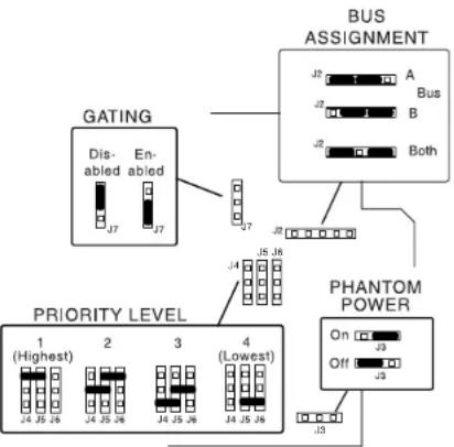
flowchart
graph TD
    A["GATING"] --> B["Dis-abled J7"]
    A --> C["En-abled J7"]
    D["BUS ASSIGNMENT"] --> E["J1 Bus A B Both"]
    D --> F["J2"]
    D --> G["J3"]
    H["PRIORITY LEVEL"] --> I["1 (Highest) J4 J5 J6"]
    H --> J["2 J4 J5 J6"]
    H --> K["3 J4 J5 J6"]
    H --> L["4 (Lowest) J4 J5 J6"]
    M["PHANTOM POWER"] --> N["On Off J3"]
    M --> O["J3"]
Gate
Controls the minimum necessary input signal level to turn the module's output on and apply signal to the main unit's buses. Clockwise rotation increases the necessary signal level required to produce output as well as the signal threshold necessary to cause the module to mute other modules.
Limiter (Limit)
Sets the signal level threshold at which the module will begin to limit the level of its output signal. Clockwise rotation will allow more output signal before limiting, counterclockwise rotation will allow less. The limiter monitors the module's output signal level, so increasing Gain will affect when limiting takes place.
Gain
Provides control over the level of input signal that can be applied to the internal signal buses of the main unit. Allows a way to balance the input levels of various devices so that the main unit controls can be set to relatively uniform or optimum levels.
Enhance
Controls the amount of intelligibility enhancement applied to microphone signal. Intelligibility enhancement provides a crisper sounding signal that is easier to understand over background noise. Clockwise rotation increases the effect.
Hi-Cut
Allows a reduction in the amount of treble frequencies above 8 kHz. This is a cut only filter and does not allow boosting treble. Clockwise rotation increases the amount of cut.
Lo-Cut
Allows a reduction in the amount of bass frequencies below 100 Hz. This is a cut only filter and does not allow boosting bass. Clockwise rotation increases the amount of cut.
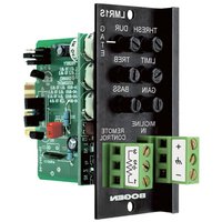
Connections
Uses a screw terminal block to make connections to the module's input. The input is low-impedance, electronically-balanced for excellent noise immunity. Connect signal to + and - terminals and cable shield to G terminal.
Block Diagram
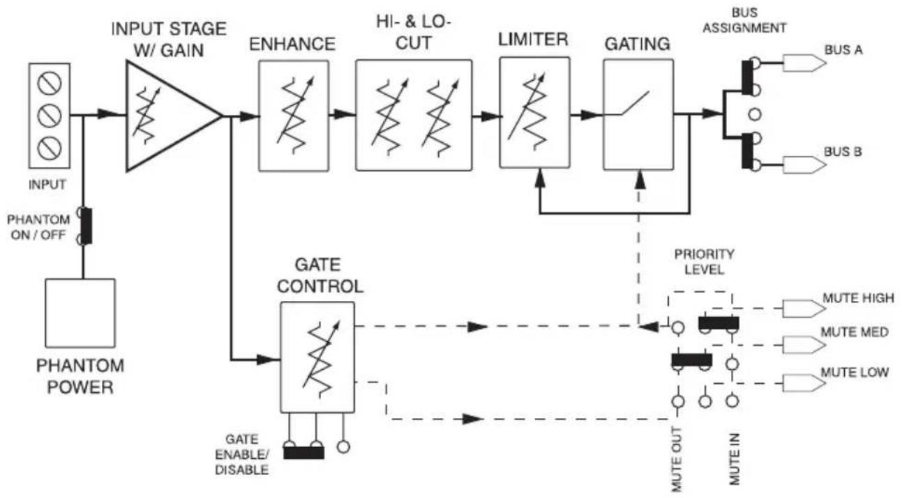
flowchart
graph TD
    A["INPUT"] --> B["PHANTOM ON/OFF"]
    B --> C["PHANTOM POWER"]
    C --> D["INPUT STAGE W/GAIN"]
    D --> E["ENHANCE"]
    E --> F["HI- & LO-CUT"]
    F --> G["LIMITER"]
    G --> H["GATING"]
    H --> I["BUS ASSIGNMENT"]
    I --> J["BUS A"]
    I --> K["BUS B"]
    D --> L["GATE CONTROL"]
    L --> M["GATE ENABLE/DISABLE"]
    M --> N["PRIORITY LEVEL"]
    N --> O["MUTE HIGH"]
    N --> P["MUTE MED"]
    N --> Q["MUTE LOW"]
    O --> R["MUTE OUT"]
    P --> S["MUTE IN"]
    Q --> T["MUTE IN"]


Brand : Bogen
Model : MIC2S
Category : Blender