
XOVV248KSE - Cap XO - Free user manual and instructions
Find the device manual for free XOVV248KSE XO in PDF.


| Product Type | Wall Mount Range Hood |
| Brand | XO |
| Model | XOVV248KSE |
| Width | 48 inches |
| Duct Size | 8" round or 4" x 14" rectangular |
| Mounting Height | Min 16" - Max 31" above cooking surface |
| Controls | Electronic push buttons with indicator lights |
| Speeds | Low, Medium, High, Power Boost (10 min) |
| Timer | 5-minute auto shut-off |
| Lighting | LED, replaceable (type XOPSPK6509) |
| Filters | Anti-grease, dishwasher safe |
| Filter Cleaning | Every 2 months minimum |
| Oil Collector Tray | Removable with 3 knobs |
| Electrical Connection | 120V, 60Hz, grounded |
| Wiring Color Code | Black = Hot, White = Neutral, Green = Ground |
| Optional Remote Control | Model XOVREMOTE1, synchronizable |
| Warranty | 2 years parts and labor |
| Material | Stainless steel |
| Installation Type | Wall mount with decorative chimney |
| Maximum Duct Run | Total equivalent feet less than 100 ft |
| Indoor Use Only | Yes, residential kitchen ventilation |
| Safety Certifications | ANSI/NFPA 70 compliant |
Frequently Asked Questions - XOVV248KSE XO
User questions about XOVV248KSE XO
0 question about this device. Answer the ones you know or ask your own.
Ask a new question about this device
Download the instructions for your Cap in PDF format for free! Find your manual XOVV248KSE - XO and take your electronic device back in hand. On this page are published all the documents necessary for the use of your device. XOVV248KSE by XO.
USER MANUAL XOVV248KSE XO
EVERY THING YOU NEED TO KNOW ABOUT YOUR
X□
XOVV_KSE WALL MOUNT
I worked really hard on this manual - so please read it...
XO

VENTILATION
When buying any XO appliance you can be confident you have chosen a high quality, innovative and stylish product from a company that cares about you!
If you require service or have questions, there are 2 ways to contact our ventilation experts;
Online @ https://xoappliance.com/priority-service-for-your-xo-product/ Or by phone 973-403-8900

CONGRATULATIONS
on purchasing your XO.
Before you proceed, take just a mo-ment to register your XO at:
www.xoappliance.com/register-your-product/
Or simply scan here to be taken to registration page.

Ensuring warranty coverage should you need service Providing ownership verification for insurance purposes Let's XO notify you in the event of product changes or recalls.
WHERE THINGS ARE
GETTING READY 5 - 11
Safety and Precautions
Planning Ductwork
Install Examples
Dimensions
THE INSTALL 12 - 15
Mounting Height
Installing
Electrical Connections
MAINTENANCE 16–18
Filters
Cleaning
Light Replacement
OPERATING 19
The Push Button Controls
PARTS & WARRANTY 20 - 21
PLEASE READ AND FOLLOW ALL SAFETY INSTRUCTIONS
It's for your own good... Honest.
XO
SAFETY FIRST
■ IMPORTANT SAFETY INSTRUCTIONS
■ READ AND SAVE THESE INSTRUCTIONS
■ PLEASE READ ENTIRE INSTRUCTIONS BEFORE PROCEEDING.
■ IMPORTANT: Save these Instructions for the Local Electrical Inspectors use.
■ INSTALLER: Please leave these Instructions with this unit for the owner.
■ OWNER: Please retain these instructions for future reference.
■ Take care when using cleaning agents or detergents.
■ Suitable for use in household cooking area.
■ WARNING - To reduce the risk of fire or electric shock, do not use this fan with any Solid-State Speed Control Device.
■ CAUTION - To reduce risk of fire and to properly exhaust air, be sure to duct air outside – Do not vent exhaust air into spaces within walls or ceilings or into attics, crawl spaces, or garages.
■ CAUTION - For Residential Kitchen ventilating use only. Do not use to exhaust hazardous or explosive materials and vapors.
■ CAUTION - To avoid motor bearing damage and noisy and/or unbalanced impellers, keep drywall spray, construction dust, etc. off power unit.
■ CAUTION - Please read specification label on product for further information and requirements.
■ WARNING – TO REDUCE THE RISK OF FIRE, ELECTRIC SHOCK, OR INJURY TO PERSONS, OBSERVE THE FOLLOWING:
A. Use this unit only in the manner intended by the manufacturer. If you have questions, contact the manufacturer.
B. Before servicing or cleaning unit, switch power off at service panel and lock the service disconnecting means to prevent power from being switched on accidentally. When the service disconnecting means cannot be locked, securely fasten a prominent warning device, such as a tag, to the service panel.
■ WARNING - TO REDUCE THE RISK OF A RANGE TOP GREASE FIRE:
A. Never leave surface units unattended at high settings. Boilovers cause smoking and
greasy spillovers that may ignite. Heat oils slowly on low or medium settings.
B. Always turn hood ON when cooking with high heat.
C. Clean ventilating fans frequently. Grease should not be allowed to accumulate on fan or filter.
D. Use proper pan size. Always use cookware appropriate for the size of the surface element.
E. Keep fan, filters and grease laden surface clean.
F. Use high range setting on range only when necessary. Heat oil slowly on low to medium setting.
G. Don't leave range unattended when cooking.
H. Always use cookware and utensils appropriate for the type and amount off food being prepared.
■ WARNING – TO REDUCE THE RISK OF INJURY TO PERSONS IN THE EVENT OF A RANGE TOP GREASE FIRE, OBSERVE THE FOLLOWING:
A. SMOTHER FLAMES with a close-fitting lid, cookie sheet, or metal tray, then turn off the burner. BE CAREFUL TO PREVENT BURNS. If the flames do not go out immediately, EVACUATE AND CALL THE FIRE DEPARTMENT.
B. NEVER PICK UP A FLAMING PAN – You may be burned.
C. DO NOT USE WATER, including wet dishcloths or towels – a violent steam explosion will result.
D. Use an extinguisher ONLY if:
- You know you have a Class ABC extinguisher, and you already know how to operate it.
- The fire is small and contained in the area where it started.
- The fire department is being called.
- You can fight the fire with your back to an exit.
^a Based on “kitchen firesafety tips” published by NFPA.
Proper maintenance of the Range Hood will assure proper performance of the unit.
■ INSTALLATION INSTRUCTIONS
WARNING – TO REDUCE THE RISK OF FIRE, ELECTRIC SHOCK, OR INJURY TO PERSONS, OBSERVE THE FOLLOWING:
A. Installation work and electrical wiring must be done by qualified person(s) in accordance with all applicable codes and standards, including fire-rated construction.
B. Sufficient air is needed for proper combustion and exhausting of gases through the flue (chimney) of fuel burning equipment to prevent back drafting. Follow the heating equipment manufacturer's guideline and safety standards such as those published by the National Fire Protection Association (NFPA), and the American Society for Heating, Refrigeration and Air Conditioning Engineers (ASHRAE), and the local
code authorities.
C. When cutting or drilling into wall or ceiling, do not damage electrical wiring and other hidden utilities.
D. Ducted fans must always be vented to the outdoors.
E. This unit must be grounded.
■ WARNING - TO REDUCE THE RISK OF FIRE, USE ONLY METAL DUCTWORK.
■ WARNING - UNDER CERTAIN CIRCUMSTANCES DOMESTIC APPLIANCES MAY BE DANGEROUS.
A. Do not check filters with hood working.
B. Do not touch the lamps after a prolonged use of the appliance.
C. No food must be cooked flambè underneath the hood.
D. The use of an unprotected flame is dangerous for the filters and could cause fires.
E. Watch constantly while frying food in order to avoid cooking oil flare ups.
F. Before performing any maintenance operation, disconnect the hood from the electrical service.
■ The manufacturers will not accept any responsibility for possible damages, because of failure to observe the above instructions.
A FEW SIMPLE RULES TO PLAN YOUR DUCTWORK
THIS HOOD IS DESIGNED TO USE AN 8" ROUND DUCT - IT MAY BE TRANSITIONED TO A 4" X 14" RECTANGULAR DUCT
NEVER REDUCE DUCT SIZE. UNDERSIZED DUCTING SEVERELY RESTRICTS AIR FLOW AND HARMS PERFORMANCE.
(Example: the area of an 8" Duct is more than 75% larger than a 6" Duct)
KEEP DUCT RUNS AS SHORT AND STRAIGHT AS POSSIBLE.
AVOID USING FLEXIBLE METAL DUCTING IF RUN IS LONGER THAN 6'.
NEVER USE PLASTIC DUCTING.
USE SMOOTH BORE METAL DUCTING.
MINIMIZE THE NUMBER OF FITTINGS (see chart).
WHEN YOU MUST USE FITTINGS, TRY TO SEPARATE THEM WITH SECTIONS OF 4' OR MORE OF STRAIGHT DUCT.
ALWAYS FOLLOW THE MANUFACTURER'S GUIDELINES FOR THE COOKING EQUIPMENT YOU ARE VENTING.
IF MAKE UP AIR CONTROL DAMPERS ARE REQUIRED, POSITION THE SENSOR IN A STRAIGHT RUN OF DUCT IDEALLY WITH 4' OF STRAIGHT DUCT BETWEEN EACH SIDE OF THE SENSOR AND A DUCT FITTING. REMEMBER TO INCLUDE POWER AND CONTROL WIRING FOR THIS IN YOUR PLANS.
ADHERE TO ALL LOCAL BUILDING CODES AND ORDINANCES.
USE THE WORKSHEET THAT FOLLOWS TO HELP CALCULATE THE TOTAL EQUIVILENT FEET OF YOUR DUCT RUN.
TOTAL EQUIVILENT FEET SHOULD BE LESS THAN 100'.
ESTIMATING TOTAL EQUIVALENT FEET IN A DUCT
CAUSING AIR TO CHANGE DIRECTION CAUSES TURBULENCE AND RESTRICTS FLOW IN A SYSTEM.
IF USING FLEXIBLE METAL DUCT - INCREASE ALL MULTIPLIERS BY 50% (12 BECOMES 18 - ETC.)
THIS EASY TO USE WORKSHEET IS FOR 1000 CFM OR LESS.
UNDER "QTY USED" ENTER HOW OF EACH SECTION YOU WILL BE USING.
IN THE FIRST TWO ROWS - ENTER HOW MANY FEET OF EACH TYPE OF STRAIGHT DUCT YOU WILL BE USING (I.E. FOR 20 FT ENTER 20, FOR 30FT ENTER 30).
ENTER THE NUMBER OF EACH TYPE OF TURN YOU ARE USING AND THE TYPE OF END CAP. MULTIPLY ACROSS EACH ROW THE "MULTIPLIER" x "QTY USED" TO GET THE EQUIVALENT FEET FOR THOSE COMPONENTS.
ADD UP ALL THE VALUES IN THE "EQUIVALENT FEET" COLUMN.
| DUCT PIECE DESCRIPTION MULTIPLIER QTY USED | EQUIVALENT FEET | |||
 | 1' of 8" Round Duct | 1 | ||
 | 1' of 4" x 14" Rect. Duct | 1 | ||
 | 8" 90 Degree Elbow | 12 | ||
 | 8" 45 Degree Elbow | 7 | ||
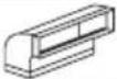 | 4" x 14" 90 Degree | 14 | ||
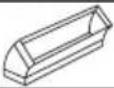 | 4" x 14" 45 Degree | 8 | ||
 | 4" x 14" x 8" Round | 2 | ||
 | 4" x 14" x 8" 90 Degree | 4 | ||
 | 8" Round Wall Cap w Damper | 24 | ||
 | 4" x 14" Wall Cap w Damper | 24 | ||
 | 8" Round Roof Cap | 33 | ||
| TOTAL EQUIVALENT FEET SHOULD BE LESS THAN 100 | ||||
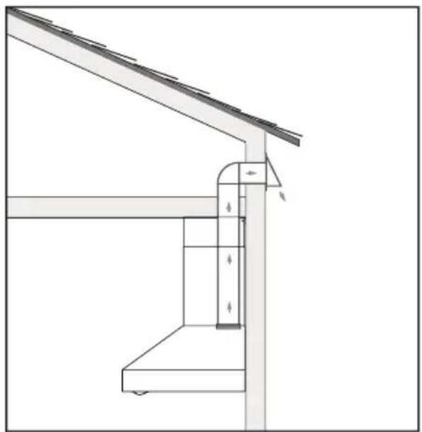
YPICAL INSTALLATION EXAMPLES
natural_image
Technical line drawing of a structural support frame with no visible text or symbolsWALL EXHAUST ROOF EXHAUST

natural_image
Architectural diagram showing a roof structure with a chimney and support frame (no text or symbols)
natural_image
Architectural line drawing of a roof structure with support beams and a door (no text or symbols)GRID EXHAUST
RECIRCULATION EXHAUST MUST BE RE- TURNED TO THE SPACE
DIMENSIONS
Front of hood > Side of hood

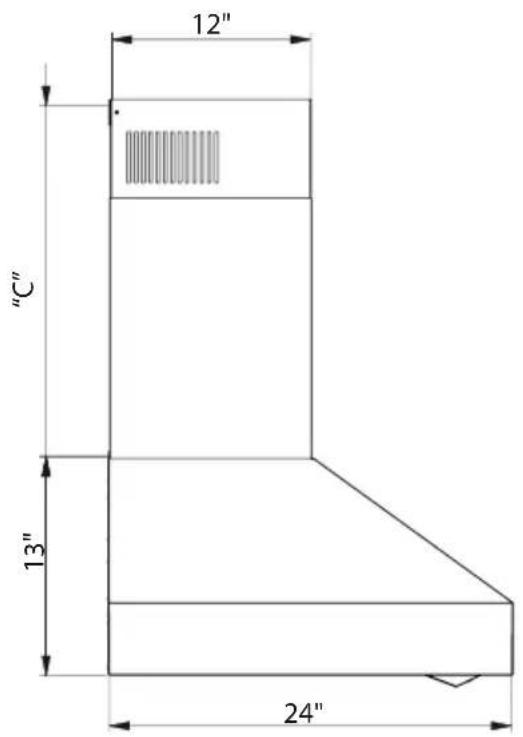
| MODEL A C | ||
| XOVV236KSE | 36" | Vented: Min 16" - Max 31" |
| XOVV242KSE | 42" | |
| XOVV248KSE | 48" |
Top of hood

HIGHS AND LOWS

All range hoods have a recommended range of installation height over the cooking surface.
It is important to install the hood at the proper mounting height. Hoods mounted too low could result in heat damage and fire hazard; while hoods mounted too high will be hard to reach and will lose its performance and efficiency.
INSTALLATION
- Before fixing the hood to the wall, proceed with the installation of the fringe H and secure it with screws O.

INSTALLATION
- Insert screws "A" and dowels into the wall according to the measurements indicated on the drilling template, taking care not to tighten them completely (fig. X).
- Position the unit on the wall by hooking it onto the screws "A" previously inserted.
- Securely fasten the hood with safety screws "C". Tighten screws "A" completely.


natural_image
Technical line drawing of a mechanical component with mounting brackets and a central circular feature (no text or symbols)INSTALLATION
- Fasten bracket D to the wall so that it is aligned with the hood with screws C.
- Fasten the decorative chimneys to the hood with screws G.
- Slide the upper decorative chimney onto bracket D and fasten it with screws E.

ELECTRICAL CONNECTION
- Route the power cord to the junction box.
- Using listed conduit fittings and connectors, connect the power supply to the box and each line to the appropriate wire following this color convention:
BLACK = HOT LEG
WHITE = NEUTRAL
Polarity must be observed.
Unit must be properly grounded.
Use a double throw disconnect switch.
- Replace the box cover
- Replace the Anti-grease filters.
All wiring must be in compliance with national electrical code, ANSI/NFPA 70-1999 and all local codes and regulations.

natural_image
Illustration of a hand using a screwdriver to install a component into an open electrical box (no text or symbols present)MAINTENANCE
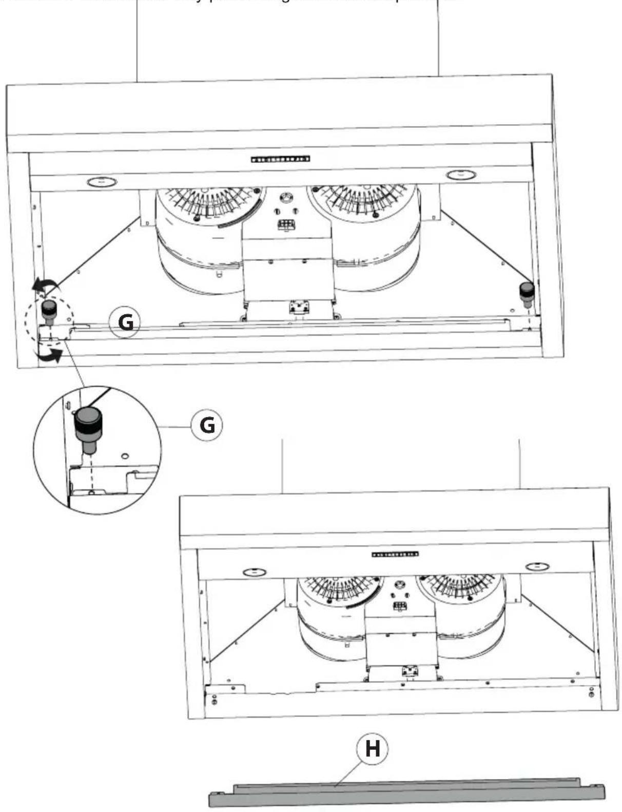
To remove the oil collector tray "H", unscrew the three knobs "G" and pull downwards. Clean the tank and reassemble it by performing the reverse operation.
MAINTENANCE
Regular cleaning and maintenance is the key to long life and peak performance of any equipment.
- The anti-grease filter is used to trap any grease particles suspended in the air, therefore is subject to saturation (the time it takes for the filter to become saturated depends on the way in which the appliance is used). The grease filters should be cleaned frequently. Use a warm detergent solution. Grease filters are a dishwasher safe.

natural_image
Technical line drawing of a cabinet or enclosure with internal grating and ventilation slots (no text or symbols)- To prevent potential fire hazards, the anti-grease filters should be washed a minimum of every 2 months (it is possible to use the dishwasher for this task).
- After a few washes, the colour of the filters may change. This does not mean they have to be replaced. If the replacement and washing instructions are not followed, the anti-grease filters may present a fire hazard.
CLEANING STAINLESS STEEL:
Do not use corrosive detergents, abrasive detergents or oven cleaners.
Do not use any product containing chlorine bleach or any product containing chloride.
Do not use steel wool or abrasive scrubbing pads which will scratch and damage surface.
Cleaning Stainless Steel Clean periodically with warm soapy water and clean cotton cloth or micro fiber cloth. Always rub in the direction of the stainless steel grain. To remove heavier grease build up use a liquid degreaser detergent. After cleaning use a non-abrasive stainless steel polish/cleaners, to polish and buff out the stainless luster and grain. Always rub lightly, with a clean cotton cloth or a micro fiber cloth and buff in the direction of the stainless steel grain.
Any painted surfaces should be cleaned with warm water and detergent only.
MAINTENANCE CONTINUED
LED LIGHT REPLACEMENT
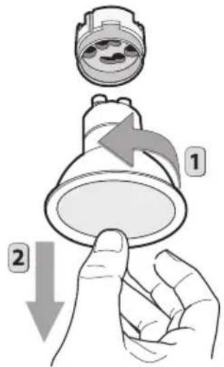
To replace the bulbs, rotate the lamp anticlockwise as shown in Figure. Replace the bulbs with new ones of the same type.
XOPSPK6509
EASY TO OPERATE

Your XO range hood is controlled by these electronic push buttons which illuminate when activated.
BUTTON ✪ Press the button once to switch on the light BUTTON 0: Turns both the Blower and Lights On and Off BUTTON 1: Blower motor operates on LOW speed. BUTTON 2: Blower motor operates on MEDIUM speed. BUTTON 3: Blower motor operates on HIGH speed.
POWER BOOST
Press and Hold BUTTON 3 for 2 seconds.
This will increase airflow to a fourth and even higher speed for 10 minutes. When activated the button will blink to alert you it is running. After 10 minutes the blower speed will return to its last setting. To manually stop the POWER BOOST before 10 minutes has elapsed: Press BUTTON 3 and it will revert to HIGH speed, or Press BUTTON 0 to shut the blower off completely NOTE: The POWER BOOST function will operate even when the hood is off.
BUTTON T: Activates and Deactivates the TIMER Function
Pressing BUTTON T (whether the blower is off or running) will cause the motor to run at LOW speed for 5 minutes before shutting off the blower and lights automatically.
While the TIMER is activated, you can change speed or engage POWER BOOST, the hood will still shut off after 5 minutes.
To manually turn the unit off before 5 minutes has elapsed:
Press BUTTON T or BUTTON 0.
OPTIONAL REMOTE CONTROL (purchased separately)
The remote control must be synchronized prior to use.
To synchronize the remote control with the hood follow these simple steps:
-
Standing near the hood, while it is not running, press and hold BUTTON ⚙️ on the hood for 4 seconds -the button should start to blink for 5 seconds.
-
When the button on the hood starts to blink, Press any button on the remote. The hood and remote are now synchronized.
-
If the synchronization fails for any reason, repeat steps 1 and 2.

natural_image
Hand-drawn sketch of a remote control with four buttons and 'XO' label (no additional text or symbols)XOVREMOTE1
ACCESS PARTS & ACCESSORIES

natural_image
Line drawings of three household appliances: a rectangular tray with heat sinks, a remote control with a 'X90' button, and a light bulb (no text or symbols)RECIRCULATION KITS
FILTERS
REPLACEMENT LIGHTS
REMOTE CONTROLS
ALL OF THESE PARTS AND MORE ARE AVAILABLE, SIMPLY VISIT WWW.XOAPPLIANCE.COM and click on PARTS STORE OR CALL US AT 973-403-8900
WE'VE GOT YOUR BACK
90 DAY LOVE IT or LEAVE IT. For 90 Days all our products are backed by our unique Love it or Leave it Guarantee. TWO-YEAR PARTS & LABOR LIMITED WARRANTY. XO warrants to the original purchaser of every new XO ventilation unit, the cabinet and all parts thereof, to be free from defects in material or workmanship under normal and proper use and maintenance as specified by XO and upon proper installation and start-up in accordance with the instruction packet supplied with each XO unit. XO's obligation under this warranty is limited to a period of two (2) years from the date of original purchase.
WARRANTY CLAIMS. All claims for labor or parts must be made directly through XO. All claims should include: model number and serial number of cabinet, proof of purchase, and date of installation. In case of warranted compressor, the compressor model tag must be returned to XO along with the above listed information.
WHAT IS NOT COVERED BY THIS WARRANTY. XO's sole obligation under this warranty is limited to either repair or replacement of parts, subject to the additional limitations below. This warranty neither assumes nor authorizes any person to assume obligations other than those expressly covered by this warranty. Open box, factory seconds, scratch and dent, floor models and commercial applications are excluded from these warranties.
WARRANTY IS NOT TRANSFERABLE. This warranty is not assignable and applies only in favor of the original purchaser/user at the original installation location. Any such assignment or transfer shall void the warranties herein made and shall void all warranties, express or implied, including any warranty or merchantability or fitness for a particular purpose.
IMPROPER USAGE. XO assumes no liability for parts or labor coverage for component failure or other damages resulting from improper usage or installation or failure to clean and/or maintain product as set forth in the warranty packet provided with the unit. ALTERATION OR NEGLECT. XO is not responsible for the repair or replacement of any parts that XO determines have been subjected after the date of manufacture to alteration, neglect, abuse, misuse, accident, damage during transit or installation, fire, flood, or act of God.
IMPROPER ELECTRICAL CONNECTIONS. XO is not responsible for the repair or replacement of failed or damaged components resulting from electrical power failure, high or low voltage, use of extension cords, or improper grounding of the unit.
YOUR RIGHTS UNDER STATE LAW. This warranty gives you specific legal rights and you may have other rights that vary from state to state. Some states do not allow the exclusion or limitation of consequential damages or a limitation on how long an implied warranty lasts, so the above exclusion or limitation may not apply to you.
OUTSIDE U.S. This warranty does not apply to, and XO is not responsible for, any warranty claims made on products sold or used outside the 48 continental United States.
To obtain service:
Call 973-403-8900 | email service@xoappliance.com | or submit a request on our website
www.xoappliance.com

LOVE IT OR LEAVE IT
100% GUARANTEED



- EVERY THING YOU NEED TO KNOW ABOUT YOUR
- CONGRATULATIONS
- WHERE THINGS ARE
- GETTING READY 5 - 11
- THE INSTALL 12 - 15
- MAINTENANCE 16–18
- OPERATING 19
- PARTS & WARRANTY 20 - 21
- SAFETY FIRST
- Proper maintenance of the Range Hood will assure proper performance of the unit.
- ■ INSTALLATION INSTRUCTIONS
- A FEW SIMPLE RULES TO PLAN YOUR DUCTWORK
- ESTIMATING TOTAL EQUIVALENT FEET IN A DUCT
- YPICAL INSTALLATION EXAMPLES
- DIMENSIONS
- HIGHS AND LOWS
- INSTALLATION
- ELECTRICAL CONNECTION
- MAINTENANCE
- CLEANING STAINLESS STEEL:
- MAINTENANCE CONTINUED
- LED LIGHT REPLACEMENT
- EASY TO OPERATE
- POWER BOOST
- Press and Hold BUTTON 3 for 2 seconds.
- BUTTON T: Activates and Deactivates the TIMER Function
- OPTIONAL REMOTE CONTROL (purchased separately)
- ACCESS PARTS & ACCESSORIES
- WE'VE GOT YOUR BACK
- To obtain service:
Brand : XO
Model : XOVV248KSE
Category : Cap