
HDM2-SPLITPRO-T4K-V3 - Hair dryer Avenview - Free user manual and instructions
Find the device manual for free HDM2-SPLITPRO-T4K-V3 Avenview in PDF.

| Product Type | 4x2 HDMI 2.0a Quad Multiviewer with USB Video Capture |
| Model | HDM2-SPLITPRO-T4K-V3 |
| Input Ports | 4 x HDMI (4K@60) |
| Output Ports | 2 x HDMI (4K@60); 1 x USB-C (video capture); 2 x RCA (audio out) |
| Max Output Resolution | 3840x2160 @ 60Hz (4:4:4 8-bit) |
| USB Capture | USB 3.1 Gen 1, up to 4K2K @30fps (UVC 1.0) |
| HDCP Compliance | HDCP 1.4 / 2.2 |
| Video Bandwidth | 18 Gbps (600 MHz) |
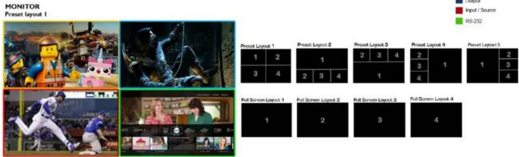
| Supported Layouts | PIP, PAP, Quad, Full screen; customizable with software |
| Control Methods | Front panel, IR remote, RS-232, Ethernet (IP), Cloud; includes software |
| Rotation | 90° left/right per input window |
| Audio Support | LPCM 2/6/8ch, AC3, DTS, Dolby Digital Plus, Dolby TrueHD, DTS-HD; RCA breakout |
| Power Supply | DC 12V / 5A (US/EU, CE/FCC/UL certified) |
| Power Consumption | 22 W (max) |
| Dimensions (Unit) | 440 x 237 x 44 mm (17.3 x 9.3 x 1.7 in) |
| Weight (Unit) | 2.3 kg (5 lbs) |
| Environmental | Operating: 0°C to 40°C; Storage: -20°C to 60°C; Humidity: 20-90% RH (non-condensing) |
| Warranty | 3 years (parts and labor) |
| Package Contents | Main unit, 12V/5A power supply, IR remote, rackmount brackets, user manual, software CD |
Frequently Asked Questions - HDM2-SPLITPRO-T4K-V3 Avenview
User questions about HDM2-SPLITPRO-T4K-V3 Avenview
0 question about this device. Answer the ones you know or ask your own.
Ask a new question about this device
Download the instructions for your Hair dryer in PDF format for free! Find your manual HDM2-SPLITPRO-T4K-V3 - Avenview and take your electronic device back in hand. On this page are published all the documents necessary for the use of your device. HDM2-SPLITPRO-T4K-V3 by Avenview.
USER MANUAL HDM2-SPLITPRO-T4K-V3 Avenview
I.I IMPORTANT SAFEGUARDS.... I
1.2 SAFETY INSTRUCTIONS.... I
1.3 REGULATORY NOTICES FEDERAL COMMUNICATIONS COMMISSION (FCC)....2
- INTRODUCTION....3
2.1 FEATURES 4
2.2 PACKAGE CONTENT....5
2.3 BEFORE INSTALLATION 5
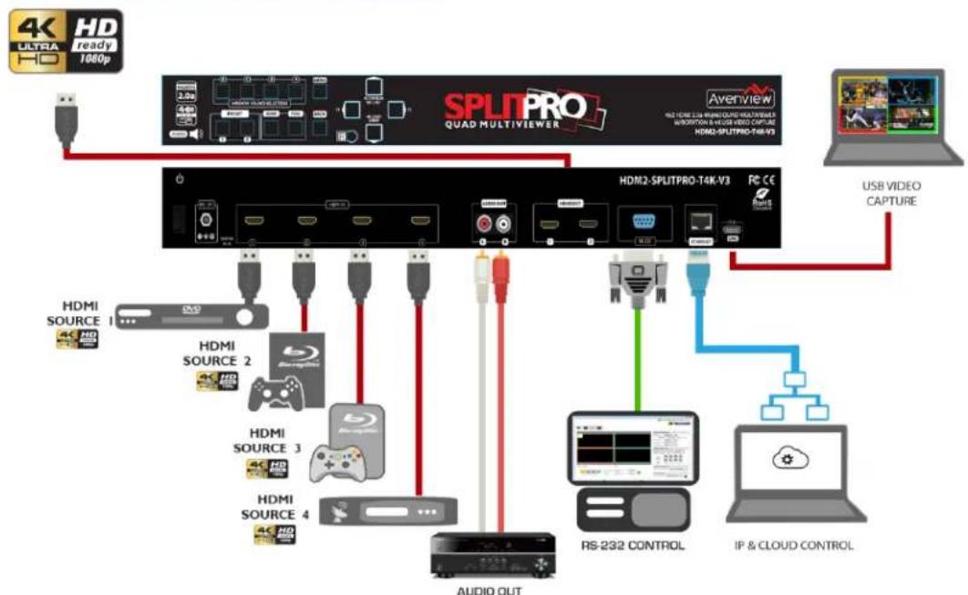
2.4 APPLICATION DIAGRAM 6
- PANELDESCRIPTION....7
3.1 INPUT PANEL (HDM2-SPLITPRO-T4K-V3) FRONT....7
3.2 INPUT PANEL (HDM2-SPLITPRO-T4K-V3) REAR....7
- IR REMOTE CONTROL....8
4.1 INSTALLATION AND CONNECTING CONTROL SOFTWARE....9
4.2 SOFTWARE CONTROL INTERFACE....II
4.3 CLOUD CONTROL 20
- SPECIFICATIONS.... 22
I.I IMPORTANT SAFEGUARDS
Please read all of these instructions carefully before you use the device. Save this manual for future reference.
What the warranty does not cover
• Any product, on which the serial number has been defaced, modified or removed.
• Damage, deterioration or malfunction resulting from:
- Accident, misuse, neglect, fire, water, lightning, or other acts of nature, unauthorized product modification, or failure to follow instructions supplied with the product.
• Repair or attempted repair by anyone not authorized by us.
• Any damage of the product due to shipment.
- Removal or installation of the product.
• Causes external to the product, such as electric power fluctuation or failure.
• Use of supplies or parts not meeting our specifications.
• Normal wear and tear.
• Any other causes which does not relate to a product defect.
- Removal, installation, and set-up service charges.
1.2 SAFETY INSTRUCTIONS
The HDM2-SPLITPRO-T4K-V3 is a 4K UHD 4x2 HDMI 2.0a Quad multiviewer with USB video capture and audio out. It has been tested for conformance to safety regulations and requirements, and has been certified for international use. However, like all electronic equipments, the HDM2-SPLITPRO-T4K-V3 should be used with care. Read the following safety instructions to protect yourself from possible injury and to minimize the risk of damage to the unit.
Do not dismantle the housing or modify the module.
Dismantling the housing or modifying the module may result in electrical shock or burn.
⚠️ Refer all servicing to qualified service personnel.
Do not attempt to service this product yourself as opening or removing housing may expose you to dangerous voltage or other hazards
⚠️ Keep the module away from liquids.
Spillage into the housing may result in fire, electrical shock, or equipment damage. If an object or liquid falls or spills on to the housing, unplug the module immediately.
Have the module checked by a qualified service engineer before using it again.
Do not use liquid or aerosol cleaners to clean this unit. Always unplug the power to the device before cleaning.
1.3 REGULATORY NOTICES FEDERAL COMMUNICATIONS COMMISSION (FCC)
This equipment has been tested and found to comply with part 15 of the FCC rules. These limits are designed to provide reasonable protection against harmful interference in a residential installation.
Any changes or modifications made to this equipment may void the user's authority to operate this equipment.
Warning symbols
Description

ONLY USE THE PROVIDED POWER CABLE OR POWER ADAPTER SUPPLIED. DO NOT TAMPER WITH THE ELECTRICAL PARTS. THIS MAY RESULT IN ELECTRICAL SHOCK OR BURN.

DO NOT TAMPER WITH THE UNIT. DOING SO WILL VOID THE WARRANTY AND CONTINUED USE OF THE PRODUCT.

BEWARE this unit contains static sensitive devices
THE VIDEO BOARDS ARE VERY SENSITIVE TO STATIC. PLEASE ENSURE IF RACK MOUNTED OR INSTALLED ON A SURFACE, IT SHOULD BE IN A GROUNDED ENVIROMENT.

natural_image
Blue circular icon with a white human figure holding an open book (no text or symbols)⚠ WARNING
Read & understand user guide before using this device.
Failure to follow the proper installation instructions could result in damage to the product and preventing expected results.
2. INTRODUCTION
This 4 x2 Quad multiviewer was developed for the purpose of supporting higher output resolution (4K@60) UHD for multiple sources on a single screen with built in USB 3.0 FHD video capture to output 4K video to a computer.
This HDMI device can accept 4 HDMI 4K input digital sources and combine (4) four video signals onto a single HDMI UHD or HD monitor. The user can easily manage each input via the supplied Control Software and create any layout and position of any of the 4 (four) Inputs on a single monitor. This device supports full range of input video resolutions up to 4K and audio RCA breakout supported for external audio distribution systems. Audio channels can be selected to playback with input or can be muted.
Fast Switching – This device can input any 4 HDMI input digital sources and then combine, (4) four video signals onto a single HDMI UHD monitor. The user will benefit with from its processing power to switch between the 8 user defined function using control software via Ethernet or RS232, cloud, 4 IR Remote preset.
Crop – This device can Crop any 4 HDMI input digital sources to remove black bars and then combine, (4) four video signals onto a single HDMI HD monitor. This device can be configured using the supplied Control software via Ethernet or RS232 to set the desired layout on the connected screens.
PIP, PAP, Overlay – This device can input any 4 HDMI digital sources and then combine, (4) four video signals onto a single HDMI HD monitor, which the user can select picture in picture (PIP), picture Aside picture (PAP) or overlay with the supplied Control Software via Ethernet or RS232 to set the desired layout configuration.
Window Scale and Position – The user can easily change the individual channel size and choose different position and layout on the single monitor with the Control Software via Ethernet or RS232 to set the desired layout configuration.
Scalable Rotation (90° & -90°) – The user can easily Rotate/Scale only a single input/window image 90° left and right. This device can be configured with the Control Software, IR Remote, Ethernet, RS232 or front panel buttons.
USB 3.0 Built in 4K Video Capture – The user can capture up to 4K video via the built in USB 3.0 capture to computer.
2.1 FEATURES
- 4 HDMI 4K Inputs & 2 HDMI 4K Outputs (HDMI 2 OUT auto downscale to connected display)
- Output resolution support up to 4K@60 (3840x2160);
- Output resolution support Full HD or to 4K@60 (3840x2160);
- USB 3.1 FHD Video Capture (up to 4K2K @30, UVC 1.0, deinterlace & scaler)
• Supports USB 3.1 Gen 1 (RGB/YUY2/NV12) (capture up to 4K2K@30)
- USB 2.0 (YUY2/NV12) (capture up to 720P@30)
- HDCP 1.4/2.2 compliant
- Fast switching between input channels and combined multiple images on single UHD display;
- Cropping the (4) four HDMI Input Channels;
- Supports PIP, PAP and multi-windows layout configurations;
- Single Input Rotation (90° left & right) functions;
- Background picture & logo support
- Resize, position, zoom & pan and blend output video
- Fade-in-&-out, wipe and dissolve transitions in full screen mode
- 8 preset Hot keys with 4 Custom layouts and 4 Full screen layouts within the supplied control software;
- 4 Custom saved layout buttons via the IR Remote;
- Input resolution support full range of video resolutions up to WUXGA@60 (RB) or full HD1080p;
- Uncompressed 7.1ch digital over HDMI
- RS 232 port for Service mode and firmware upgrade;
- Supports RS 232, Ethernet, IR Remote and front panel buttons and remote control via cloud platform.
- Factory Reset feature.
- Low Latency
2.2 PACKAGE CONTENTS
Before you start the installation of the converter, please check the package contents.
| 1 | HDM2-SPLITPRO-T4K-V3 | X1 |  |
| 2 | POWER SUPPLY (12V 5A) | X1 |  |
| 3 | IR REMOTE | X1 |  |
| 4 | RACKMOUNT BRACKET | X2 |  |
| 5 | USER MANUAL | X1 |  |
| 6 | Software CDSoftware and User guide available onThe Product page on Avenview.com | X1 |
2.3 BEFORE INSTALLATION
- Put the product in an even and stable location. If the product falls down or drops, it may cause an injury or malfunction. Don't place the product in too high temperature (over 50°C), too low temperature (under 0°C) or high humidity.
• Use the DC power adapter with correct specifications. If inappropriate power supply is used, then it may cause a fire. - Do not twist or pull by force ends of the video cable. It can cause malfunction.
HDM2-SPLITPRO-T4K-V3
flowchart
graph TD
    A["4K ULTRA HD ready 1060p"] --> B["SPLITPRO QUAD MULTIVIEWER"]
    B --> C["HDMI2-SPLITPRO-T4K-V3"]
    C --> D["USB VIDEO CAPTURE"]
    C --> E["RS-232 CONTROL"]
    C --> F["IP & CLOUD CONTROL"]
    B --> G["AUDIO OUT"]
    G --> H["HDMI SOURCE 1"]
    G --> I["HDMI SOURCE 2"]
    G --> J["HDMI SOURCE 3"]
    G --> K["HDMI SOURCE 4"]
    B --> L["ACO"]
    C --> M["ACO"]
    C --> N["ACO"]
    C --> O["ACO"]
3.1 INPUT PANEL (HDM2-SPLITPRO-T4K-V3) Front
flowchart
graph LR
    A["1"] --> B["2"]
    B --> C["3"]
    C --> D["4"]
    D --> E["5"]
    E --> F["6"]
    F --> G["7"]
    G --> H["8"]
    H --> I["9"]
    I --> J["10"]
    J --> K["11"]
    K --> L["12"]
    L --> M["13"]
    M --> N["14"]
    N --> O["15"]
    O --> P["16"]
    P --> Q["17"]
    Q --> R["18"]
    R --> S["19"]
    S --> T["20"]
    T --> U["21"]
    U --> V["22"]
    V --> W["23"]
    W --> X["24"]
    X --> Y["25"]
    Y --> Z["26"]
    Z --> AA["27"]
    AA --> AB["28"]
    AB --> AC["29"]
    AC --> AD["30"]
    AD --> AE["31"]
    AE --> AF["32"]
    AF --> AG["33"]
    AG --> AH["34"]
    AH --> AI["35"]
    AI --> AJ["36"]
    AJ --> AK["37"]
    AK --> AL["38"]
    AL --> AM["39"]
    AM --> AN["40"]
    AN --> AO["41"]
    AO --> AP["42"]
    AP --> AQ["43"]
    AQ --> AR["44"]
    AR --> AS["45"]
    AS --> AT["46"]
    AT --> AU["47"]
    AU --> AV["48"]
    AV --> AW["49"]
    AW --> AX["50"]
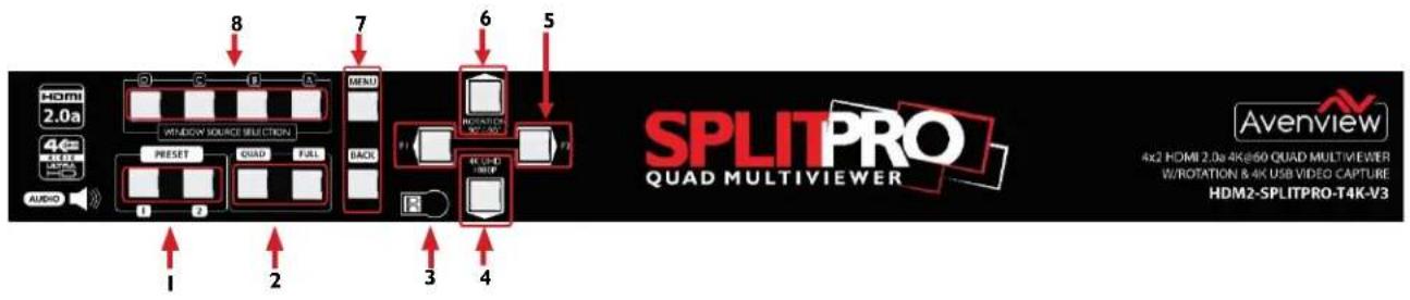
| 1. Preset Layouts | 2.: Quad Screen / Full Screen Mode Buttons |
| 3. IR Sensor:Receive IR commands from IR remote | 4. Resolution Button: 4K UHD/1080p |
| 5. Reserved Buttons: F1 & F2 | 6. Rotation Button: +90 & -90 |
| 7. OSD Menu:Menu control button | 8. Window Source Selection: Source A/B/C/D |
3.2 INPUT PANEL (HDM2-SPLITPRO-T4K-V3) Rear
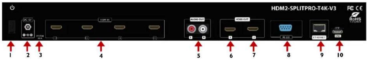
| 1. Power Switch | 2. DC 12V: plug the 12V DC power supply into the unit supplied to an AC 110v outlet. |
| 3. IR Input: 3.5mm socket for plugging in the extension cable of IR receiver | 4. HDMI IN 1-4: Connect up to 4 HDMI devices to the INPUT ports 1-4( Blu-Ray Player, Media Box or PC) |
| 5. Stereo Audio Out L/R: Audio Out | 6. HDMI OUT 1: Connect HDMI 4K monitor/ Display to view the four inputs connected. |
| 7. HDMI OUT 2: Automatically downscale according to EDID of connected display | 8. RS-232: D-Sub 9pin port for sending and controlling the unit by PC/Notebook via RS232 cable. |
| 9. Ethernet: RJ45 jack for sending and controlling the unit by PC/Notebook via Ethernet cable. | 10. USB C: Connect to computer to capture up to 4K video out and Firmware update port |
4.
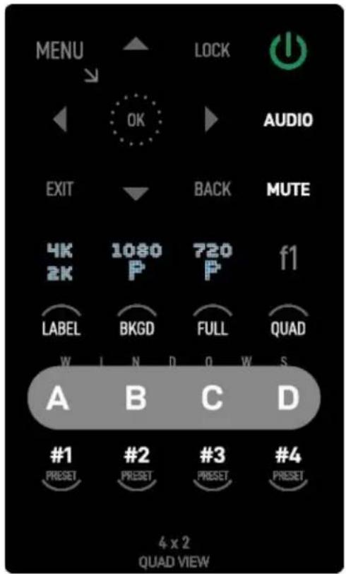
IR REMOTE CONTROL
* Some display/monitor brands the window border may have interference, adjusting the display's motion setting may resolve the interference issue.
| Button | Function |
| POWER | Power on/off the unit |
| LOCK | Lock/unlock the unit |
| ▲ | Navigate up |
| MENU | OSD menu |
| AUDIO | Select audio sources |
| ▶ | Navigate right |
| OK | Trigger the setting |
| ◀ | Navigate left |
| MUTE | Turn off the audio |
| BACK | Back to previous page of OSD menu |
| ▼ | Navigate down |
| EXIT | Exit from the menus |
| F1 | Rotate 90° |
| 720P | Switch output resolution to 720p 60Hz |
| 1080P | Switch output resolution to 1080p 60Hz |
| 4K2K | Switch output resolution to 4K2K 60Hz |
| QUAD | Fast switch to quad-view mode |
| FULL | Fast switch to full screen mode |
| Background | To set up the background picture of window |
| LABEL | Window label ON/OFF |
| A | Select source A to be the input source |
| B | Select source B to be the input source |
| C | Select source C to be the input source |
| D | Select source D to be the input source |
| Preset 1 | User preset 1 |
| Preset 2 | User preset 2 |
| Preset 3 | User preset 3 |
| Preset 4 | User preset 4 |
4.1 INSTALLATION (HDM2-SPLITPRO-T4K-V3)
HARDWARE SETUP
To setup Avenview HDM2-SPLITPRO-T4K-V3 follow these steps below:
I. Mount or fix the HDM2-SPLITPRO-T4K-V3 on a secure shelf, AV rack or steady surface;
2. Ensure the power is off on the HDM2-SPLITPRO-T4K-V3, all source devices and displays that will be connected;
3. Connect your (4) four HDMI cables to the (4) four HDMI sources such as (Media Box, Blu-ray player, Laptop or Set-Top-Box or Gaming device);
4. Connect your HDMI cables to the single HD Displays, LCD or PC monitors that is receiving the video signals.
5. Power on all devices.
6. Connect your computer to HDM2-SPLITPRO-T4K-V3 via RS232 using an RS-232 to USB Cable or Ethernet cable in order to control via RS232 or Telnet.
SERIAL PORT SETTING
RS-232 Wiring (Cross Cable Connection)
| Remote Controller(PC) | |
| PIN | Assignment |
| 1 | NC |
| 2 | TxD |
| 3 | RxD |
| 4 | NC |
| 5 | GND |
| 6 | NC |
| 7 | NC |
| 8 | NC |
| 9 | NC |

| HDM-SPLITPRO-4K-V2 | |
| PIN | Definition |
| 1 | NC |
| 2 | RxD |
| 3 | TxD |
| 4 | NC |
| 5 | GND |
| 6 | NC |
| 7 | NC |
| 8 | NC |
| 9 | NC |

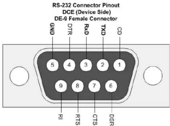
RS-232 SETTINGS
Baud Rate: 115200bps
Data Bit: 8 bits
parity: None
flow Control: None
Stop Bit: I
Control through RS-232 port / Ethernet port
I. Please note when power cycling device, please restart unit at least 5 to 15 seconds after to allow the power capacitors to discharge.
2. The HDM2-SPLITPRO-T4K-V3 PC control software operates with Microsoft Windows 7, 8, 10, 11 through the interface of Ethernet or RS-232 serial control.
3. Through software and COM port you can assign an IP address before connecting via RJ45.
Please NOTE: (Under Microsoft Windows 7, please run software as administrator).
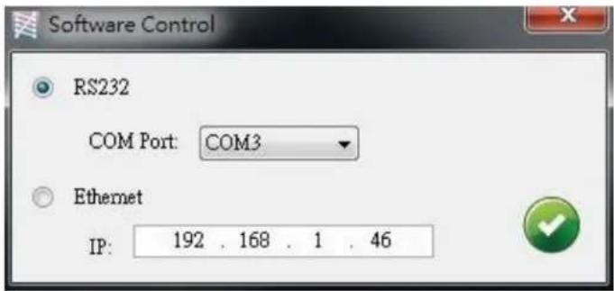
Once the software is installed click on the ICON, the following dialog will pop-up. First time connection, please connect via RS232 serial cable.
RS-232 serial Mode: Use RS-232 to connect the port on device and computer. Select the correct COM port and click the OK button.
Ethernet Mode: Enter the IP address of the device and click the OK button and power cycle the unit.
The default IP: 192.168.1.46
I. Connection Status:
This shows the active connection status. If connected by RS-232 serial Mode device, the icon is 📄. If connected by ethernet . Enter change the control method, by clicking on the button. 📋
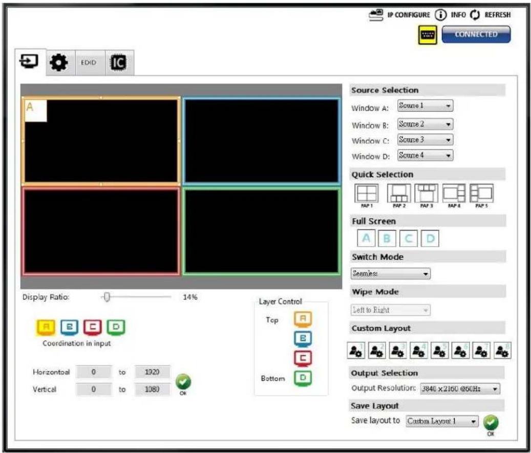
2 Output Settings
Users can set up the designated inputs, to each window A\~D or duplicate, output resolution, PAP predefined layout setting or single input rotation.
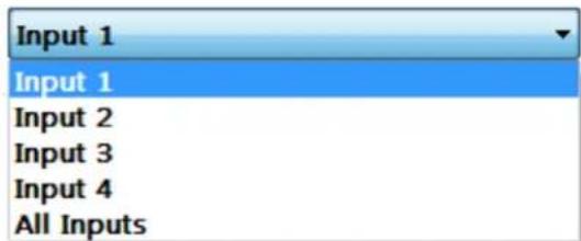
(I) Source Selection
For each display window, you can assign the video source the caption below:
Source Selection

(2) Quick Selection Tabs
Provided in the software 9 default modes (5 PAP and 4 Full Screen) and 8 custom modes for you to create. Switching effects include (Seamless, Fade in/out, Dissolve, Wipe)
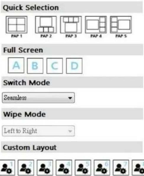
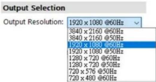
(3) Output Resolution
Set the output resolution from 640x480-4K@60 to match the connected Monitor Timings
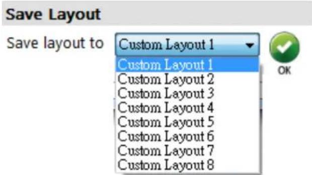
(4) Save Layout
Also the user can define their own 8 custom layouts and save the frequently used scenarios into the flash memory.
(5) Display Panel
As illustrated below, users can resize any window by simply dragging the highlighted box with the mouse and immediately see the results on the attached monitor. The different colors of the frames represent the different inputs for easy identification. The Horizontal and Vertical coordinate shows the position of input source on the screen. In addition, the display ratio can be adjusted to view the layout in software (Zoom in Zoom out).

3. Advanced Setting
(I) Window settings
Users can adjust each display area and input source as desired. To proceed with this function user have to click on the specific channel A, B, C, or D, as indicated by the icons in the control panel as shown above. After the specific channel is chosen, users can click on the "CROP ENABLE" box, then crop the display area of that and other channels. The control panel of the software illustrates by preview on how those settings would to be presented at the output. Using "DIVIDE- Horizontal/Vertical"

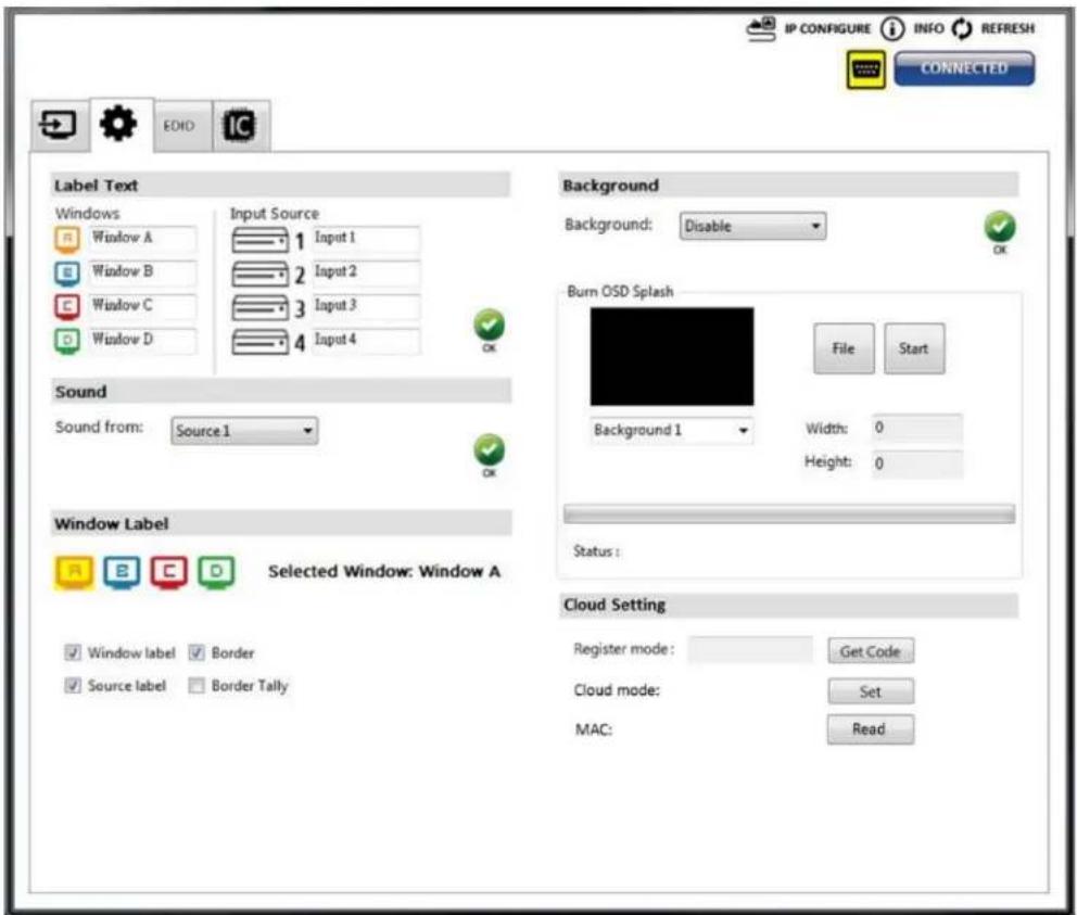
(2) Label Text
In here, users can easily rename /label the input to be shown on the window with the video to identify the input.
(3) Sound
To set and match which audio source to the output video through the R/L channels.

(4) Background
To set up the background of each window. The CS has 4 default pictures for the user to select. To change the default picture, please click the File button to select the picture that would be used choose
Background 1 slot for the image save reference then select
Start

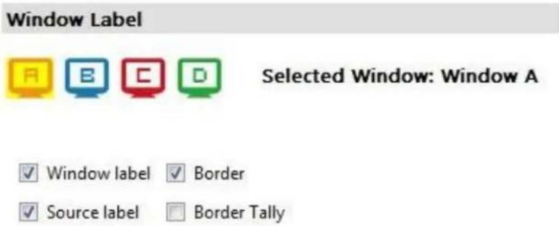
(5) Window Label
Users can simply determine if the window's label/border can be shown or invisible.
4. EDID (Extended Display Identification Data)

(I) Learn EDID from Default
Select Default EDID

Select Input
Click Learn button to learn default EDID.
5. System Setting

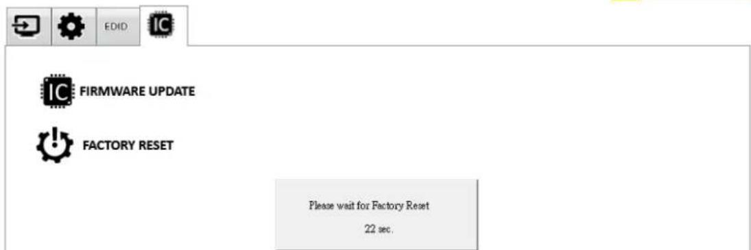
(I) Firmware Update
There are 2 connections that's needed (1) RS-232 on the unit to the PC, (2) USB-C firmware update port to the PC via the USB C cable provided. These will give you 2 new com port items in your windows device manager.
Click button to perform authorized firmware update.
The "Firmware update" window pops up as below.

➢ Please select the correct COM port (corresponding to the USB-C) or click "Scan" button then select the correct COM port (corresponding to the USB-C firmware port) to update the device.
Click "update" button to do firmware update. The unit will power cycle atomically when done.

(2) Factory Reset
➢ Click ⬆ FACTORY RESET button to perform a factory default reset.
The process will take approx. 25 seconds.

6. IP Configure
To use Ethernet control users should click on the

IP CONFIGURE
button to set the network IP range. Please
see the caption below. After the information has been complete, please click the Apply
button.
The default IP: 192.168.1.46

7. Info
Displays the Software and firmware version.
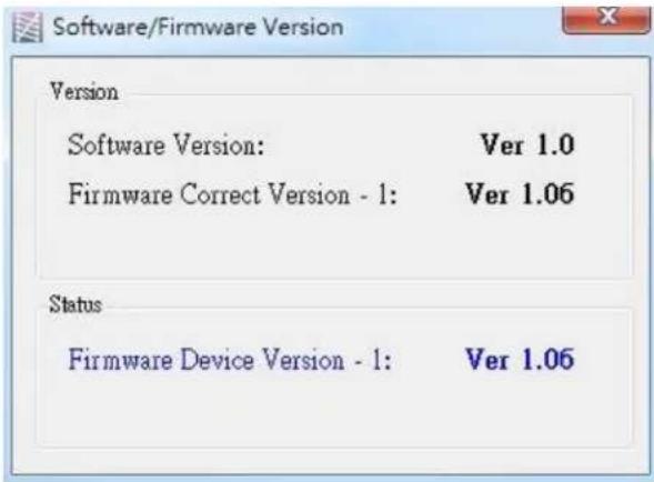
Software/firmware information is subject to change without prior notice
8. Refresh
This function will gather the changes made within software and hardware. Then update the software interface state with its current info.
5.
SPECIFICATIONS
| Item | Description | |
| UNITS | HDM2-SPLITPRO-T4K-V3 | |
| UNIT DESCRIPTION | HDMI 2.0a 4K@60 QUAD MULTIVIEWERW/ROTATION & USB VIDEO CAPTURE | |
| HDCP COMPLIANCE | Yes 1.4, 2.2 | |
| VIDEO BANDWIDTH | HDMI 600MHz [18Gbps] | |
| HDMI COMPLIANCE | Input: HDMI 1.4 /Output: HDMI 2.0a | |
| VIDEO FORMAT SUPPORT | HDMI 2.0 | |
| INPUT SUPPORTED RESOLUTIONS | 720p 50Hz, 720p 60Hz, 1080p 24Hz,1080p 25Hz, 1080p 30Hz, 1080p 50Hz, 1080p 60Hz, 1920X1200 Hz,3840x2160 60 Hz and 4K2K@60 (4:4:4 8bits) | |
| OUTPUT SUPPORTED RESOLUTIONS | 720p 50Hz, 720p 60Hz, 1080p 24Hz,1080p 25Hz, 1080p 30Hz, 1080p 50Hz, 1080p 60Hz, 1920X1200 Hz,3840x216O 60 Hz and 4K2K@60 (4:4:4 8bits) | |
| USB VIDEO SUPPORT | Up to 4K2K@30Hz | |
| USB VIDEO FORMAT | YUY2 (USB3.0), MJPG (USB2.0/3.0) | |
| USB CONNECTOR | USB 3.0 Type A (SuperSpeed USB) | |
| AUDIO SUPPORT | LPCM 2CH, 6CH, 8CH/AC3/DTS/Dolby Digital Plus/ Dolby TruHD/DTS-HD | |
| INPUT | 4x HDMI + 1xRS-232 + 1x RJ-45(Ethernet) + 1x 3.5mm (IR) | |
| OUTPUT | 2x HDMI + 1x USB-C + 2x RCA | |
| CONTROL | RS 232 / IP Control / IR / Front Panel | |
| RJ45 CONNECTOR | WE/SS 8P8C with 2 LED indicators | |
| ESD PROTECTION | Human body model±15kV [air-gap discharge] & ± 8kV [contact discharge] | |
| WEIGHT | Unit: 2.3 kg [5 lbs] | Package: 3.5 kg [7.8 lbs] |
| DIMENSIONS (L X W X H) | Unit (Metal enclosure): 440 x 237 x 44mm [1'4" x 9.3" x 1.7"]Package: 526 x 318 x 156mm [1'7" x 12.5" x 6.1"] | |
| POWER SUPPLY | 12V/5A DC (US/EU standards, CE/FCC/UL certified) | |
| POWER CONSUMPTION | 22W (max) | |
Environmental
| OPERATING TEMPERATURE | 32° ~ 104°F (0° to 40°C) |
| STORAGE TEMPERATURE | -4° ~ 140°F (-20° ~ 60°C) |
| RELATIVE HUMIDITY | 20~90% RH (no condensation) |
Arenview Warranty Certificate
AVENVIEW CORP. ("Avenview") warrants Avenview-branded product(s) contained in the original packaging against defects in materials and workmanship when used normally in accordance with Avenview's enclosed manual guidelines for a period of THREE (3) YEARS from the date of original retail purchase - Warranty Period. Avenview's published guidelines include but are not limited to information contained in technical specifications, user manuals and service communications.
LABOR: During the Warranty Period of THREE (3) YEARS, Avenview will repair or replace the product(s) at no cost using new or used parts equivalent to novel performance and reliability if the product(s) is determined to have abide by Avenview's published guidelines. Cost of Labor applicable to product(s) after Warranty Period. For labor costs, please contact support@avenview.com.
PARTS: During the Warranty Period of THREE (3) YEARS, Avenview will supply new or rebuilt replacements in exchange for defective parts of the product(s) at no cost if the product(s) is determined to have abide by Avenview's published guidelines. Cost of Parts applicable to product(s) after Warranty Period. For part(s) costs, please contact support@avenview.com.
To obtain Warranty: (a) proof of purchase in the form of a bill of sale or received invoice reflecting that the registered product(s) is within warranty period must be presented to obtain warranty service; (b) product(s) must be registered at time of purchase. Failure to do so will result in applicable parts and labor charges. Returning product(s) must be shipped in Avenview's original packaging or in packaging pertaining equal degree of protection to Avenview's. Both Avenview and purchaser are responsible for freight charges and brokerages when shipping the product(s) to the receiver.
NOT COVERED BY THIS WARRANTY
This warranty does not apply to any non-Avenview branded product(s); non-registered Avenview product(s). This warranty does not apply: (a) to cosmetic damage, including but not limited to scratches, dents and broken cords; (b) to damage caused by use with another product; (c) to damage caused by accident, abuse, misuse, liquid contact, fire, earthquake or other external cause; (d) to damage caused by operating the Avenview product(s) outside Avenview's manuals or guidelines; (e) to damage caused by service performed by anyone who is not a representative of Avenview or an Avenview authorized personnel; (f) to defects caused by normal wear and tear or otherwise due to the normal aging of the Avenview product(s), or (g) if any serial number has been removed or defaced from the Avenview product(s).
AVENVIEW IS NOT LIABLE FOR DIRECT, SPECIAL, INCIDENTAL OR CONSEQUENTIAL DAMAGES RESULTING FROM ANY BREACH OF WARRANTY OR CONDITION, OR UNDER ANY OTHER LEGAL THEORY, INCLUDING BUT NOT LIMITED TO LOSS OF USE; LOSS OF REVENUE; LOSS OF ACTUAL OR ANTICIPATED PROFITS (INCLUDING LOSS OF PROFITS ON CONTRACTS); LOSS OF THE USE OF MONEY; LOSS OF ANTICIPATED SAVINGS; LOSS OF BUSINESS; LOSS OF OPPORTUNITY; LOSS OF GOODWILL; LOSS OF REPUTATION; LOSS OF DAMAGE TO, COMPROMISE OR CORRUPTION OF DATA; OR ANY INDIRECT OR CONSEQUENTIAL LOSS OR DAMAGE REPAIR OR REPLACEMENT AS PROVIDED UNDER THIS WARRANTY IS THE EXCLUSIVE REMEDY OF THE CONSUMER.
Some states do not allow the inclusion or limitation of incidental or consequential damages, or allow limitations on duration implements of the Warranty Period; therefore, the above limitations or exclusions may not be applicable to you. This warranty gives you specific legal rights, and you may have other rights which vary from state to state.

1100 Military Road, Kenmore, NY 14217 1.866.508.0269

Avenview
Control Your Video
TECHNICAL SUPPORT
CONTACT US

Phone: 1 (866) 508 0269

Email: support@avenview.com

natural_image
Illustration of a globe with headphones and a headset, symbolizing global communication or internet (no text or symbols present)Avenview Canada
151 Esna Park Drive, Unit 11-12
Markham, ON L3R 3B1
While every precaution has been taken in the preparation of this document, Avenview Inc. assumes no liability with respect to the operation or use of Avenview hardware, software or other products and documentation described herein, for any act or omission of Avenview concerning such products or this documentation, for any interruption of service, loss or interruption of business, loss of anticipatory profits, or for punitive, incidental or consequential damages in connection with the furnishing, performance, or use of the Avenview hardware, software, or other products and documentation provided herein.
Avenview Inc. reserves the right to make changes without further notice to a product or system described herein to improve reliability, function or design. With respect to Avenview products which this document relates, Avenview disclaims all express or implied warranties regarding such products, including but not limited to, the implied warranties of merchantability, fitness for a particular purpose, and non-infringement.


- I.I IMPORTANT SAFEGUARDS
- What the warranty does not cover
- SAFETY INSTRUCTIONS
- REGULATORY NOTICES FEDERAL COMMUNICATIONS COMMISSION (FCC)
- Warning symbols
- Description
- ⚠ WARNING
- INTRODUCTION
- FEATURES
- PACKAGE CONTENTS
- BEFORE INSTALLATION
- INPUT PANEL (HDM2-SPLITPRO-T4K-V3) Front
- INPUT PANEL (HDM2-SPLITPRO-T4K-V3) Rear
- 4.
- IR REMOTE CONTROL
- INSTALLATION (HDM2-SPLITPRO-T4K-V3)
- HARDWARE SETUP
- SERIAL PORT SETTING
- Control through RS-232 port / Ethernet port
- Connection Status:
- Output Settings
- Source Selection
- Source Selection
- Quick Selection Tabs
- Output Resolution
- Save Layout
- Display Panel
- Advanced Setting
- Window settings
- Label Text
- Sound
- Background
- Window Label
- EDID (Extended Display Identification Data)
- Learn EDID from Default
- System Setting
- Firmware Update
- IP Configure
- IP CONFIGURE
- Info
- Refresh
- SPECIFICATIONS
- Arenview Warranty Certificate
- NOT COVERED BY THIS WARRANTY
- Avenview
- TECHNICAL SUPPORT
- CONTACT US
- Avenview Canada
Brand : Avenview
Model : HDM2-SPLITPRO-T4K-V3
Category : Hair dryer