WV-QJB506 - Unspecified i-PRO - Free user manual and instructions
Find the device manual for free WV-QJB506 i-PRO in PDF.

User questions about WV-QJB506 i-PRO
0 question about this device. Answer the ones you know or ask your own.
Ask a new question about this device
Download the instructions for your Unspecified in PDF format for free! Find your manual WV-QJB506 - i-PRO and take your electronic device back in hand. On this page are published all the documents necessary for the use of your device. WV-QJB506 by i-PRO.
USER MANUAL WV-QJB506 i-PRO
Included Installation Instructions
Base Bracket
Model No. WV-QJB506

natural_image
Technical line drawing of a curved mechanical component with internal parts (no text or symbols)- Before attempting to connect or install this product, please read these instructions carefully and save this manual for future use.
- The external appearance and other parts shown in this manual may differ from the actual product within the scope that will not interfere with normal use due to improvement of the product.
i-PRO Co., Ltd. assumes no responsibility for injuries or property damage resulting from failures arising out of improper installation or operation inconsistent with this documentation.
“

i-PRO Co., Ltd.
https://www.i-pro.com/
Caution:
- Before attempting to connect or operate this product, please read these instructions carefully.
Notice:
- This product is not suitable for use in locations where children are likely to be present.
- Do not install this product in locations where ordinary persons can easily reach.
- For information about screws and other parts required for installation, refer to the corresponding section of this document.
Precautions
■ Do not use this bracket except with suitable cameras.
Failure to observe this may cause a drop resulting in injury or accidents.
■ Refer installation work to the dealer.
Installation work requires technique and experience.
Failure to observe this may cause fire, electric shock, injury, or damage to the product.
Be sure to consult the dealer.
■ The screws and bolts must be tightened to the specified torque.
Failure to observe this may cause a drop resulting in injury or accidents.
- Install the product accurately and securely on the installation surface in accordance with the installation instructions.
Failure to observe this may cause injury or accidents.
■ Do not rub the edges of metal parts with your hand.
Failure to observe this may cause injury.
When using this product, also read the “Precautions” described in the operating instructions for the camera to be attached.
Preface
This product is a base bracket for a camera.
Use this product when installing the camera to the installation surface and when using a conduit to make wiring.

The latest information about the supported cameras
Specifications
| Ambient operating temperature: | -50 °C to +60 °C {−58 °F to +140 °F} |
| Dimensions: 197 mm (W) × 50 mm (H) × 138 mm (D){7-3/4 inches (W) × 1-31/32 inches (H) × 5-7/16 inches (D)} | |
| Mass: Approx. 490 g {1.08 lbs} | |
| Finish: Aluminum die cast, Black | |
Precautions for installation
In order to prevent injury, this product must be securely mounted to the installation surface according to Installation Guide.
■ Make sure to remove this product if it will no longer be used.
Standard Accessories
Camera mounting screw (M5 x 20 mm {25/32 inches}) ...... 3 pcs. (of them, 1 for spare)
Other items that are needed (not included)
- Mounting screws
| Installation method Recommended screw*1 | Minimum pull-out strength*2 |
| Directly mount this product onto the installation surface. | M5 × 30 mm {1-3/16 inches}*3× 3 pcs. |
| 196 N {44 lbf} |
*1 Select screws according to the material of the location that the camera will be mounted to. In this case, wood screws and nails should not be used.
*2 This value indicates the minimum pull-out strength required value per screw.
For information about the minimum pull-out strength, refer to our technical information website
*3 The screw length is an example when installing the camera on a robust ceiling with a thickness of 35 mm {1-3/8 inches} or more.
Parts and functions
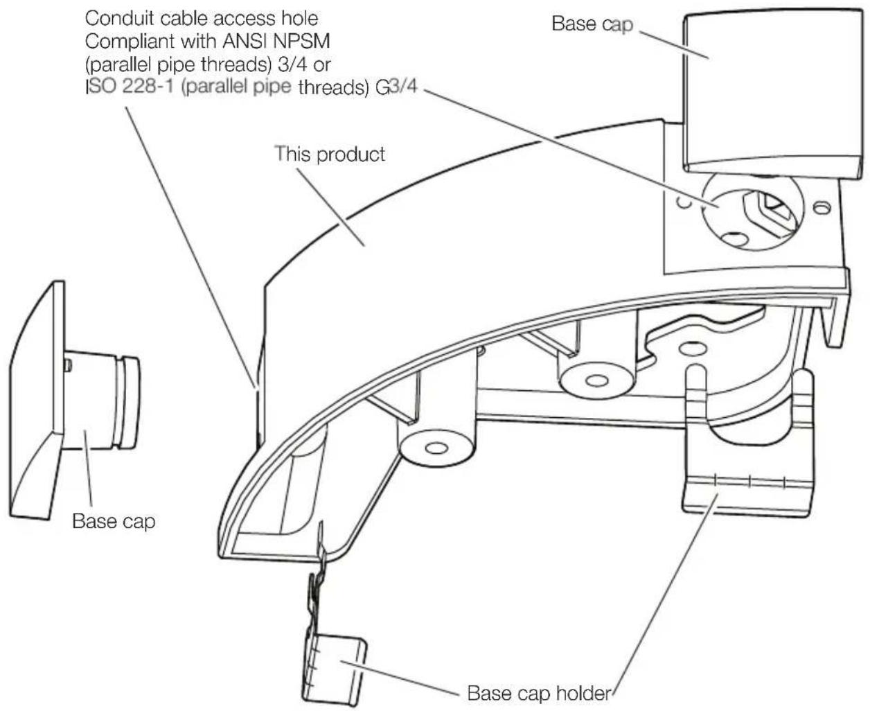
text_image
Conduit cable access hole Compliant with ANSI NPSM (parallel pipe threads) 3/4 or ISO 228-1 (parallel pipe threads) G3/4 This product Base cap Base cap holderInstallation
Step 1 | Preparations
Note:
- Refer to the Installation Guide of the camera for more information about preparing to install the camera.
■ When installing the conduit from the left side of this product
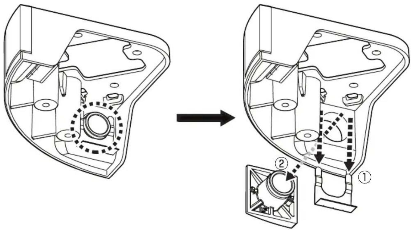
text_image
Technical diagram showing mechanical assembly before and after disassembly, with labeled components and motion arrows■ When installing the conduit from the right side of this product
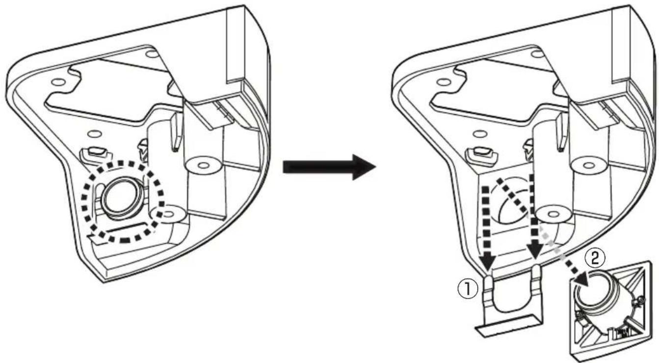
text_image
Technical diagram showing a mechanical assembly before and after modification, with labeled parts ① and ②.Step 2
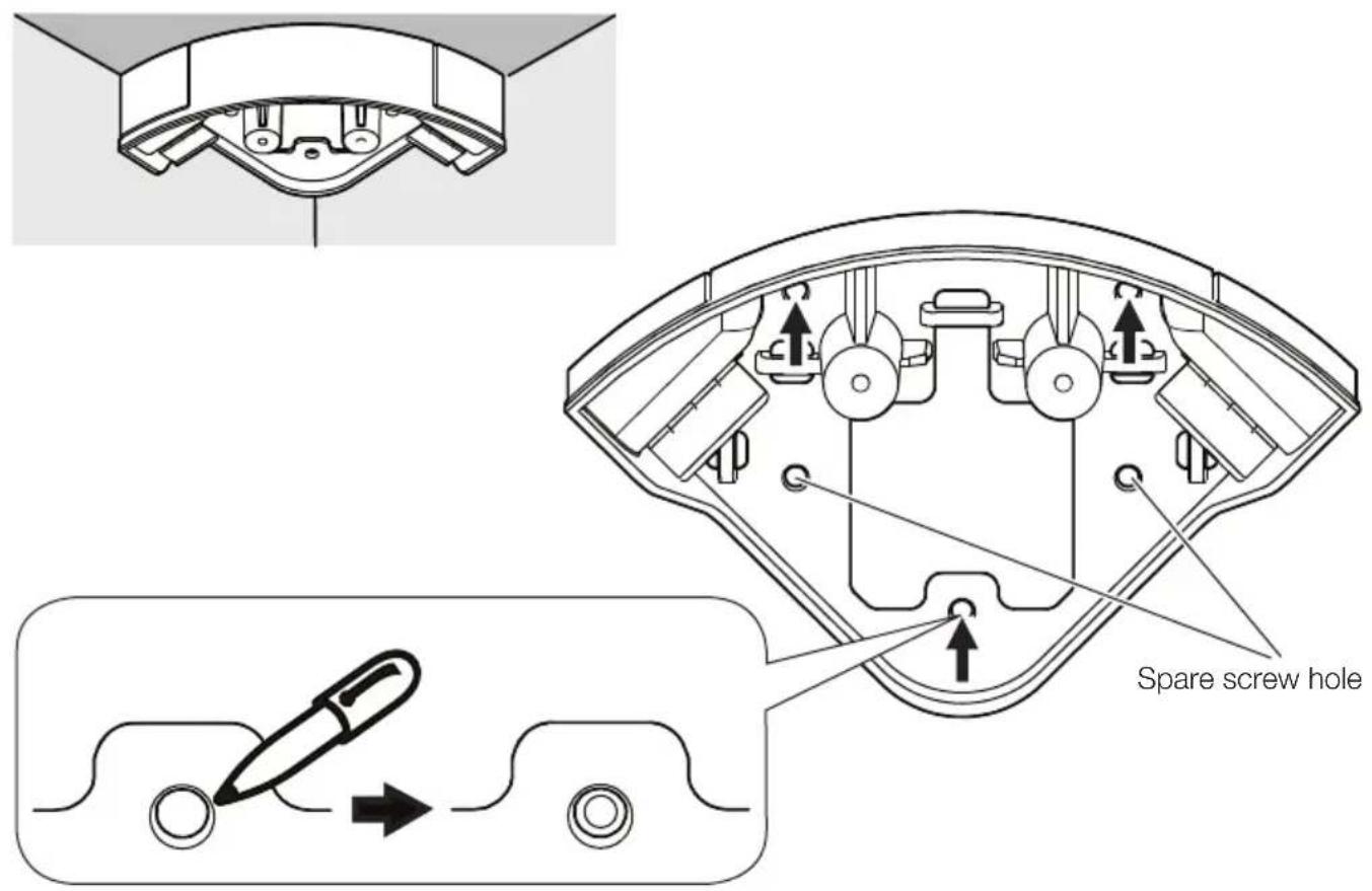
text_image
Spare screw hole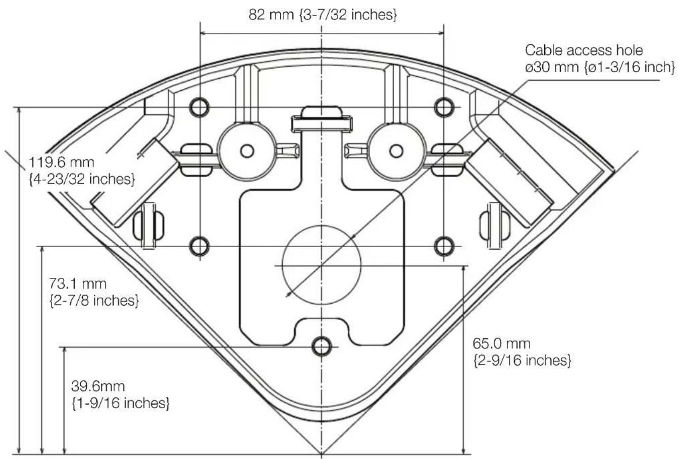
text_image
82 mm {3-7/32 inches} Cable access hole ø30 mm {ø1-3/16 inch} 119.6 mm {4-23/32 inches} 73.1 mm {2-7/8 inches} 65.0 mm {2-9/16 inches} 39.6mm {1-9/16 inches}Step 3
Note:
- The following illustrations explain the case where the conduit is attached from the left side of this product.
- The following is a description of connecting only an Ethernet cable as an example. Refer to the operating instructions of the camera when using a monitor cable and I/O cable.
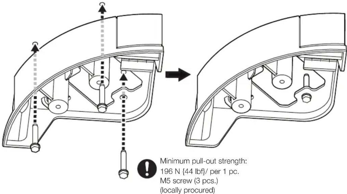
text_image
Minimum pull-out strength: 196 N {44 lbf}/ per 1 pc. M5 screw (3 pcs.) (locally procured)Step 4

natural_image
Technical line drawing of a mechanical assembly with no visible text or symbolsStep 5
Note:
- Select two screw holes to be used for fixing this unit from the four screw holes on the left and right sides of this unit, and remove the mount rubber from those screw holes.
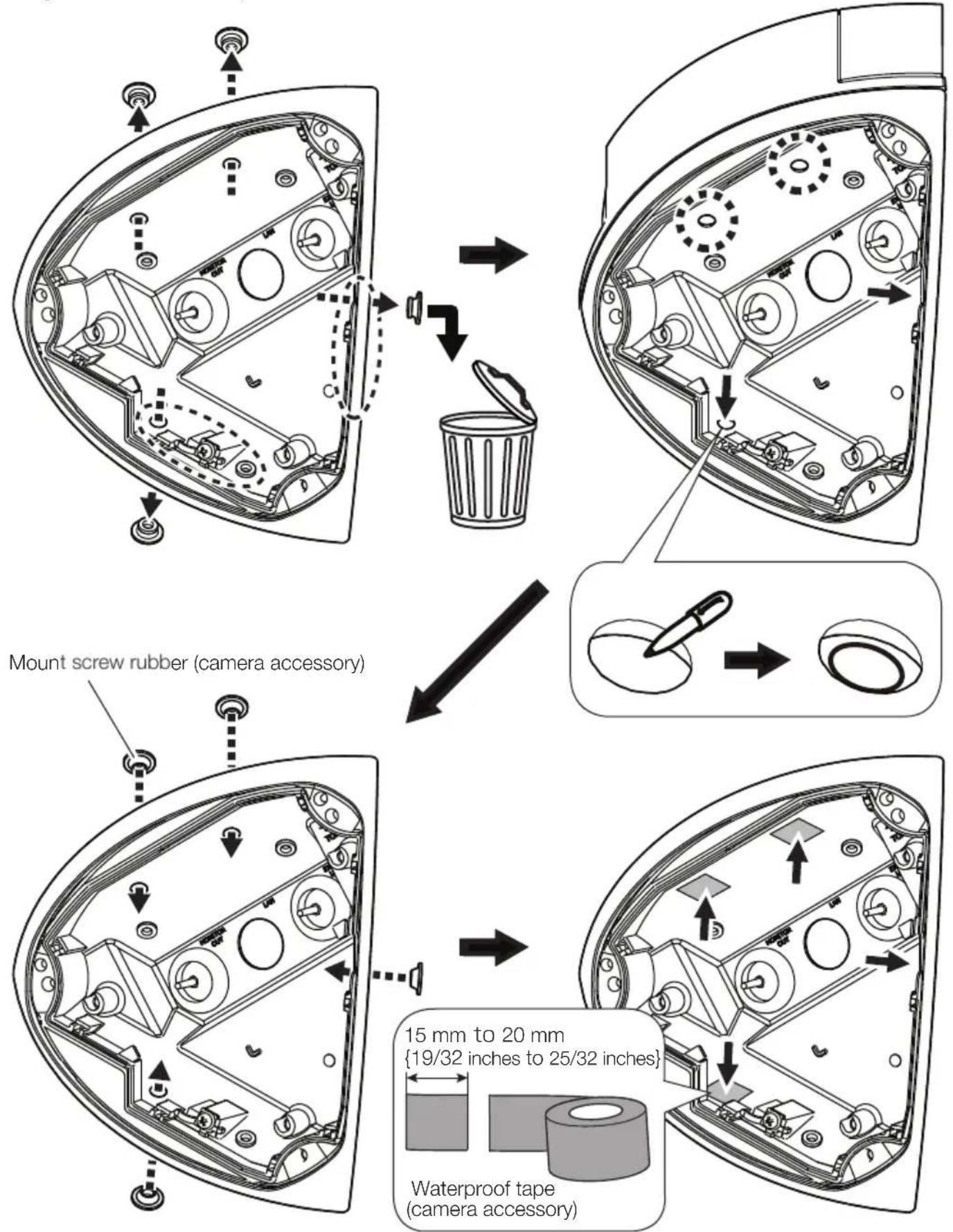
text_image
Mount screw rubber (camera accessory) 15 mm to 20 mm {19/32 inches to 25/32 inches} Waterproof tape retailer accessory)Step 6
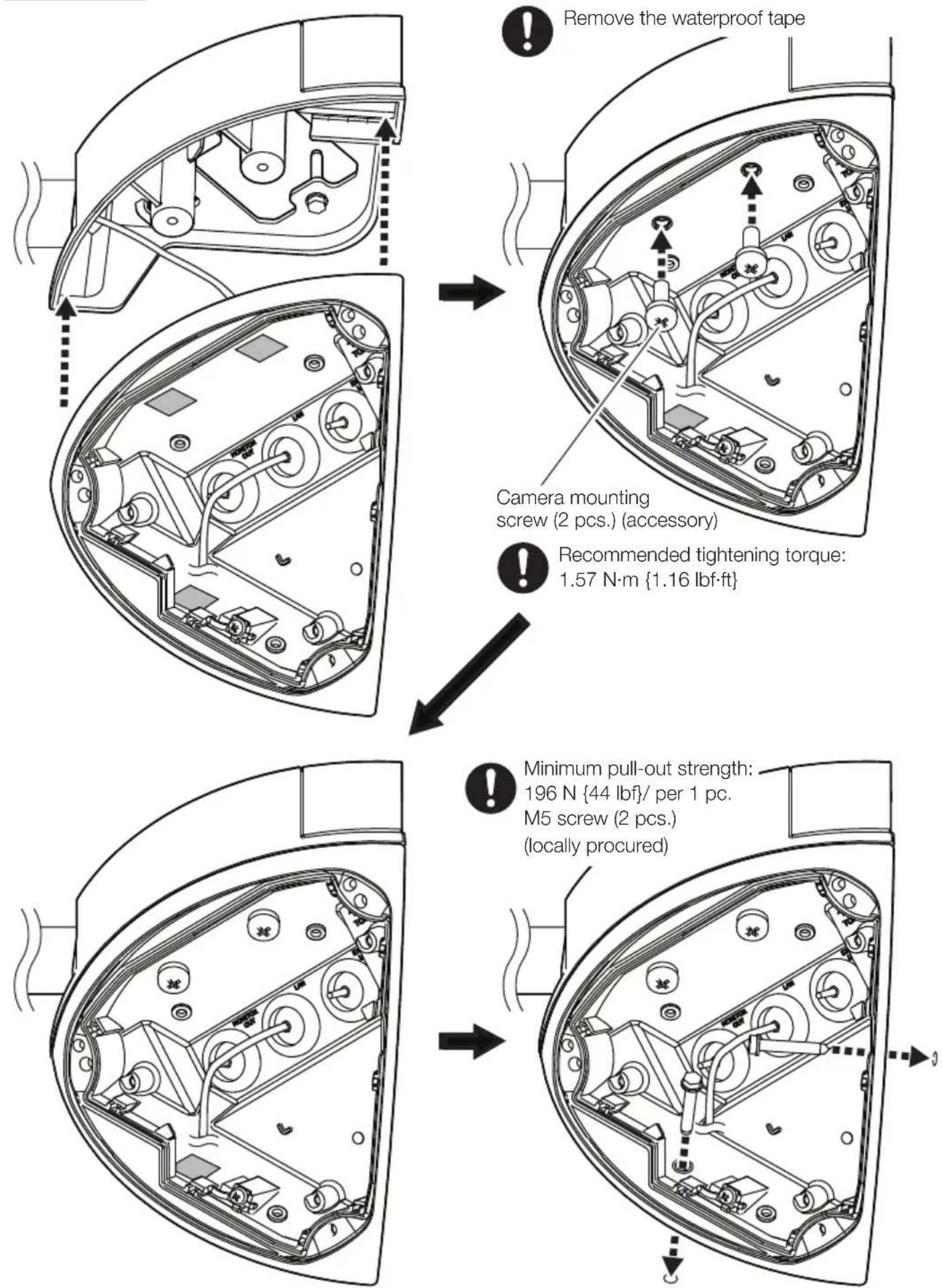
Step 7
Attach the inner case and the front cover to the camera.
Refer to the Installation Guide of the camera for more information about installing the camera.