
RovoRX-HDMI - Unknown AJA - Free user manual and instructions
Find the device manual for free RovoRX-HDMI AJA in PDF.

| Product Type | UltraHD/HD HDBaseT Receiver (Mini-Converter) |
| Model | RovoRX-HDMI |
| Brand | AJA Video Systems |
| Video Input | HDBaseT (RJ45) from RovoCam or compatible HDBaseT transmitter |
| Video Output | 1 x HDMI 1.4b |
| Audio Output | 2 x RCA analog audio outputs |
| Control Interface | RS-232 for SONY VISCA camera control |
| Power Supply | 48VDC external power supply (included) |
| Max Cable Length | Up to 100m (328 ft) with Cat6a cable for video, audio, control, and power |
| Supported Video Formats | 3840x2160p up to 29.97 fps, 1080p up to 59.94 fps, 1080i, 720p, SD |
| Dimensions | Mini-Converter form factor (exact dimensions not specified) |
| Weight | Not specified |
| Operating Temperature | 0°C to 40°C (32°F to 104°F) |
| Storage Temperature | -40°C to 60°C (-40°F to 140°F) |
| Operating Humidity | 10-90% noncondensing |
| Warranty | 5 years for RovoRx-HDMI |
| Compliance | FCC Class B, CE, ICES-003, VCCI, etc. |
| Maintenance | Clean exterior with dry cloth; no user-serviceable parts inside |
| Safety | Do not open chassis; refer servicing to qualified personnel |
| Included Accessories | 48VDC power supply with AC cable |
Frequently Asked Questions - RovoRX-HDMI AJA
User questions about RovoRX-HDMI AJA
0 question about this device. Answer the ones you know or ask your own.
Ask a new question about this device
Download the instructions for your Unknown in PDF format for free! Find your manual RovoRX-HDMI - AJA and take your electronic device back in hand. On this page are published all the documents necessary for the use of your device. RovoRX-HDMI by AJA.
USER MANUAL RovoRX-HDMI AJA
Installation and Operation Guide
Trademarks
AJA^® and Because it matters. are registered trademarks of AJA Video Systems, Inc. for use with most AJA products. AJA^TM is a trademark of AJA Video Systems, Inc. for use with recorder, router, software and camera products. Because it matters. is a trademark of AJA Video Systems, Inc. for use with camera products.
CION ^® , Corvid Ultra ^® , Io ^® , Ki Pro ^® , KONA ^® , KUMO ^® , ROI ^® and T-Tap ^® are registered trademarks of AJA Video Systems, Inc.
AJA Control Room™, KiStor™, Science of the Beautiful™, TruScale™, TruZoom™, V2Analog™ and V2Digital™ are trademarks of AJA Video Systems, Inc.
AirPort, Apple, Apple logo, AppleShare, AppleTalk, FireWire, iPod, iPod touch, Mac, Macintosh and ProRes, are registered trademarks of Apple Inc. Final Cut Pro, QuickTime and QuickTime logo are trademarks of Apple Inc.
Avid, Avid DNxHD and Media Composer are registered trademarks of Avid Technology, Inc.
Adobe is a registered trademark of Adobe Systems Incorporated in the United States and/or other countries.
HDMI, the HDMI logo and High-Definition Multimedia Interface are trademarks or registered trademarks of HDMI Licensing, LLC.
DVI is a registered trademark of DDWG.
TASCAM is a registered trademark of TEAC Corporation.
Dolby and the double-D Dolby logo are registered trademarks of Dolby Laboratories Licensing Corporation.
openGear® Ross, ROSS, ROSS®, and MLE are registered trademarks of Ross Video.
Dashboard Control System™ is a trademark of Ross Video.
All other trademarks are the property of their respective holders.
Copyright
Copyright © 2017 AJA Video Systems, Inc. All rights reserved. All information in this manual is subject to change without notice. No part of the document may be reproduced or transmitted in any form, or by any means, electronic or mechanical, including photocopying or recording, without the express written permission of AJA Video Systems, Inc.
Contacting AJA Support
When calling for support, have all information at hand prior to calling. To contact AJA for sales or support, use any of the following methods:
Telephone +1.530.271.3190
FAX +1.530.271.3140
Web https://www.aja.com
Support Email support@aja.com
Sales Email sales@aja.com
Contents
Notices 2
Trademarks 2
Copyright 2
Contacting AJA Support 2
Chapter 1 – RovoCam System Introduction .....4
System Overview. 4
Features 6
Hardware 6
Software 7
Warranty 7
What's In The Boxes? 7
In This Manual 8
Chapter 2 – RovoCam .....9
Overview....9
Block Diagram 9
Connectors 9
Dimensions 10
Camera Installation 10
Tripod Plate 10
Cold Shoe. 11
Enclosure....11
General Precautions.... 11
Operation. 11
Operation and Storage Locations 11
Care of the Unit 12
Other. 12
Phenomena Specific to CMOS Image Sensors 12
Phenomena Specific to Lenses 12
Chapter 3 – Operation with RovoRx ..... 13
RovoRx-HDMI....13
RovoRx-SDI 13
Chapter 4 – Operation with RovoControl ..... 14
RovoControl Overview 14
Chapter 5 – Third Party Control Solutions. ..... 15
Overview....15
RocoSoft 15
Serial Port Tool 15
Appendix A – Specifications ..... 16
RovoCam Tech Specs 16
Appendix B – Safety and Compliance ..... 19
Warranty and Liability Information....25
Limited Warranty. 25
Limitation of Liability 25
Index. 26
Chapter 1 – RovoCam System Introduction

natural_image
Exterior view of a RovoRx-HDMI HDSAMT device and its AJA sensor module (no signage text in focus)System Overview
RovoCam is AJA's first compact block camera for industrial, corporate, security, ProAV and broadcast applications.
RovoRx-HDMI and RovoRx-SDI are companion receiver units that offer the simplest reception option for RovoCam. They are UltraHD/HD HDBaseT Receivers with integrated HDMI or SDI video and audio outputs specifically designed to receive RovoCam's output and drive displays. This allows one to receive the RovoCam's output up to 100m (328') away from the camera itself and display the output on a display wherever needed, greatly simplifying workflows and systems integration.
A single Cat5e/6 cable carries all uncompressed video, two-channel audio, VISCA camera control, and power for the simplest installation ever due to RovoCam's integrated HDBaseT interface. Delivering this much functionality and power with single cable connectivity dramatically simplifies the installation, camera setup and footprint requirements.
RovoRx-SDI includes a frame sync function which supports using a RovoCam camera feed in a video production environment.
RovoRx-HDMI and RovoRx-SDI can also be used with any compatible HDBaseT transmitter, not just RovoCam.
NOTE: The HDBaseT format uses RJ45 connectors but does not support Ethernet. HDBaseT is point-to-point signal transport.
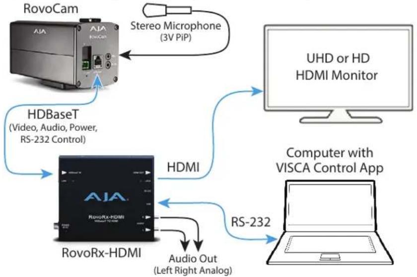
Figure 1. RovoCam System Diagram, with Audio and Computer
flowchart
graph TD
    A["RovoCam"] -->|Stereo Microphone (3V PiP)| B["UHD or HD HDMI Monitor"]
    C["HDBaseT (Video, Audio, Power, RS-232 Control)"] --> D["HDMI"]
    E["RovoRx-HDMI"] -->|Audio Out (Left Right Analog)| F["Computer with VISCA Control App"]
    D -->|RS-232| F
RovoCam can receive power from the RovoRx over a Cat5e/6 cable (Figure 1), or powered locally using its 12VDC connector (Figure 2).
Figure 2. RovoCam System Diagram, with Hardware Controller

flowchart
graph TD
    A["RovoCam"] -->|Local Power| B["HDBaseT (Video, RS-232 Control)"]
    B --> C["RovoRx-HDMI"]
    C -->|HDMI| D["UHD or HD HDMI Monitor"]
    C -->|RS-232| E["VISCA Hardware Controller"]
Figure 3. Two RovoCam System Diagram, with RovoRx-SDIs

flowchart
graph TD
    A["RovoCam"] -->|HDBaseT| B["UHD or HD HDMI Monitor"]
    C["RovoCam"] -->|HDBaseT| D["RovoRx-SDI"]
    E["Big Screen Stadium Display"] --> F["Video Switcher"]
    B -->|RS-232| G["RovoRx-SDI"]
    B -->|Ref In| G
    D -->|RS-232| G
    D -->|UltraHD SDI Out| G
    D -->|UltraHD SDI Out| H["Computer with RovoControl"]
    G --> I["Video Switcher"]
    H --> I
    style A fill:#f9f,stroke:#333
    style C fill:#f9f,stroke:#333
    style E fill:#ccf,stroke:#333
    style G fill:#cff,stroke:#333
    style H fill:#ffc,stroke:#333
Features
Hardware
RovoCam
- UltraHD and HD video output (see "Appendix A Specifications" on page 16)
- Sensor
• Progressive scan CMOS, 1/2.3 type Exmor R™, 3840x2160
• 8.93 Mega Pixels
- Zoom Lens
• Focal length: 3.9mm to 46.8mm
- F1.8 to 2.0
• Horizontal Angle of View
- 12x optical zoom
- 12x digital zoom
• 1 x HDBaseT connector (RJ45)
• 1 x Stereo mini audio input (3V PIP) - 1 x 3.5mm TRS connector RS-232
- 48v DC power in
RovoRx-HDMI
• 1 x HDMI 1.4b output
• 2 x RCA analog audio outputs
• 1 x RS-232 for RovoCam control via SONY VISCA
• 1 x HDBaseT connector (RJ45)
• 48VDC power supply (included)
RovoRx-SDI
• 1 x HDMI 1.4b output
• 4x 6G/3G-SDI BNC outputs
- 6G-SDI output of UltraHD/H 60p at 4:2:0 across a single 6G-SDI connector (In case of RovoCam workflows up to 30p due to RovoCam's output)
- Loop through Reference BNC
- 2 x RCA analog audio outputs
- 1 x USB for firmware upgrades
• 1 x RS-232 for RovoCam control via SONY VISCA
• 1 x HDBaseT connector (RJ45)
• 48VDC power supply (included)
Software
- AJA RovoControl software available for download from the AJA website
• RovoCam accepts VISCA camera control - A variety of third-party software controllers are also available. See "Chapter 5 Third Party Control Solutions" on page 15 for more information.
- RovoRx-SDI can use AJA's Mini-Config application for firmware updates and advanced configuration.
Warranty
• Three year AJA warranty on RovoCam
- Five year AJA warranty on RovoRx-HDMI and RovoRx-SDI
What's In The Boxes?
When you unpack your product you'll find the following components:
RovoCam Box
- AJA RovoCam camera
• USB to RS-232 adapter cable - Phoenix/Euroblock style plug-in power adapter (optional use with local power)
RovoRx Box
- AJA RovoRx-HDMI or RovoRx-SDI Mini-Converter
• 48VDC power supply with AC cable
In addition the following item is available from AJA as part of the HB-CABLE-KIT:
• 3.5mm TRS to DB9 adapter cable
NOTE: This cable is also widely available for purchase from other sources.
Please save all packaging for future shipping.
In This Manual
Chapter 1 - Introduces the RovoCam system, briefly describing the components, features, box contents, and system requirements.
Chapter 2 - Describes the RovoCam hardware and connections.
Chapter 3 - Gives a brief overview of the RovoRx-HDMI and RovoRx-SDI hardware.
Chapter 4 - Gives a brief overview of the AJA's RovoControl camera control software.
Chapter 5 - Provides information about RovoCam system third-party control software.
Appendix A - Provides specifications for RovoCam.
Appendix B - Contains important caution, warning, and compliance statements.
Warranty and Index
Chapter 2 – RovoCam

natural_image
Exterior view of a RovoCam industrial device with labeled ports and connectors (no readable text beyond branding)Overview
When using the product, you'll make media cable connections to a variety of equipment based on how the system is being used.
Block Diagram
Figure 4. RovoCam Simplified Block Diagrams

flowchart
graph LR
    A["Image Sensor"] --> B["Image Processor"]
    B --> C["HDBaseT Transmitter"]
    C --> D["+12 VDC"]
    C --> E["+20dB"]
    C --> F["RS-232 Receiver"]
    F --> G["Local RS-232 Control"]
    C --> H["RJ-45 HDBaseT Out RS-232 In Power In"]
    H --> I["Power Distribution"]
    I --> J["+12 VDC"]
    C --> K["Stereo Mic Input"]
    C --> L["USFirmware Interface"]
Connectors
Figure 5. RovoCam Rear View

Dimensions
Figure 6. RovoCam Dimensions

Camera Installation
Tripod Plate
The removable tripod plate can be mounted on the top or bottom of the camera (use the software controlled image flip feature for upside down mounting). The tripod plate has 1/4-20 and 3/8-16 threaded holes and guide pin holes, and is attached to the camera via four 4-40 cap screws, 5/64 hex heads.
Figure 7. Tripod Plate Dimensions

Cold Shoe
The removable cold shoe plate can be mounted on the top of the camera, and can hold a microphone or light. It is held in place with two 2 Phillips head screws.
Enclosure
The small block camera outside dimensions are suitable for installation into a variety of environmental enclosures. Examples of compatible enclosures include:
• SONY SNCUNI (indoor use)
• SONY SNCUNIHB/1 (outdoor use)
Eclipse
When selecting the housing, refer to the dimensional allowance as shown below.
Figure 8. Eclipse Diagram

General Precautions
The following general precautions apply to RovoCam operation.
Operation
Start the camera control software on your computer after you turn on the camera and the image is displayed.
Operation and Storage Locations
Do not shoot images that are extremely bright (e.g., light sources, the sun, etc.) for long periods of time. Do not use or store the camera in the following extreme conditions:
- Extremely hot or cold places (operating temperature (0°C to +55°C (32°F to 131°F))
- Close to generators of powerful electromagnetic radiation such as radio or TV transmitters
- Where it is subject to fluorescent light reflections
- Where it is subject to unstable (flickering, etc.) lighting conditions
- Where it is subject to strong vibration
- Where it is subject to radiation from laser beams
Care of the Unit
Remove dust or dirt on the surface of the lens with a blower (commercially available).
Other
- Design and specifications are subject to change without notice.
- Do not apply excessive voltage. (Use only the specified voltage.) Otherwise, you may get an electric shock or a fire may occur.
- The CMOS image sensor and IC included in this camera may break if exposed to static electricity. When directly handling this camera, wear an antistatic strap, spread a conductive sheet or similar item under your workbench, and take measures to eliminate static electricity.
- In case of abnormal operation, contact AJA support or the store where you purchased the product.
Phenomena Specific to CMOS Image Sensors
The following phenomena that may appear in images are specific to CMOS image sensors. They do not indicate malfunctions.
Rolling Shutter
As CMOS image sensors use shutters that capture images line-by-line, there is a slight time difference between the top and bottom of an image. As a result, images may appear skewed if the camera is moved.
White Flecks
Although the CMOS image sensors are produced with high-precision technologies, fine white flecks may be generated on the screen in rare cases, caused by cosmic rays, etc.
This is related to the principle of CMOS image sensors and is not a malfunction.
The white flecks especially tend to be seen in the following cases:
- When operating at a high environmental temperature
- When you have raised the master gain (sensitivity)
- When operating in Slow-Shutter mode
Aliasing
When fine patterns, stripes, or lines are shot, they may appear jagged or flicker.
Phenomena Specific to Lenses
Ghosting
If a strong light source (e.g., the sun) exists near the incidence angle of the lens, bright spots may appear in the image due to diffuse reflection within the lens.
Chapter 3 – Operation with RovoRx

RovoRx-HDMI
RovoRx-HDMI is an UltraHD/HD HDBaseT receiver with integrated HDMI video and audio outputs specifically designed to receive RovoCam's output. Receive the RovoCam's video and audio up to 100m away from the camera, and output to HDMI TVs and devices. The simple and economical RovoRx-HDMI provides video, audio, control and power transmission using a single CAT cable.
See the separate RovoRx Installation and Operation Guide, available on the AJA website, for detailed information.
RovoRx-SDI
RovoRx-SDI is an UltraHD/HD HDBaseT receiver with integrated SDI video and audio outputs specifically designed to receive RovoCam's output. It also has an HDMI output for ubiquitous UltraHD and HD displays, a DA Mode for distributing multiple SDI signals from an HDBaseT source, and REF in/out that can be Genlocked with other broadcast gear.
See the separate RovoRx Installation and Operation Guide, available on the AJA website, for detailed information.
Chapter 4 – Operation with RovoControl
RovoControl Overview
RovoControl is a free application from AJA that allows easy configuration and Control for RovoCam. RovoControl uniquely offers electronic PTZ for moving an HD 1080p box around the UltraHD frame, allowing Pan and Tilt for HD output.
Download the latest version of RovoControl software from the AJA website for your computer operating system (.msi for Windows, .dmg for Mac).
See the separate RovoControl Installation and Operation Guide, also available on the AJA website, for detailed information.
Chapter 5 – Third Party Control Solutions
Overview
Because the RovoCam system uses the industry standard SONY VISCA camera control protocol, a wide variety of third-party control solutions are available. Refer to the software providers for specific computer system requirements.
Listed below are some providers, products, and links:
NOTE: Some controllers will require a serial null modem to operate with RovoCam.
RocoSoft
- RocoSoft PTZ tester software, free utility download:
http://www.rocosoft.com/download/software/RocosoftPTZCameraTester.EXE
• PTZJoy - PTZ Camera Controller
• PTZJoy Pro-PTZ Camera Controller
• PTZJoy STUDIO-PTZ Camera Controller
Contact
http://www.rocosoft.com/ptz-control-products/broadcasting-ptz-camera-controller-software
Serial Port Tool
- PTZ Controller (version 3.2)
Contact
http://www.serialporttool.com/PTZ.htm
Appendix A – Specifications
RovoCam Tech Specs
Camera Module
- Sony FCB-ER8300
Video Formats
• (UltraHD) 3840 x 2160p 25, 29.97
• (HD) 1080p 50, 59.94
• (HD) 1080i 25, 29.97
• (HD) 720p 50, 59.94
• (SD) 720 x 480p 59.94
• (SD) 720 x 576p 50
Pixel Format
• YUV 4:2:2, RGB 4:4:4
Sensor
• Progressive scan CMOS, 1/2.3 3840 x 2160 8.93 mega pixels
Image Processor
- Noise reduction (2D/3D)
• High Sensitivity
• Gamma - Character Generator
- Defog
• Color Enhancement Picture Effect
• Spherical Privacy Zone Masking
• E-Flip
- Visibility Enhancer ICR (Day and Night) Slow AE
Lens
• Focal Length: 3.9mm to 46.8mm
Focus
- Auto, Manual, One push trigger mode
Lens Control
- Zoom, Focus, Iris, IRCS
F Value
• 1.8 to 2.0
Horizontal Angle of View
- 70.7 degrees (wide)
• 6.2 degrees (telephoto)
Magnification
- 12x optical, 20x or 24x with Super Resolution Zoom
Digital Zoom
• 12x
Super Resolution Zoom
• (UltraHD) 1.67x (max 20x combined with 12x optical zoom)
• (HD) 2.0x (max 24x combined with 12x optical zoom)
White Balance
• Auto, ATW, Indoor, Outdoor, One Push, Manual, Sodium lamp
Video Output Digital
- HDBaseT (RJ-45, Requires Receiver Unit such as RovoRx-HDMI)
• Cat 5e 70m (230 ft) or Cat 6a 100m (328 ft)
Audio Input Analog
- 1 x 3.5mm TRS Input with 3V PiP (Plug in Power)
Control
- 1 x 3.5mm TRS Input for RS-232/VISCA camera control
*RS-232 can also pass the control from the RovoRx-HDMI unit as well
User Interface
• VISCA Compatible Control Software and Hardware
- AJA RovoControl software for MacOS and Windows
- 1 x USB to 3.5mm TRS cable for RS-232 control
Size (w x d x h)
- 2.8" x 5.9" x 3.6" (71mm x 149.9mm x 91.4mm) (Including tripod mount and cold shoe)
Weight
• 2.2 lbs (1.0 kg)
Power
- 10-12Vdc 2 pin pluggable terminal block, 0.6A max
- 6W typical, 8W max or Power over HDBaseT
- Conforming to IEEE802.3af-2003 mode A, 6W typical, 8W max
Environment
- Safe Operating Temperature: 0 to 40 degrees C (32 to 104 degrees F)
- Safe Storage Temperature (Power OFF): -40 to 60 degrees C (-40 to 140 degrees F)
- Operating Relative Humidity: 10-90% noncondensing
- Operating Altitude: <3,000 meters (<10,000 feet)
Cat Cable Recommendations
The cable types in the table below are recommended for maximum performance reach and full -capacity by the HDBaseT Alliance.
Table 1. Recommended Cables for Ultra-HD video transmission
| TypeManufacturerURL | ||
| CAT7 S/FTP Teldor http://www.teldor.com/ | ||
| CAT6A H/STP Teldor http://www.teldor.com/ | ||
| CAT.7 | Earthline | http://products.lappgroup.com/online-catalogue/data-communication-systems-for-ethernet-technology/ |
Video Displays
Figure 9. HDBaseT Cable Run Performance for 4K/UltraHD/HD
| W x H Frame Rate Color | Sampling | Max. Cable Length Max. Bit | Depth | ||
| Cat 5e/6 Cat 6a/7 | |||||
| 1920 x 1080 | < 30 fps | 4:2:2 | 100 meters | 100 meters | 16-bit |
| >30 fps | 4:2:2 | 100 meters | 100 meters | 12-bit | |
| 4:2:2 | 70 meters | 100 meters | 16-bit | ||
| 2048 x 1080 | < 30 fps | 4:2:2 | 70 meters | 100 meters | 16-bit |
| >30 fps | 4:2:2 | 100 meters | 100 meters | 12-bit | |
| 4:2:2 | 70 meters | 100 meters | 16-bit | ||
| 3840 x 2160 | < 30 fps | 4:4:4 | 70 meters | 100 meters | 8-bit |
| >30 fps | 4:2:0 | 70 meters | 100 meters | 8-bit | |
| 4096 x 2160 | < 30 fps | 4:4:4 | 70 meters | 100 meters | 8-bit |
| >30 fps | 4:2:0 | 70 meters | 100 meters | 8-bit | |
Appendix B – Safety and Compliance
Federal Communications Commission (FCC) Compliance Notices
Class B Interference Statement
This equipment has been tested and found to comply with the limits for a Class B digital device, pursuant to Part 15, Subpart B of the FCC Rules. These limits are designed to provide reasonable protection against harmful interference in a residential installation. This equipment generates, uses, and can radiate radio frequency energy and, if not installed and used in accordance with the instructions, may cause harmful interference to radio communications. However, there is no guarantee that interference will not occur in a particular installation. If this equipment does cause harmful interference to radio or television reception, which can be determined by turning the equipment off and on, the user is encouraged to try to correct the interference by one or more of the following measures:
- Reorient or relocate the receiving antenna.
- Increase the separation between the equipment and receiver.
- Connect the equipment into an outlet on a circuit different from that to which the receiver is connected.
- Consult the dealer or an experienced radio/TV technician for help.
FCC Caution
This device complies with Part 15 of the FCC Rules. Operation is subject to the following two conditions: (1) This device may not cause harmful interference, and (2) this device must accept any interference received, including interference that may cause undesired operation.
Canadian ICES Statement
Canadian Department of Communications Radio Interference Regulations
This digital apparatus does not exceed the Class B limits for radio-noise emissions from a digital apparatus as set out in the Radio Interference Regulations of the Canadian Department of Communications. This Class B digital apparatus complies with Canadian ICES-003.
European Union and European Free Trade Association (EFTA) Regulatory Compliance
This equipment may be operated in the countries that comprise the member countries of the European Union and the European Free Trade Association. These countries, listed in the following paragraph, are referred to as The European Community throughout this document:
AUSTRIA, BELGIUM, BULGARIA, CYPRUS, CZECH REPUBLIC, DENMARK, ESTONIA, FINLAND, FRANCE, GERMANY, GREECE, HUNGARY, IRELAND, ITALY, LATVIA, LITHUANIA, LUXEMBOURG, MALTA, NETHERLANDS, POLAND, PORTUGAL, ROMANIA, SLOVAKIA, SLOVENIA, SPAIN, SWEDEN, UNITED KINGDOM, ICELAND, LICHTENSTEIN, NORWAY, SWITZERLAND
Marking by this symbol indicates compliance with the Essential Requirements of the EMC Directive of the European Union 2014/30/EU.

This equipment meets the following conformance standards:
Safety
EN 60065: 2002 + A1: 2006 + A11: 2008 + A2: 2010 + A12: 2011 (GS License)
IEC 60065: 2001 + A1: 2005 + A2: 2010 (CB Scheme Report/Certificate)
Additional licenses issued for specific countries available on request.
Emissions
EN 55032: 2012, CISPR 22: 2008, EN 61000-3-2:2006 +A1:2009 +A2:2009,
EN 61000-3-3:2008
Immunity
EN 55103-2: 2009, EN 61000-4-2:2009, EN 61000-4-3:2006+A1:2008+A2:2010,
EN 61000-4-4:2004+A1:2010, EN 61000-4-5:2005, EN 61000-4-6:2009,
EN 61000-4-11:2004
Environments: E2, E3 and E4
The product is also licensed for additional country specific standards as required for the International Marketplace.

Warning! This is a Class B product. In a domestic environment, this product may cause radio interference, in which case, the user may be required to take appropriate measures.
This symbol on the product or its packaging indicates that this product must not be disposed of with your other household waste. Instead, it is your responsibility to dispose of your waste equipment by handling it over to a designated collection point for the recycling of waste electrical and electronic equipment. The separate collection and recycling of your waste equipment at the time of disposal will help conserve natural resources and ensure that it is recycled in a manner that protects human health and the environment. For more information about where you can drop off your waste for recycling, please contact your local authority, or where you purchased your product.
Korea KCC Compliance Statement
A급 기 기
(업무용 방송통신기자재)
(Broadcasting Communication Equipment for Office Use)
As an electromagnetic wave equipment for office use (Class A), this equipment is intended to use in other than home area. Sellers or users need to take note of this.
Taiwan Compliance Statement
警告使用者:
This is a Class B product based on the standard of the Bureau of Standards, Metrology and Inspection (BSMI) CNS 13438, Class B. In a domestic environment this product may cause radio interference in which case the user may be required to take adequate measures.
Japanese Compliance Statement
This is a Class B product based on the standard of the VCCI Council (VCCI V-3/2014.04). If this is used near a radio or television receiver in a domestic environment, it may cause radio interference. Install and use the equipment according to the instruction manual.
Translated Warning and Caution Messages
The following caution statements, warning conventions, and warning messages apply to this product and manual.

Warning Symbol

Caution Symbol
Before Operation Please Read These Instructions

Warning! Read and follow all warning notices and instructions marked on the product or included in the documentation.
Warning! Do not use this device near water and clean only with a dry cloth.
Warning! Do not block any ventilation openings. Install in accordance with the manufacturer's instructions.
Warning! Do not install near any heat sources such as radiators, heat registers, stoves, or other apparatus (including amplifiers) that produce heat.
Warning! Unplug this device during lightning storms or when unused for long periods of time.
Warning! Do not open the chassis. There are no user-serviceable parts inside. Opening the chassis will void the warranty unless performed by an AJA service center or licensed facility.
Warning! Refer all servicing to qualified service personnel. Servicing is required when the device has been damaged in any way, such as power-supply cord or plug is damaged, liquid has been spilled or objects have fallen into the device, the device has been exposed to rain or moisture, does not operate normally, or has been dropped.
Warning! Only use attachments and accessories specified and/or sold by the manufacturer.
Warning! Protect the power cord from being walked on or pinched particularly at plugs, convenience receptacles, and the point where they exit from the device.
Warranty and Liability Information
Limited Warranty
AJA Video Systems, Inc. (AJA Video) warrants that the product, not including storage modules, will be free from defects in materials and workmanship for a period of three years from the date of purchase. AJA Video warrants that the storage modules, will be free from defects in materials and workmanship for a period of one year from the date of purchase. If a product proves to be defective during this warranty period, AJA Video, at its option, will either repair the defective product without charge for parts and labor, or will provide a replacement in exchange for the defective product.
To obtain service under this warranty, the Customer must notify AJA Video of the defect before expiration of the warranty period and make suitable arrangements for the performance of service by contacting AJA Video support through the channels set forth on the support contacts web page at http://www.aja.com/support/index.php. Except as stated, the Customer shall bear all shipping, packing, insurance and other costs, excluding parts and labor, to effectuate repair. Customer shall pack and ship the defective product to a service center designated by AJA Video, with shipping charges prepaid. AJA Video shall pay to return the product to Customer but only if to a location within the country in which the AJA Video service center is located.
This warranty shall not apply to any defect, failure or damage caused by negligent, inadequate or improper use, handling or maintenance. Without limiting the foregoing, AJA Video shall not be obligated to furnish service under this warranty or repair any damage or malfunction a) resulting from attempts by personnel other than AJA Video representatives to install, repair or service the product, b) resulting from improper use or connection to incompatible equipment, c) caused by the use of non-AJA Video parts or supplies, d) if the product has been modified or integrated with other products when the effect of such a modification or integration increases the time or difficulty of servicing the product, or (e) resulting from being dropped or otherwise subjected to undue force, exposure to moisture or other corrosive or conductive substances, exposure to strong magnetic fields, use with improperly regulated power supplies, exposure to electric shock, use in temperatures outside the specified operating range, or otherwise failing to treat the product in accordance with the standard of care appropriate to sensitive and delicate electronic equipment.
EXCEPT AS STATED ABOVE, AJA VIDEO AND ITS VENDORS DISCLAIM IN THEIR ENTIRETY ALL OTHER WARRANTIES, EXPRESS OR IMPLIED, INCLUDING WITHOUT LIMITATION ALL WARRANTIES OF MERCHANTABILITY OR FITNESS FOR A PARTICULAR PURPOSE. AJA VIDEO'S RESPONSIBILITY TO REPAIR OR REPLACE TIMELY REPORTED DEFECTIVE PRODUCTS IS THE WHOLE AND EXCLUSIVE REMEDY CUSTOMER IS PROVIDED.
THE PRODUCT IS NOT INTENDED, STATED, OR WARRANTED TO OPERATE UNINTERRUPTED OR ERROR-FREE. YOU UNDERSTAND AND ACKNOWLEDGE THAT THE PRODUCT IS NOT INTENDED TO BE USED AS THE SOLE OR PRIMARY DATA SOURCE OR TARGET FOR CRITICAL DATA, AND THAT IT IS YOUR RESPONSIBILITY TO IMPLEMENT REDUNDANT CAPTURE AND BACKUP SYSTEMS AS APPROPRIATE.
Limitation of Liability
UNDER NO CIRCUMSTANCES SHALL AJA VIDEO BE LIABLE IN ANY WAY FOR ANY LOST, CORRUPTED OR DESTROYED DATA, FOOTAGE OR WORK, OR FOR ANY OTHER INDIRECT, SPECIAL, INCIDENTAL OR CONSEQUENTIAL DAMAGES, OR FOR ANY THIRD PARTY CLAIM, IN CONNECTION WITH THE PRODUCT, WHETHER RESULTING FROM DEFECTS IN THE PRODUCT, SOFTWARE OR HARDWARE FAILURE, OR ANY OTHER CAUSE WHATSOEVER, EVEN IF AJA VIDEO HAS BEEN ADVISED OF THE POSSIBILITY OF SUCH DAMAGES. AJA VIDEO'S LIABILITY IN CONNECTION WITH THIS PRODUCT SHALL UNDER NO CIRCUMSTANCES EXCEED THE PURCHASE PRICE PAID FOR THE PRODUCT
Index
A
AJA Support 2
B
Block Diagram 9
C
Camera Installation 10
Cold Shoe 11
Connectors 9
Control Solution
Third-Party 15
D
Dimensions 10
E
Eclipse 11
Enclosure 11
H
Hardware 6
|
Installation 10
P
Precautions 11
R
RocoSoft Control 15
RovoCam
Powered Locally 5
Power Over Cat5 Cable 5
RovoCam Overview 9
RovoCam System Diagram 5
S
Serial Port Tool 15
Software 7
Specifications 16
System Diagram
With Computer 5
With Hardware Controller 5
With Two RovoCams 6
System Overview 4
T
Technical Support 2
Third-Party Control Solution 15
Tripod Plate 10
- Installation and Operation Guide
- Trademarks
- Copyright
- Contacting AJA Support
- Contents
- Chapter 1 – RovoCam System Introduction
- System Overview
- Features
- Hardware
- RovoCam
- RovoRx-HDMI
- RovoRx-SDI
- Software
- Warranty
- What's In The Boxes?
- RovoCam Box
- RovoRx Box
- In This Manual
- Chapter 2 – RovoCam
- Overview
- Block Diagram
- Connectors
- Dimensions
- Camera Installation
- Tripod Plate
- Cold Shoe
- Enclosure
- Eclipse
- General Precautions
- Operation
- Operation and Storage Locations
- Care of the Unit
- Other
- Phenomena Specific to CMOS Image Sensors
- Rolling Shutter
- White Flecks
- Aliasing
- Phenomena Specific to Lenses
- Ghosting
- Chapter 3 – Operation with RovoRx
- Chapter 4 – Operation with RovoControl
- RovoControl Overview
- Chapter 5 – Third Party Control Solutions
- RocoSoft
- Contact
- Serial Port Tool
- Appendix A – Specifications
- RovoCam Tech Specs
- Camera Module
- Video Formats
- Pixel Format
- Sensor
- Image Processor
- Lens
- Focus
- Lens Control
- F Value
- Horizontal Angle of View
- Magnification
- Digital Zoom
- Super Resolution Zoom
- White Balance
- Video Output Digital
- Audio Input Analog
- Control
- User Interface
- Size (w x d x h)
- Weight
- Power
- Environment
- Cat Cable Recommendations
- Video Displays
- Appendix B – Safety and Compliance
- Federal Communications Commission (FCC) Compliance Notices
- Class B Interference Statement
- FCC Caution
- Canadian ICES Statement
- European Union and European Free Trade Association (EFTA) Regulatory Compliance
- Korea KCC Compliance Statement
- Taiwan Compliance Statement
- 警告使用者:
- Japanese Compliance Statement
- Translated Warning and Caution Messages
- Before Operation Please Read These Instructions
- Warranty and Liability Information
- Limited Warranty
- Limitation of Liability
- Index
- A
- B
- C
- D
- E
- H
- |
- P
- R
- S
- T
Brand : AJA
Model : RovoRX-HDMI
Category : Unknown