
XS7490TWT3A - Wine cellar Fhiaba - Free user manual and instructions
Find the device manual for free XS7490TWT3A Fhiaba in PDF.

| Product Type | Built-in Wine Cellar |
| Brand | Fhiaba |
| Model | XS7490TWT3A |
| Series | X-Pro |
| Width | 749 mm (29 1/2") |
| Height | 2120 mm (83 1/2") + 25 mm (1") leveling |
| Depth | 635 mm (25") (with door) |
| Weight (with packaging) | Up to 220 kg (485 lb) |
| Power Supply | AC 220-240V 50Hz or 110V 60Hz |
| Power Cord | 2.0 m (78 3/4") with Schuko 16A plug (Europe) or 15A plug (North America) |
| Installation Type | Built-in or free-standing |
| Anti-Tipping Safety | Two brackets provided for wall securing |
| Decorative Panel Compatibility | Custom door and drawer panels (18-28 mm thickness) |
| Temperature Control | Digital control panel with precise temperature settings |
| Cooling System | Forced air ventilation |
| Door Swing | 105° opening angle |
| Leveling | Front leveling feet and rear adjustable wheels |
| Ventilation | Rear ventilation shaft required; front plinth with 50% open surface for built-in |
| Accessories Included | Anti-tipping kit, panel mounting kit, side profiles, PVC covering frames |
| Cleaning | Ventilation grille removable for condenser dusting |
Frequently Asked Questions - XS7490TWT3A Fhiaba
User questions about XS7490TWT3A Fhiaba
0 question about this device. Answer the ones you know or ask your own.
Ask a new question about this device
Download the instructions for your Wine cellar in PDF format for free! Find your manual XS7490TWT3A - Fhiaba and take your electronic device back in hand. On this page are published all the documents necessary for the use of your device. XS7490TWT3A by Fhiaba.
USER MANUAL XS7490TWT3A Fhiaba
1.1 Important safety instructions.... 42
1.2 Children safety.... 42
2 TECHNICAL REQUIREMENTS 42
2.1 Appliance features and installation requirements.... 42
2.2 Installation niche features: Integrated Series - 1T - 0T - 0H Models.... 44
2.3 Installation niche features: Integrated Series - OF Column Models 45
2.4 Installation niche features: Classic Series - 1T - 0T - 0H Models.... 46
2.5 Installation niche features: Classic Series - OF Column Models 47
2.7 Installation niche features: X-Pro Series.... 49
2.8 Installation niche features: X-Pro Series - OF Column Models.... 50
2.9 Installation niche features: Country Series.... 51
2.10 Installation niche features: Brilliance-Integrated Series.... 52
2.11 Installation niche features: Brilliance-Classic Series 53
3 PREPARING TO INSTALL 54
3.1 Transport to installation site and unpacking.... 54
3.2 Electrical and Water connection.... 54
3.3 Levelling 55
4 PANELS MOUNTING 56
4.1 Decorative door and Bottom-Drawer panels layout.... 56
4.2 Decorative panels layout for Fridge with one Bottom-Drawer (1T/0T).... 59
4.3 Decorative panels layout for Fridge with two Bottom-Drawers (OH) 59
4.4 Decorative panels layout for Fridge with Glass door and one Bottom-Drawer (1T/0T).... 60
4.5 Decorative panels layout for Fridge with Glass door Brilliance 61
4.6 Decorative panels layout for Fridge with Glass door and two Bottom-Drawers (OH).... 62
4.7 Decorative panels layout for Fridge Column (OF) 63
4.8 Decorative panels layout for Fridge column with glass door (OF).... 64
4.9 Panels Dimensions One Bottom - Drawer (1T/0T models) 65
4.10 Panels Dimensions Two Bottom - Drawers (OH models) 66
4.11 Panels Dimensions Column model (OF models) 67
4.12 Mounting the handles.... 68
4.13 Mounting panels to the door and the drawer 68
5 INSTALLATION 70
5.1 Built-in installation of single appliance 70
5.2 Built-in installation of two or more appliances.... 70
5.3 Free-standing installation two or more appliances.... 72
5.4 Maximum cabinet depth over "Integrated" refrigerator with single door panel.... 73
6 COMPLETING THE INSTALLATION 74
6.1 Anti-tipping safety assembly.... 74
6.2 Mounting the handles on stainless front 74
6.3 Ventilation 75
6.4 Post installation control.... 76
6.5 Start Up 76
1. IMPORTANT INSTRUCTIONS
2. TECHNICAL REQUIREMENTS
1.1 Important safely instruction
Symbols used in the Guide:

Note
Tips for the correct use of the appliance

Important
Directions to avoid appliance damage

Warning
directions to prevent injury
1.2 Children safety
natural_image
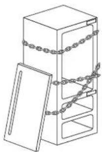
Line drawing of a cabinet with chains attached, no text or symbols presentIf this appliance is replacing an existing appliance which must be removed or disposed of, make sure that it does not become a dangerous trap for children by cutting its power supply cable and rendering it impossible to close the door.
Use the same caution at the end of the lifespan of the new appliance.

Important!
Dimensions in parentheses are in inches.
Weights in parentheses are in pounds.
Temperatures in parentheses are in Fahrenheit degrees.
2.1 Appliance features and installation requirements
| AppliancedimensionsIntegrated | Series 449w: 449 mm (17 5/8")h: 2050 mm (80 3/4")d: 615 mm (24 1/4") OFSeries 599w: 599 mm (23 5/8")h: 2050 mm (80 3/4")d: 610 mm (24") 1T/0T/0Hd: 615 mm (24 1/4") OFSeries 749w: 749 mm (29 1/2")h: 2050 mm (80 3/4")d: 610 mm (24") 1T/0T/0Hd: 615 mm (24 1/4") OFSeries 899w: 899 mm (35 3/8")h: 2050 mm (80 3/4")d: 610 mm (24") 1T/0T/0Hd: 615 mm (24 1/4") OF |
| AppliancedimensionsClassic | Series 449w: 449 mm (17 5/8")h: 2050 mm (80 3/4")d: 640 mm (25 1/4") OFSeries 599w: 599 mm (23 5/8")h: 2050 mm (80 3/4")d: 635 mm (25") 1T/0T/0Hd: 640 mm (25 1/4") OFSeries 749w: 749 mm (29 1/2")h: 2050 mm (80 3/4")d: 635 mm (25") 1T/0T/0Hd: 640 mm (25 1/4") OFSeries 899w: 899 mm (35 3/8")h: 2050 mm (80 3/4")d: 635 mm (25") 1T/0T/0Hd: 640 mm (25 1/4") OF |
| AppliancedimensionsX-Pro / Country | Series 449w: 449 mm (17 5/8")h: 2120 mm (83 1/2")d: 640 mm (25 1/4") OFSeries 599w: 599 mm (23 5/8")h: 2120 mm (83 1/2")d: 635 mm (25") 1T/0T/0Hd: 640 mm (25 1/4") OFSeries 749w: 749 mm (29 1/2")h: 2120 mm (83 1/2")d: 635 mm (25") 1T/0T/0Hd: 640 mm (25 1/4") OFSeries 899w: 899 mm (35 3/8")h: 2120 mm (83 1/2")d: 635 mm (25") 1T/0T/0Hd: 640 mm (25 1/4") OF |
| AppliancedimensionsBrilliance-Integrated | Series 599w: 599 mm (23 5/8")h: 2050 mm (80 3/4"d: 610 mm (24")Series 749w: 749 mm (29 1/2")h: 2050 mm (80 3/4"d: 610 mm (24")Series 899w: 899 mm (35 3/8")h: 2050 mm (80 3/4"d: 610 mm (24") |
| AppliancedimensionsBrilliance-Classic | Series 599w: 599 mm (23 5/8")h: 2050 mm (80 3/4"d: 635 mm (25")Series 749w: 749 mm (29 1/2")h: 2050 mm (80 3/4"d: 635 mm (25")Series 899w: 899 mm (35 3/8")h: 2050 mm (80 3/4"d: 635 mm (25") |
| AppliancedimensionsIntegrated / Classic | Series 449w: 650 mm (25 5/8")h: 2210 mm (87"d: 800 mm (31 1/2")Series 599w: 650 mm (25 5/8")h: 2210 mm (87"d: 800 mm (31 1/2")Series 749w: 800 mm (31 1/2")h: 2210 mm (87"d: 800 mm (31 1/2")Series 899w: 950 mm (37 3/8")h: 2210 mm (87"d: 800 mm (31 1/2") |
| AppliancedimensionsX-Pro / Country/Brilliance | Series 449w: 650 mm (25 5/8")h: 2260 mm (89"d: 800 mm (31 1/2")Series 599w: 650 mm (25 5/8")h: 2260 mm (89"d: 800 mm (31 1/2")Series 749w: 800 mm (31 1/2")h: 2260 mm (89"d: 800 mm (31 1/2")Series 899w: 950 mm (37 3/8")h: 2260 mm (89"d: 800 mm (31 1/2") |
| Weight with packaging | Series 449up to 170 kg (375 lb)Series 599up to 200 kg (441 lb)Series 749up to 220 kg (485 lb)Series 899up to 240 kg (529 lb) |
| Voltage Europe Version:AC 220-240V 50 HzNorth America Version:110V 60Hz | |
| Power supply cable | Europe Version:Schuko 16 A plugNorth America Version:15 A |
| Potable water supply pressure | from 0.05 MPa to 0.5 MPa(0.5 Bar - 5 Bar) |
| Water supply tube - n°2 fittings 3/4" to 1/4"-mt 5 of alimentary watertube 1/4"-n°3 90° fittings 1/4"-n°1 water filter support(provided only with OFZ models) | |
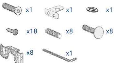
| Provided installation accessories | - Customized panelsmounting Kit-Anti-tipping Kit (B04000200)-Lateral connecting kit(KCLIT/KCLIH)-4 mm (1/8") allen wrench |
| Additional equipment necessary | - Phillips head screwdriver-wood and percussion drill-2.5 mm (1/8") bit for wood-8 mm (3/8") bit for walls-17 mm (3/4") wrench |
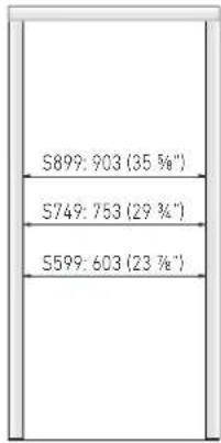
2.2 Installation niche features: Integrated Series, 1T - 0T - 0H Models
A - area to be left clear for the anti-tipping brackets
E - area to be left clear for the power supply cable
W - and water supply hose
Minimum Niche Height
2064 mm (81 1/4")
| STANDARD NICHE WIDTH | MINIMUM NICHE WIDTH WITH PORTAL |
| S899: 900 (35 1/2") S899: 903 (35 3/8") | |
| S749: 750 (29 5/8") S749: 753 (29 3/4") | |
| S599: 600 (23 3/4") S599: 603 (23 7/8") | |
Minimum Niche Depth
650 mm (25 5/8")
Door Swing Clearance
S899: 1485 mm (58 1/2")
S749: 1335 mm (52 5/8")
S599: 1185 mm (46 5/8")
Door Opening Angle
105°
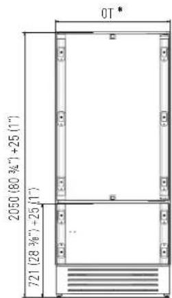
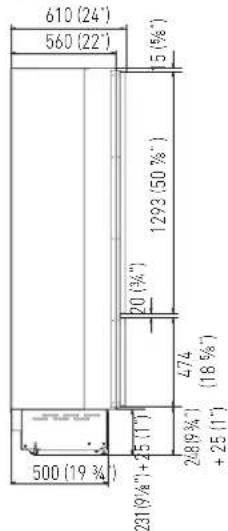
Width \*
Depth with door (without panel)
610 mm (24")
Minimum distance from the wall (hinge side) with door at 105° and 90°, with 18mm (3/4") panel and handle h=58mm (2 1/4").

Dimensions in parentheses are in inches.
2.3 Installation niche features: Integrated Series, OF Column Models
A - area to be left clear for the anti-tipping brackets
E - area to be left clear for the power supply cable
W - and water supply hose
Minimum Niche Height
2064 mm (81 1/4")
| STANDARD NICHE WIDTH | MINIMUM NICHE WIDTH WITH PORTAL |
| S899: 900 (35 1/2") S899: | 903 (35 3/8") |
| S749: 750 (29 5/8") S749: | 753 (29 3/4") |
| S599: 600 (23 3/4") S599: | 603 (23 7/8") |
| S449: 450 (17 3/4") S449: | 453 (17 7/8") |
Minimum Niche Depth
650 mm (25 5/8")
Door Swing Clearance
Depth with door (without panel)
615 mm (24 1/4")
Minimum distance from the wall (hinge side) with door at 105° and 90°, with 18mm (3/4") panel and handle h=58mm (2 1/4").
S899: 160 mm (6 1/4")
S749: 125 mm (5")
S599: 90 mm (3 1/2")
S449: 50 mm (1 7/8")


Dimensions in parentheses are in inches.

2.4 Installation niche features: Classic Series, 1T - 0T - 0H Models
A - area to be left clear for the anti-tipping brackets
E - area to be left clear for the power supply cable
W - and water supply hose
Minimum Niche Height
2064 mm (81 1/4")
Minimum Niche Width
KS899: 900 mm (35 1/2")
KS749: 750 mm (29 5/8")
KS599: 600 mm (23 3/4")
Minimum Niche Depth
650 mm (25 5/8")
Door Swing Clearance
KS899: 1475 mm (58 1/8")
KS749: 1325 mm (52 1/8")
KS599: 1175 mm (46 1/4")
Door Opening Angle
105°
Width \*
KS899: 899 mm (35 3/8")
KS749: 749 mm (29 1/2")
KS599: 599 mm (23 5/8")
Height
2050 mm (80 3/4") + 25 mm (1")
Depth with door
635 mm (25")
Minimum distance from the wall (hinge side) with door at 105° and 90°.
KS899: 230 mm (9")
KS749: 195 mm (7 3/4")
KS599: 160 mm (6 1/4")

Dimensions in parentheses are in inches.


2.5 Installation niche features: Classic Series, OF Column Models
A - area to be left clear for the anti-tipping brackets
E - area to be left clear for the power supply cable
W - and water supply hose
Minimum Niche Height
2064 mm (81 1/4")
Minimum Niche Width
KS899: 900 mm (35 1/2")
KS749: 750 mm (29 5/8")
KS599: 600 mm (23 3/4")
KS449: 450 mm (17 3/4")
Minimum Niche Depth
650 mm (25 5/8")
Door Swing Clearance
KS899: 1480 mm (58 1/4")
KS749: 1330 mm (52 3/8")
KS599: 1180 mm (46 1/2")
KS449: 1030 mm (40 1/2")
Door Opening Angle
105°
Width \*
KS899: 899 mm (35 3/8")
KS749: 749 mm (29 1/2")
KS599: 599 mm (23 5/8")
KS449: 449 mm (17 5/8")
Height
2050 mm (80 3/4") + 25 mm (1")
Depth with door
640 mm (25 1/4")
Minimum distance from the wall (hinge side) with door at 105° and 90°.
KS899: 230 mm (9")
KS749: 195 mm (7 3/4")
KS599: 160 mm (6 1/4")
KS449: 125 mm (4 7/8")

Dimensions in parentheses are in inches.
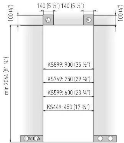


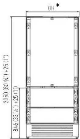
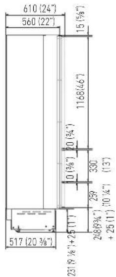
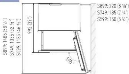
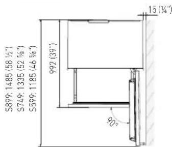
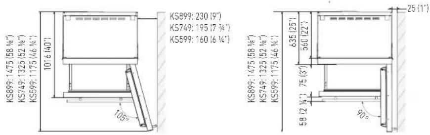
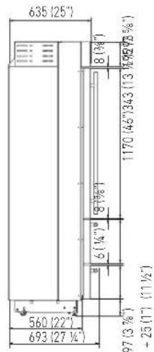
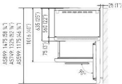
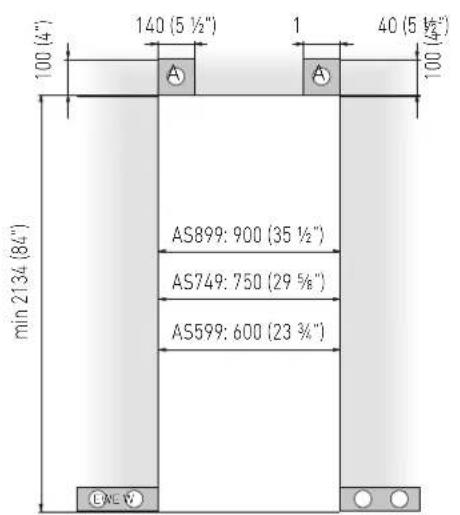
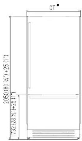
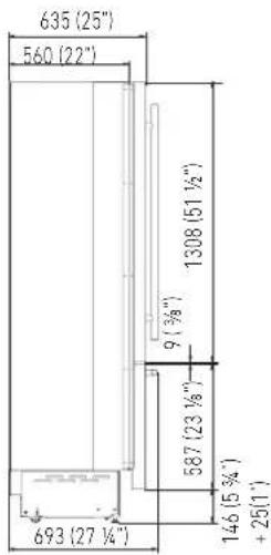
2.6 Installation niche features: X-Pro Series
A - area to be left clear for the anti-tipping brackets
E - area to be left clear for the power supply cable
W - and water supply hose
Minimum Niche Height
2134 mm (84")
Minimum Niche Width
XS899: 900 mm (35 1/2")
XS749: 750 mm (29 5/8")
XS599: 600 mm (23 3/4")
Door Swing Clearance
XS899: 1475 mm (58 1/8")
XS749: 1325 mm (52 1/8")
XS599: 1175 mm (46 1/4")
Door Opening Angle
105°
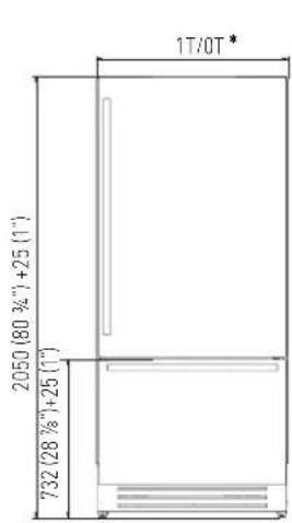
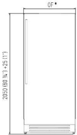
Width
XS899: 899 mm (35 3/8")
XS749: 749 mm (29 1/2")
XS599: 599 mm (23 5/8")
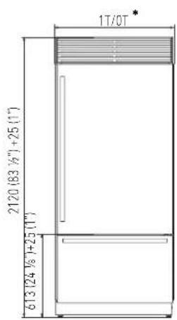
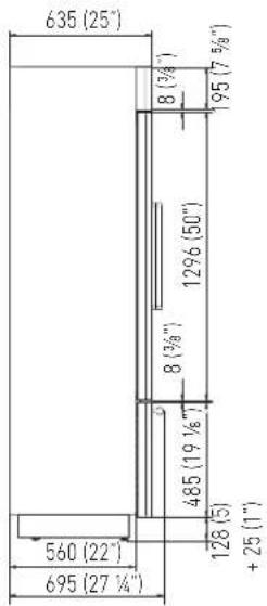
Height
2120 mm (83 1/2") + 25 mm (1")
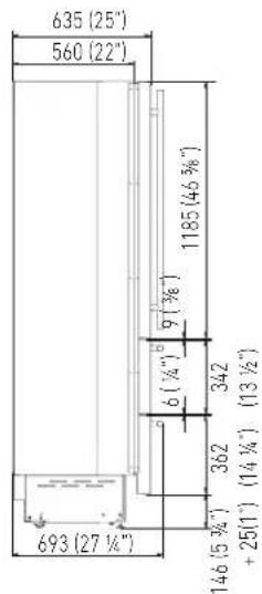
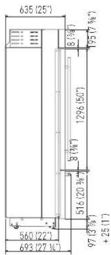
Depth with door
635 mm (25")
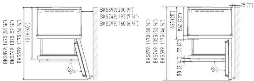
Minimum distance from the wall (hinge side) with door at 105° and 90°.
XS899: 230 mm (9")
XS749: 195 mm (7 3/4")
XS599: 160 mm (6 1/4")

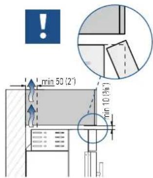
Important!
If the units are to be installed inside a niche or within an enclosed structure, it is necessary to design a ventilation shaft at the back of the niche to assure proper ventilation at the back of the unit.

Dimensions in parentheses are in inches.


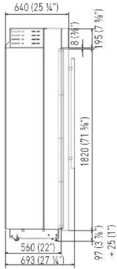
2.7 Installation niche features: X-Pro Series: - OF Column Models
A - area to be left clear for the anti-tipping brackets
E - area to be left clear for the power supply cable
W - and water supply hose
Minimum Niche Height
2134 mm (84")
Minimum Niche Width
XS899: 900 mm (35 1/2")
XS749: 750 mm (29 5/8")
XS599: 600 mm (23 3/4")
XS449: 450 mm (17 3/4")
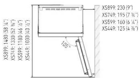
Door Swing Clearance
XS899: 1480 mm (58 1/4")
XS749: 1330 mm (52 3/8")
XS599: 1180 mm (46 1/2")
XS449: 1030 mm (40 1/2")
Door Opening Angle
105°
Width
XS899: 899 mm (35 3/8")
XS749: 749 mm (29 1/2")
XS599: 599 mm (23 5/8")
XS449: 449 mm (17 5/8")
Height
2120 mm (83 1/2") + 25 mm (1")
Depth with door
640 mm (25 1/4")
Minimum distance from the wall (hinge side) with door at 105° and 90°.
XS899: 230 mm (9")
XS749: 195 mm (7 3/4")
XS599: 160 mm (6 1/4")
XS449: 125 mm (4 7/8")

Important!
If the units are to be installed inside a niche or within an enclosed structure, it is necessary to design a ventilation shaft at the back of the niche to assure proper ventilation at the back of the unit.

Dimensions in parentheses are in inches.


2.8 Installation niche features: Country Series
A - area to be left clear for the anti-tipping brackets
E - area to be left clear for the power supply cable
W - and water supply hose
Minimum Niche Height
2134 mm (84")
Minimum Niche Width
AS899: 900 mm (35 1/2")
AS749: 750 mm (29 5/8")
AS599: 600 mm (23 3/4")
Door Swing Clearance
AS899: 1475 mm (58 1/8")
AS749: 1325 mm (52 1/8")
AS599: 1175 mm (46 1/4")
Door Opening Angle
105°
Width
AS899: 887 mm (35")
AS749: 737 mm (29")
AS599: 587 mm (23 1/8")
Height
2120 mm (83 1/2") + 25 mm (1")
Depth with door
635 mm (25")
Minimum distance from the wall (hinge side) with door at 105° and 90°.
AS899: 230 mm (9")
AS749: 195 mm (7 3/4")
AS599: 160 mm (6 1/4")

Important!
If the units are to be installed inside a niche or within an enclosed structure, it is necessary to design a ventilation shaft at the back of the niche to assure proper ventilation at the back of the unit.

Dimensions in parentheses are in inches.


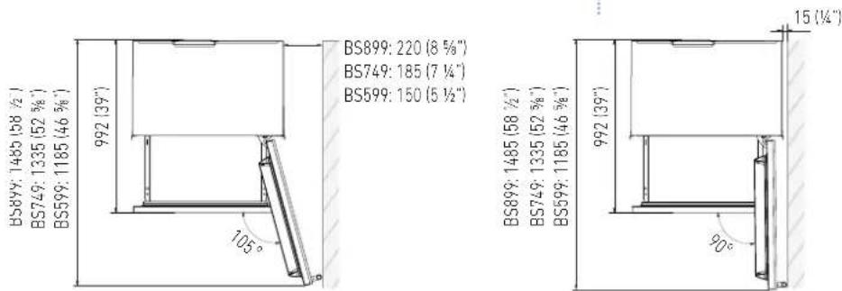
2.9 Installation niche features: Brilliance-Integrated Series
A - area to be left clear for the anti-tipping brackets
E - area to be left clear for the power supply cable
W - and water supply hose
Minimum Niche Height
2064 mm (81 1/4")
| STANDARD NICHE WIDTH | MINIMUM NICHE WIDTH WITH PORTAL |
| BS899: 900 (35 1/2") BS899: 903 (35 3/8") | |
| BS749: 750 (29 5/8") BS749: 753 (29 3/4") | |
| BS599: 600 (23 3/4") BS599: 603 (23 7/8") | |
Minimum Niche Depth
650 mm (25 5/8")
Door Swing Clearance
BS899: 1485 mm (58 1/2")
BS749: 1335 mm (52 5/8")
BS599: 1185 mm (46 5/8")
Door Opening Angle
105°
Width \*
BS899: 899 mm (35 3/8")
BS749: 749 mm (29 1/2")
BS599: 599 mm (23 5/8")
Height
2050 mm (80 3/4") + 25 mm (1")
Depth with door (without panel)
610 mm (24")
Minimum distance from the wall (hinge side) with door at 105° and 90°, with 18mm (3/4") panel and handle h=58mm (2 1/4").
BS899: 220 mm (8 5/8")
BS749: 185 mm (7 1/4")
BS599: 150 mm (5 1/2")

Dimensions in parentheses are in inches.

2.10 Installation niche features: Brilliance-Classic Series
A - area to be left clear for the anti-tipping brackets
E - area to be left clear for the power supply cable
W - and water supply hose
Minimum Niche Height
2064 mm (81 1/4")
Minimum Niche Width
BKS899: 900 mm (35 1/2")
BKS749: 750 mm (29 5/8")
BKS599: 600 mm (23 3/4")
Minimum Niche Depth
650 mm (25 5/8")
Door Swing Clearance
BKS899: 1475 mm (58 1/8")
BKS749: 1325 mm (52 1/8")
BKS599: 599 mm (23 5/8")
Height
2050 mm (80 3/4") + 25 mm (1")
Depth with door
635 mm (25")
Minimum distance from the wall (hinge side) with door at 105° and 90°.
BKS899: 230 mm (9")
BKS749: 195 mm (7 3/4")
BKS599: 160 mm (6 1/4")

Dimensions in parentheses are in inches.

3.1 Transport to installation site and unpacking

The appliance is very heavy. Take maximum care during handling to avoid injury.

The appliance should always be transported in an erect position. Avoid at all costs leaning it on its front side.
Since this is a large and heavy appliance, before transporting the appliance, check the access to the location where it will be installed (door size, manoeuvring space in stairwells, etc.).
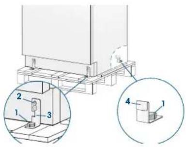
The appliance is attached to the base of the packaging (pallet) through four bolts which can be removed using a 17 mm (3/4") wrench.
It is recommended to use a manual transporting device to move the appliance to the installation site, and only at this point to remove the base of the packaging.
The appliance should always be transported in an erect position.
If this is not possible, transport the appliance laying on its rear side.
Once at the installation site, the appliance, which is equipped with four wheels, can be taken off the pallet and positioned in the installation area.
Operate as follows:
Take off the four boltshsecuring the appliance to the pallet by means of a 17 mm (3/4") open spanner.
Remove the fixing brackets [3] and [4].
To remove the front fixing bracket [3], unscrew for one or two turns the rear wheel adjusting bolt [2] by means of a 13 mm (1/2") box spanner, avoiding too much strenght while thickening the nut, which could damage the leveling feet adjusting system.
From the back of the unit and by means of a suitable, high duty hand trolley, take off the appliance and place it on the floor.
Be very careful to avoid any damage to floors. Delicate floors should be protected with plywood, hard cardboard or similar material panels.
3.2 Electrical and Water connection

The Built-in Fhiaba filter cannot make it safe to drink any water which is not suitable for human consumption.

The appliance should be connected only to a drinkable water supply system.

Do not use extension cords or adapters. Once the appliance has been connected to the water system, turn the Ice Maker off (touch the button ▲ on control panel to switch it off) before the main water is shut off.
natural_image
Pure electrical circuit lines without any symbolsA Schuko 16 A socket with an efficient grounding should be made available for the electrical mains connection, as well as an omnipolar switch which can easily be reached when the appliance is installed.
To connect to the water supply system (for appliances equipped with ice makers) a tap with a male 3/4" connection should be provided, which must also be easily accessible once the appliance is installed.
The appliance is provided with a water supply hose and seal kit which is suitable for high water pressure and complies the Food Regulations.
The water filter cartridge, which is provided with the appliance, should be installed according to the accompanying instructions.
Use only the new hose and the new gaskets which are supplied with the appliance. Discard any hose and gasket which may have already been installed.
Electrical cord length: 2,0 mt (78 3/4")
Water connection line length: 2,5 mt (98 3/8")
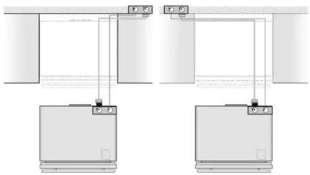
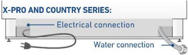
ELECTRICAL AND WATER SUPPLY BEHIND THE UNIT
INTEGRATED AND CLASSIC SERIES:
natural_image
Technical line drawing of a mechanical assembly with labeled components (E and W), no readable text or symbols present.X-PRO AND COUNTRY SERIES:

natural_image
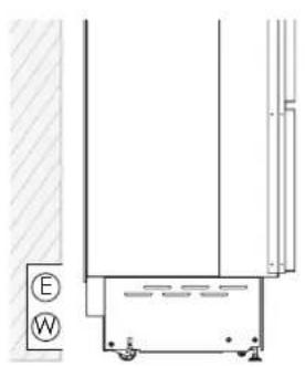
Technical line drawing of a door frame structure with no visible text or symbolsINTEGRATED AND CLASSIC SERIES:

Back of appliance
Operate as follows:
Unwind the electric cable and connect it directly to the wall socket.
Make sure the appliance is in the Stand-by condition and that all lights are off; should it be not so press the Unit button ⏻ to switch it off.
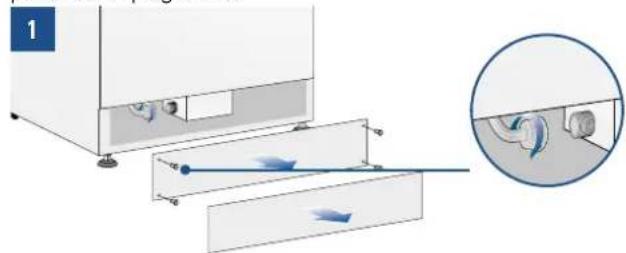
natural_image
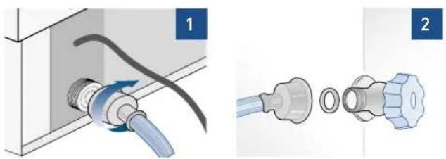
Two-step diagram showing a pipe fitting with a blue plastic connector and a separate close-up of the internal components (no text or symbols)Fit one end of the water hose onto the connector at the appliance's back, using the supplied 3/4" fitting [1].
Fit the other end of the hose to the water tap, using the supplied 3/4" fitting [2].
On OFZ models only, install the water filter support outside the appliance, using the fittings supplied (see page 49).
Back of appliance
Operate as follows:
Unwind the electric cable and connect it directly to the wall socket.
Make sure the appliance is in the Stand-by condition and that all lights are off; should it be not so press the Unit button ⏻ to switch it off.
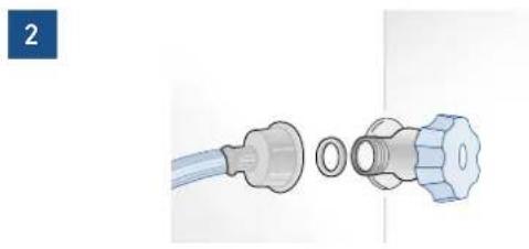
Connect the water pipe to the threaded connection located at the base of the appliance [1], using the 3/4" fitting supplied.
Connect the hose to the tap using the 3/4" fitting supplied [2].
Only on 0FZ models, install the water filter support externally to the appliance, using the fittings supplied (see page 49).
natural_image
Diagram showing a mechanical device with internal components and fluid flow direction, including a magnified inset of the pipe connection (no text or symbols)Front of appliance
natural_image
Diagram of a medical or laboratory device with two connected parts, one showing a bulb and the other a valve (no text or symbols present)3.3 Levelling
Adjust the appliance level by means of the front levelling feet and the rear adjustable wheels.
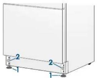
Operate as follows:
After removing the bottom plinth or grille (it is kept in position by magnets), adjust the height of the levelling feet [1] by means of a 17 mm (3/4") open spanner.
Then adjust the height of the rear wheels by turning the front adjusting bolts [2] clockwise or anticlockwise as it may be required.
Remount the bottom plinth or grille.
INTEGRATED SERIES
4.1 Decorative door and bottom-drawer panels layout
The dimensions of the panels are indicated in the table and drawings on next pages.
Nevertheless, according to the requirements for aligning with other kitchen structures, the door panel can be higher than the upper edge of the refrigerator door, and the drawer panel can be lower than the edge of the drawer.
The panels must be mounted using special braces which attach to adjustable devices provided on the door and drawer and with brackets that anchor and adjust the panel's vertical direction. Braces, brackets and fixing screws are provided with the appliance and must be applied to the panel as indicated.
Operate as follows:
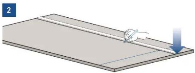
To prepare the panels to be mounted on the appliance, follow these steps, working on the back of the panel.
Door Panel
Trace, a line dividing the panel width in half [1].

natural_image
Simple 3D illustration of a flat surface with a small animal-like shape on top, no text or symbols present.Starting form the Bottom edge of the panel, mark the positioning of the brackets [2].
natural_image
Illustration of a mouse pulling a thin rod on a flat surface with a blue downward arrow (no text or symbols)Following the corresponding table, mark the external and then the internal hole [3].

natural_image
Illustration of a hand using a tool to cut or mark a flat surface, no text or symbols presentPosition the brackets on each set of marks to make sure they are aligned [4], then drill holes through the panel (pay close attention to the panel's thickness) [5].
natural_image
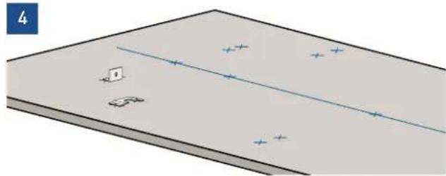
Diagram of a rectangular plate with a diagonal line and scattered blue cross marks, no text or symbols present.Screw the brackets in place [6].

Drawer Panel
When preparing the Drawer Panel, follow the same instructions as per the door panel, but make sure measurements are taken starting from the top edge [7].
The support bracket faces the opposite way [8] (note imgs 4 and 8).

natural_image
Illustration of a tool on a workbench with two screwdrivers and a highlighted U-shaped component (no text or symbols)4.2 Decorative panels layout for Fridge with one Bottom-Drawer (1T/0T)
natural_image
Technical line drawing of a two-cell refrigerator with front and back panels (no text or symbols)| SERIES 899 SERIES 749 SERIES 599 | ||
| A 897 (35 1/4") 747 (29 3/8") 597 (23 1/2") | ||
| B 4 7 (16 3/8") 342 (13 1/2") 276,5 (10 7/8") | ||
| C 354,5 (14") 279,5 (11") 203,5 (8") | ||
natural_image
Pure mechanical component diagram without any text, numbers, or symbols
natural_image
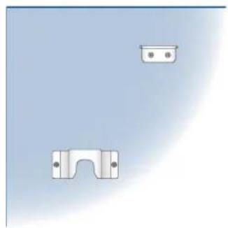
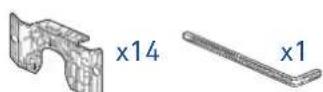
Two metallic bracket components with mounting holes, one upright and one flat, against a plain light blue background (no text or symbols)B04000100 Built-in kit

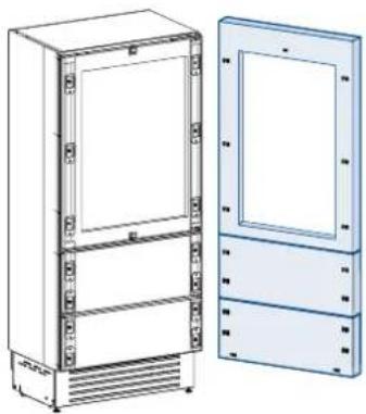
4.3 Decorative panels layout for Fridge with two Bottom-Drawers (0H)
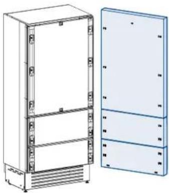
natural_image
Technical line drawing of a multi-tiered refrigerator unit with front and side views (no text or symbols)| SERIES 899 SERIES 749 | ||
| A | 897 (35 1/4") 747 | 29 3/8") |
| B | 417 (16 3/8") 342 | 13 1/2") |
| C | 354,5 (14") 279,5 (11") | |
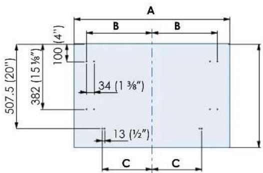
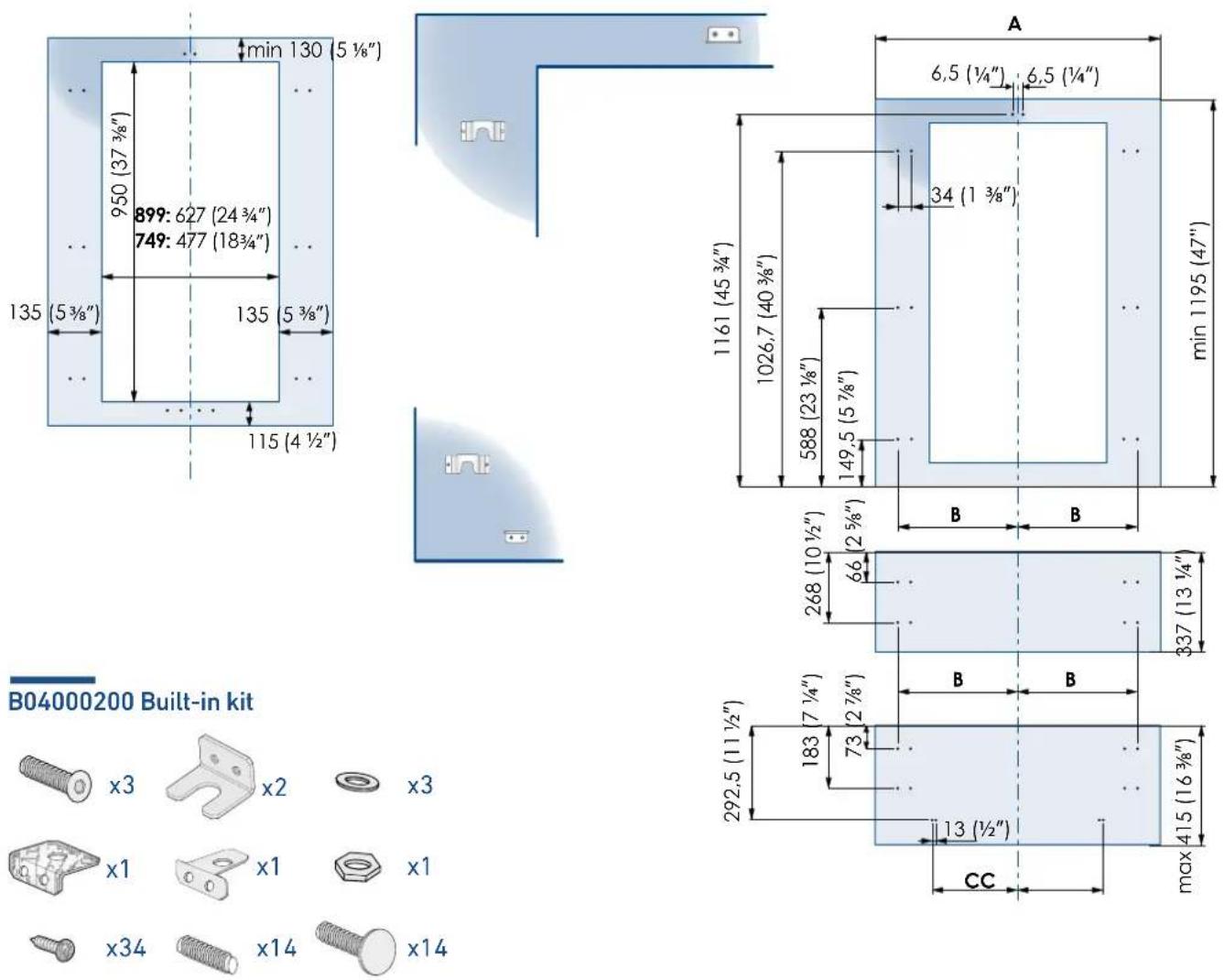
Holes positions:
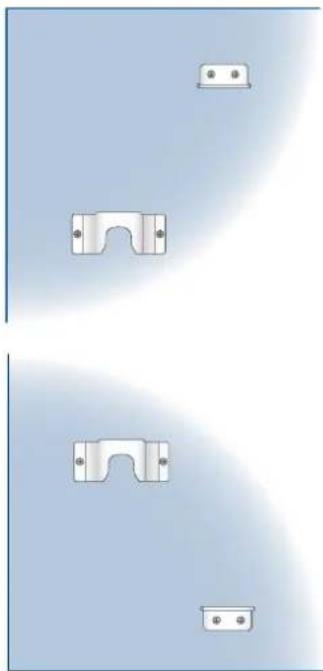
natural_image
Pure diagram of mechanical parts with mounting holes and brackets, no text or symbols presentB04000200 Built-in kit
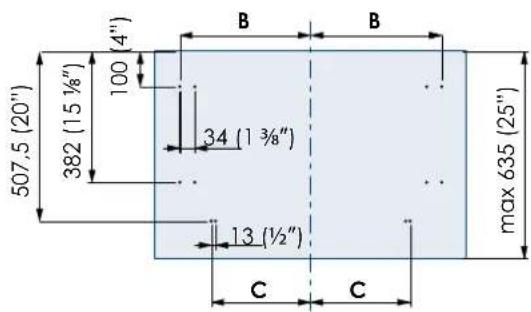
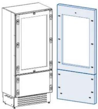
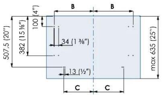
4.4 Decorative panels layout
for Fridge with glass door and one Bottom-Drawer (1T/0T)
natural_image
Technical line drawing of two rectangular electronic cabinets with ventilation grilles (no text or symbols)| SERIES 899 SERIES 749 SERIES 599 | ||
| A 897 (35 1/4") 747 (29 3/8") 597 (23 1/2") | ||
| B 4 7 (16 3/8") 342 (13 1/2") 276,5 (10 7/8") | ||
| C 354,5 (14") 279,5 (11") 203,5 (8") | ||
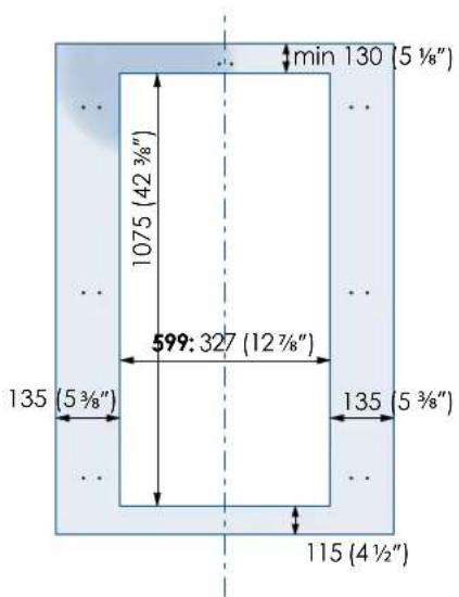
Holes positions: Door window dimen:

B04000200 Built-in kit
4.5 Decorative panels layout for Fridge with glass door Brilliance
natural_image
Technical line drawing of a two-door refrigerator with front and side views (no text or symbols)| SERIES 599 | |
| A 597 (23 1/2") | |
| B 276,5 (10 7/8") | |
| C 203,5 (8") | |
Door window dimensions: Holes positions:

B04000100 Built-in kit

4.6 Decorative panels layout for Fridge with glass door and two Bottom-Drawers (OH)
natural_image
Technical line drawing of a refrigerator and cabinet (no text or symbols)| SERIES 899 SERIES 749 | |
| A 897 (35 1/4") 747 | 29 3/8") |
| B 4 7 (16 3/8") 342 | 13 1/2") |
| C 354,5 (14") 279,5 | (11") |
Holes positions: Door window dimens
4.7 Decorative panels layout for Fridge Column (OF)
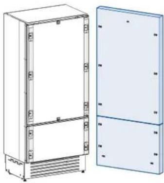
natural_image
Technical illustration of a rectangular enclosure with internal components and a separate panel on the right (no text or symbols)| SERIES 899 SERIES 749 SERIES 599 SERIES 449 | ||
| A | 897 (35 1/4") 747 | 29 3/8") 597 (23 1/2") 447 (17 5/8") |
| B | 418 (16 1/2") 343 | 13 1/2") 276,5 (10 7/8") 200 (7 7/8") |

natural_image
Two metallic bracket components with mounting holes, one plain and one with a curved cutout (no text or symbols)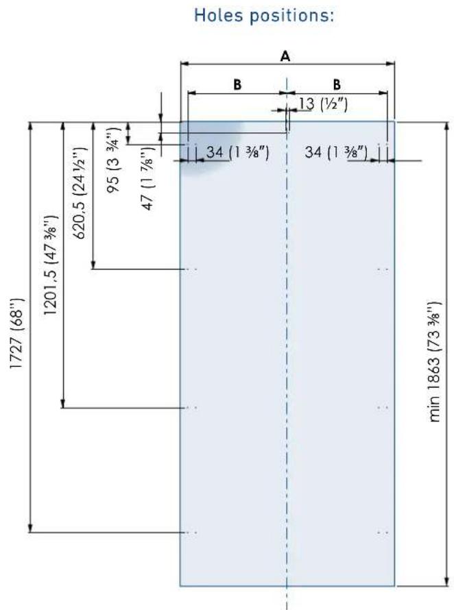
B04009000 Built-in kit
4.8 Decorative panels layout for Fridge column with glass door (OF)

natural_image
Technical illustration of a rectangular enclosure with internal panels and mounting holes, shown from two different angles (no text or symbols present)| SERIES 899 SERIES 749 SERIES 599 SERIES 449 | |||
| A | 897 (35 1/4") 747 | (29 3/8") 597 (23 | 1/2") 447 (17 19/32") |
| B | 48 (16 1/2") 343 | (13 1/2") 276,5 | (10 7/8") 200 (7 7/8") |
Door window dimensions: Holes positions:


B04009000 Built-in kit

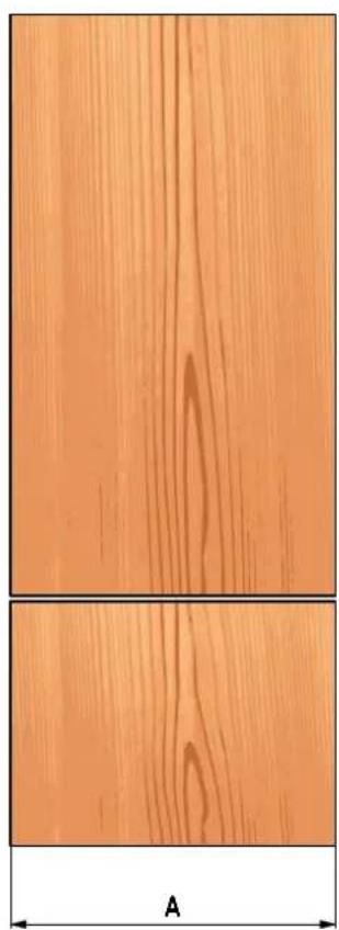
4.9 Panels Dimensions One Bottom - Drawer (1T/0T models)
Panels with width ranging between 18 mm (3/4 in) and 28 mm (1 1/8 in).
Door panels with weight max of 23 kg (51 lb) and drawer panels with weight max of 11 kg (25 lb).
Provide installation of decorative panels during installation of the unit.
| SERIES | DOR/DRAWER WIDTH A DOOR CUTOUT WIDTH B |
| 899 897 | (35 1/4") 627 (24 3/4") |
| 749 747 | (29 3/8") 477 (18 3/4") |
| 599 597 | (23 1/2") 327 (12 7/8") |

natural_image
Two wooden panels with grain patterns, labeled 'A' at the bottom (no text or symbols on panels)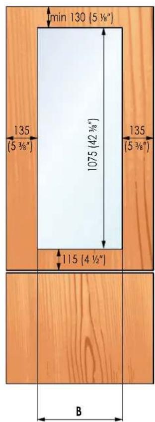
4.10 Panels DimensionsTwo Bottom - Drawers (OH models)
Panels with width ranging between 18 mm (3/4 in) and 28 mm (1 1/8 in).
Door panels with weight max of 23 kg (51 lb) and drawer panels with weight max of 11 kg (25 lb).
Provide installation of decorative panels during installation of the unit.
| SERIES | DOR/DRAWER WIDTH A DOOR CUTOUT WIDTH B |
| 899 897 | (35 1/4") 627 (24 3/4") |
| 749 747 | (29 3/8") 477 (18 3/4") |
| 599 597 | (23 1/2") 327 (12 7/8") |

natural_image
Three wooden panel panels showing different grain patterns, with a labeled dimension 'A' at the bottom (no text or symbols on panels)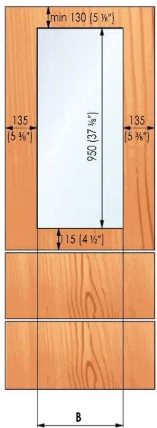
4.11 Panels Dimensions Column Models (OF models)
Panels with width ranging between 18 mm (3/4 in) and 28 mm (1 1/8 in).
Door panels with weight max of 34 kg (75 lb).
Provide installation of decorative panels during installation of the unit.
| SERIES | DOR/DRAWER WIDTH A DOOR CUTOUT WIDTH B |
| 899 897 | (35 1/4") 627 (24 3/4") |
| 749 747 | (29 3/8") 477 (18 3/4") |
| 599 597 | (23 1/2") 327 (12 7/8") |
| 449 447 | (17 5/8") 177 (6 7/8") |

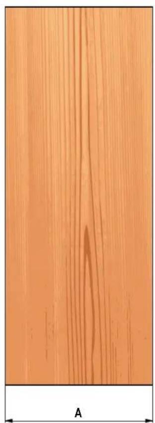
natural_image
Close-up of a wooden surface with visible grain patterns and a labeled dimension 'A' (no text or symbols beyond the label)
4.12 Mounting the handles

Handles will have to be mounted on the panels before they are applied to the fridge.
Operate as follows:
Drill two holes on the back of the panels according to the table below [1].
1

natural_image
3D diagram of a cabinet with an open door and a magnified inset showing a detail (no text or symbols)Place the handle on top of the holes and insert the screws through the panel and into the handle support [2].
2

natural_image
Technical illustration of a cabinet with an open door and a close-up view showing a vertical component (no text or symbols)
| ø30 mm | HANDLE PRODUCT CODE | |||
| HV H08 | H07 H05 | |||
| Lenght A | 1104 mm(43 1/2") | 794 mm(31 1/4") | 644 mm(25 3/8") | 494 mm(19 5/8") |
| Distance between fixing points X | 900 mm(35 1/2") | 480 mm(18 7/8") | 490 mm(19 1/4") | 340 mm(13 3/8") |
| Series | 899749599449 | 899 749 | 599 | |
| ø18 mm | HANDLE PRODUCT CODE | |||
| HCV HC8 | HC7 HC5 | |||
| Lenght A | 794 mm(43 1/2") | 794 mm(31 1/4") | 644 mm(25 3/8") | 494 mm(19 5/8") |
| Distance between fixing points X | 480 mm(18 7/8") | 480 mm(18 7/8") | 490 mm(19 1/4") | 340 mm(13 3/8") |
| Series | 899749599449 | 899 749 | 599 | |
4.13 Mounting panels to the door and the drawer

Once all brackets and small brackets have been applied to the panels, you can begin installing the bottom drawer.
Operate as follows:
Partially tighten the screw to the fixing [1].
1
natural_image
Diagram showing a screw being inserted into a bracket with directional arrows indicating motion (no text or symbols)Hook the bottom drawer panel starting from the fixings on the bottom [2].
2

flowchart
graph TD
    A["Device 1"] -->|Bidirectional Arrow| B["Device 2"]
    B -->|Transliver| A
    C["Device 3"] -->|Transliver| B
    D["Device 4"] -->|Transliver| B
    E["Device 5"] -->|Transliver| B
    F["Device 6"] -->|Transliver| B
It is now possible to align panels to adjacent cabinets in height using the lower alignment brackets, [3] tightening or untightening the screws into position as needed. With the screw slightly tightened, move the panel sideways to align it to the other panels on the unit or other adjacent structures.
3
natural_image
Diagram of a mechanical or fluidic device with directional arrows indicating flow or movement (no text or symbols present)Depth alignment: working from the inside of the drawer, after lifting up the magnetic seal, adjust the panel position so it is closer to or further away from the door using the holes [4] and then secure the panel using the holes [5].

Hook the panel to the fixing devices starting from the top aligning brackets [6].
6

natural_image
Technical diagram of a mechanical assembly with mounting holes and a magnified inset showing detail (no text or symbols)At this point, alignment between the panel and adjacent cabinets can be adjusted using the alignment brackets and small brackets [7] and [8].
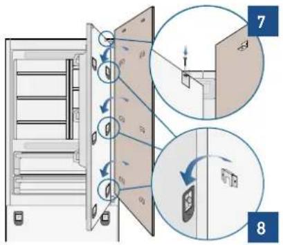
Vertical alignment: tighten or loosen the screw in the brackets to raise or lower the panel [9].
9
natural_image
Diagram of a faucet assembly with directional arrows indicating flow or movement (no text or symbols)Depth alignment: working from the inside of the door, after lifting up the magnetic seal, adjust the panel position so it is closer to or further away from the door using the holes [10] and then fix the panel in position using the holes [11].


Once the front panel has been adjusted, check that the gasket has been repositioned correctly to assure the door/drawer are closing correctly and avoid operational errors of the unit.
5.1 Built-in installation single appliance
For a built-in installation, to close gaps between the appliance and the adjacent cabinets, special side profiles and PVC covering frames are provided.
Operate as follows:
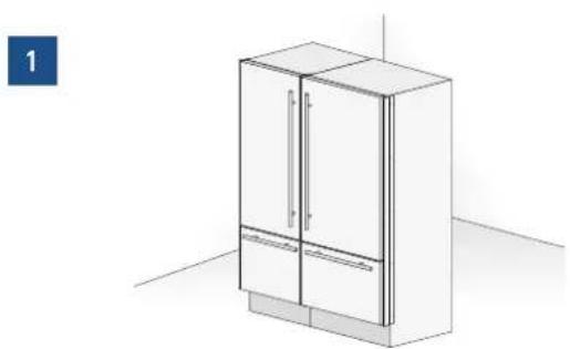
Push the appliance into the installation niche [1].
1
natural_image
Diagram of a refrigerator and cabinet with blue horizontal bars indicating internal components (no text or symbols)If the unit is to be installed inside a niche or within an enclosed structure, it is necessary to design a ventilation shaft at the back of the niche to assure proper ventilation at the back of the unit. A 5 mm gap is sufficient to prevent overheating. Always mount front panels on door and drawer before pushing the unit into its final position inside the niche or structure.
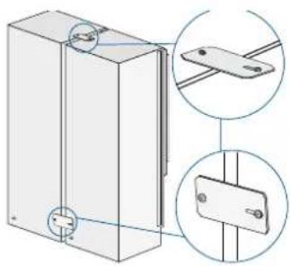
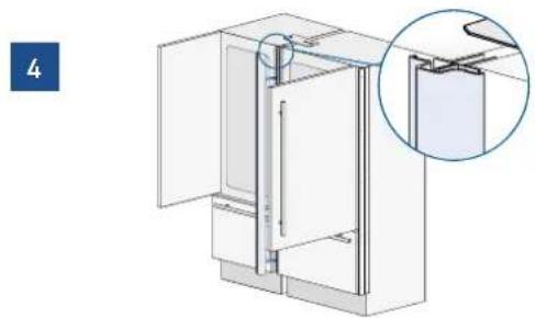
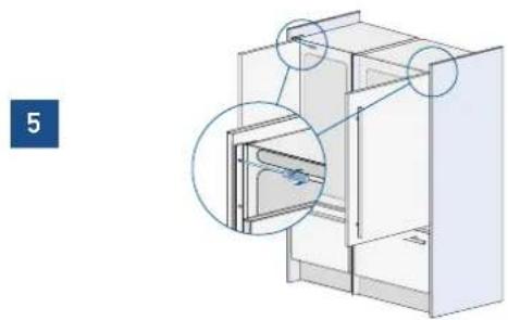
Secure the appliance to the adjacent cabinets by fixing to these the side profiles previously mounted on the appliance [2].
To make this operation easier keep the door and the drawer open.
Check the levelling of the appliance, adjusting its feet and wheels to correct it.
2

natural_image
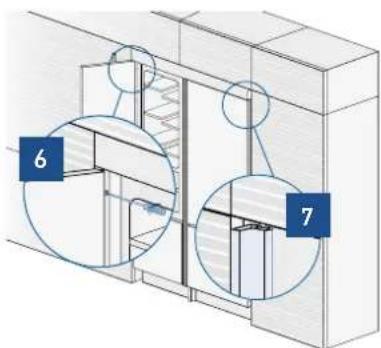
Technical diagram of a mechanical assembly with two circular insets showing close-ups of components (no text or symbols)Mount the profiles the covering frames: first insert them laterally and then push firmly until a "click" is heard [3].
3

natural_image
Technical diagram of a mechanical assembly with highlighted components (no text or symbols)Side profiles mounting:

A PVC connecting element, alternatively: C plastic connecting brackets B Alluminium frame
5.2 Built-in installation two or more appliances
Required accessories to be ordered separately:
Central connection Kit (KCC)

Special side profiles and PVC covering frames are provided for closing gaps between the appliance and the adjacent cabinets.
B04017900 Union kit

natural_image
Technical illustration of mechanical parts including a flange, cylindrical components, and a bracket (no text or symbols)Operate as follows:
Position the appliances in front of the installation area, leaving enough space to operate at their back [1].
1
natural_image
Architectural line drawing of a cabinet and adjacent wall (no text or symbols)Move at the back of the appliances to mount the joining brackets: fix on side of the top and lower brackets to one of the appliances and subsequently to the other [2].
2
natural_image
Technical illustration of a rectangular panel with mounting holes and two circular insets showing internal components (no text or symbols)Place the two units side by side and join them at the front attaching the profiles with the supplied screws [3].
natural_image
Diagram of a refrigerator interior showing door, front panel, and side door (no text or labels)Finish off by mounting the central cover frame onto the central profiles, by pushing it until a click is heard [4].
4

natural_image
Technical line drawing of a cabinet or enclosure with an inset close-up showing a detail (no text or symbols)Once completed the previous steps, push the units in their final position [5].
If the units are to be installed inside a niche or within an enclosed structure, it is necessary to design a ventilation shaft at the back of the niche to assure proper ventilation at the back of the unit of about 20mm. Always mount front panels on door and drawer before pushing the unit into its final position inside the niche or structure.
Check the levelling of the appliance, adjusting its feet and wheels to correct it.
Secure the appliance to the adjacent cabinets by fixing to these the side profiles [6]. To make this operation easier keep the door and the drawer open.
5
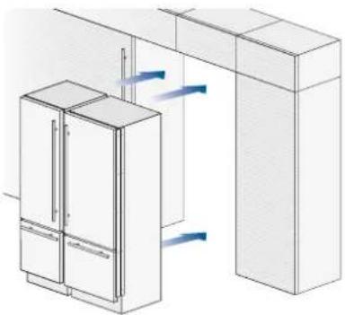
natural_image
Isometric line drawing of a refrigerator and adjacent kitchen cabinet with airflow arrows (no text or symbols)Mount the covering frames onto the profiles, first insert them laterally and then push firmly until a "click" is heard [7].
Side and central profiles mounting:
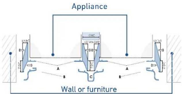
A - Side connection profile in PVC.
B - Aluminum cover frame
C - Central covering frame in aluminum
5.3 Free-standing installation two or more appliances
Required accessories to be ordered separately:
Central Connection Kit (KCC)
Freestanding Kit
Aluminium profiles can be used to close the spaces between the appliance and adjacent structures.
Operate as follows:
Position the appliances in front of the installation area, leaving enough space to operate at their back.
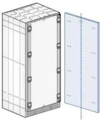
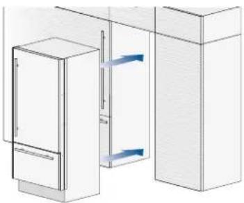
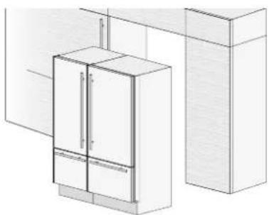
Peel off the self adhesive protection and apply the insulated anticondensation panel to the side of one appliance [1].
natural_image
Line drawing of a modern refrigerator cabinet with doors and drawers, shown in 3D perspective (no text or symbols)Move at the back of the appliances to mount the joining brackets: fix one side of the top and lower brackets to one of the appliances and subsequently to the other [2].

natural_image
Technical illustration of a mechanical assembly with two views of a bracket and mounting holes (no text or symbols)Place the two units side by side and join them at the front attaching the two profi les with the supplied screws [3].

natural_image
3D diagram of a refrigerator with open door and side panels, showing internal components (no text or symbols)Finish off by mounting the central cover frame onto the central profiles, by pushing it until a click is heard [4].
natural_image
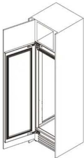
Technical illustration of a refrigerator with an inset close-up showing internal components (no text or symbols)Attach the side panels to the unit, mounting them on the side profiles [6]
natural_image
3D diagram of a refrigerator interior with highlighted door and door closures (no text or symbols)Attach the aluminum cover [6] to each side profile, pressing onto them until they 'click' together.
6

natural_image
Technical diagram of a door frame assembly with a magnified inset showing internal components (no text or symbols)Mount the top panel [7] on top of the unit, using the screws provided with the kit.
7

natural_image
Technical line drawing of a structural frame with labeled components (no text or symbols)Adjust the height of the unit with the leveling feet and the back wheels.
Side panels and central profile mounting

A - Side connection profile in PVC.
B - Aluminum cover frame
C - Central covering frame in aluminum

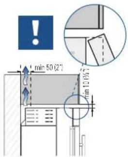
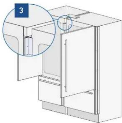
5.4 Maximum cabinet depth over "Integrated" refrigerator with single door panel
It is possible that the design of the kitchen and, in particular, of the niche where the "Integrated" refrigerator is going to be fitted includes a cabinet right above the refrigerator itself that must be closed with the same panel mounted on the Integrated refrigerator door."
In this case, the total depth of the cabinet without the door (above the refrigerator) must not exceed the total depth of the refrigerator itself [1].
This will allow the panel attached to the refrigerator door to open correctly without interference during its rotation up to 105°.
1
natural_image
Technical line drawing of a door frame with open lid and internal partition (no text or symbols)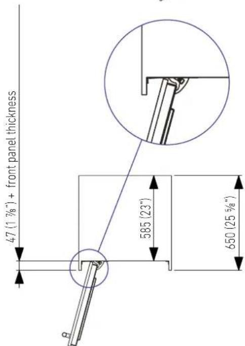
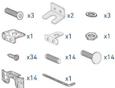
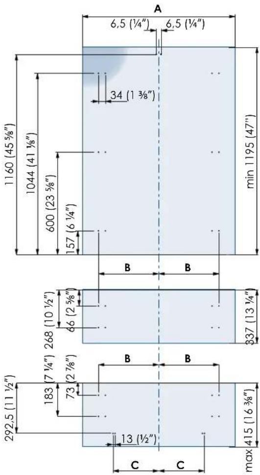
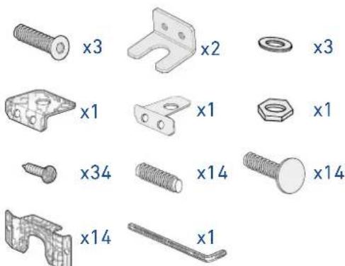
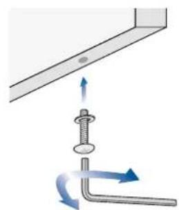
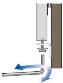
6.1 Anti-tipping safety assembly

To prevent the appliance from tipping over an extra-long kit is vailable up on request if the appliance needs to remain distanced from the wall, it is mandatory to install two brackets on the upper part of the appliance for fixing it securely to the wall.
Operate as follows:
The brackets should be applied as illustrated using the provided screws and expansion plugs. Place a bracket on the top of the appliance in correspondence to the fixing holes and against the wall [1].
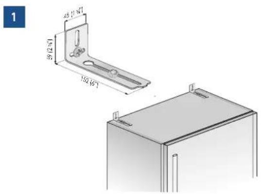
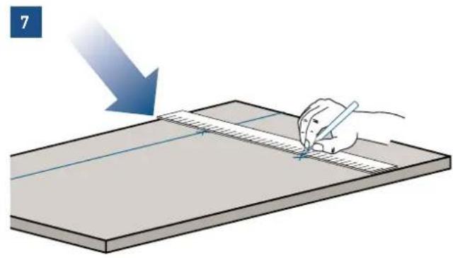
Mark up the holes position on the wall [2].
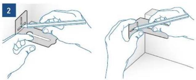
natural_image
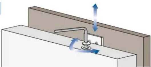
Illustration showing two hands using a ruler to cut a rectangular object, no text or symbols presentDrill the wall with an 8 mm (3/8") bit and insert the expansion plug [3].
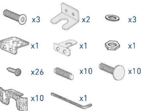
B04000200 Anti-tip kit
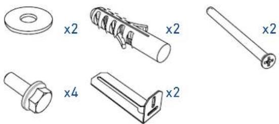
natural_image
Technical drawings of mechanical components including washers, springs, and bolts (no text or symbols)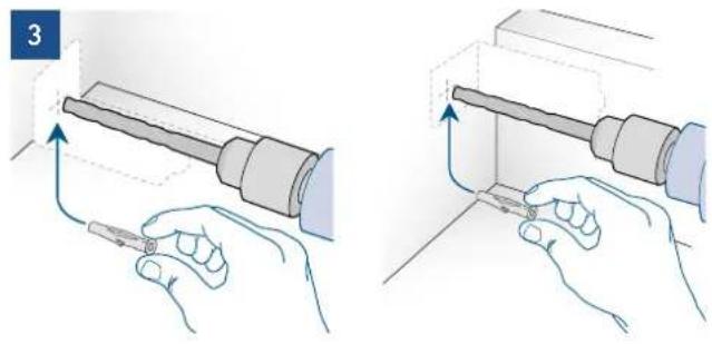
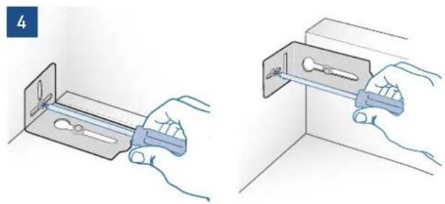
natural_image
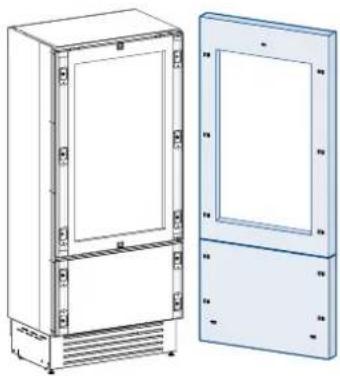
Illustration of two hands holding a tool, showing a mechanical assembly with arrows indicating motion (no text or symbols present)Reposition the bracket and fix it first to the cabinet and then to the wall [4].
natural_image
Illustration of two hands installing or adjusting a metal bracket component (no text or symbols present)
To avoid danger of the appliance tipping over it is mandatory to secure the appliance to the wall by means of two special brackets.
6.2 Mounting the handles on stainless front

To mount the handles onto the door and the drawer operate as follows:
Operate as follows:
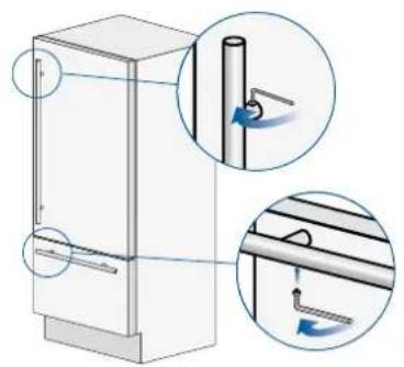
Insert the two handle spacers onto the supports already available on the door and the drawer [1].
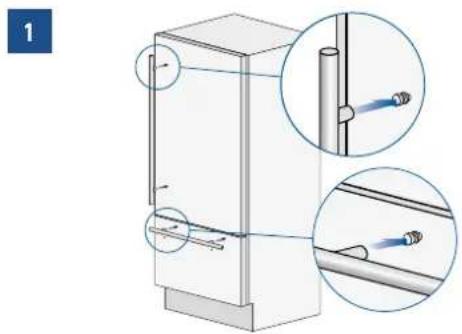
Screw in the Allen screws available on the handle [2].
2
natural_image
Diagram of a refrigerator with two views showing internal components and directional arrows (no text or symbols)The screws must be tightened in by means of a 2.5 mm (1/8") hex wrench.
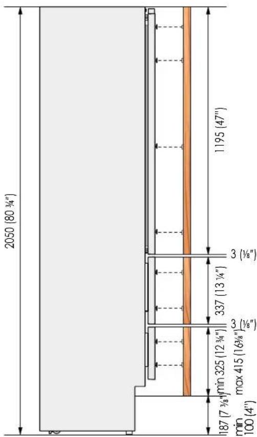
6.3 Ventilation and Plinth
INTEGRATED AND CLASSIC SERIES
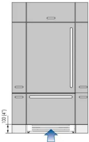
In the event that the design of the environment provides for the installation of a front plinth to unify the overall view, it is necessary to use a perforated plinth to ensure proper ventilation of the equipment.
The drawings below indicate, for each width available in the Integrated series, the size of the area and the percentage of surface to be drilled; the type of drilling (vertical or horizontal grid, for example) remains at the discretion of the designer.
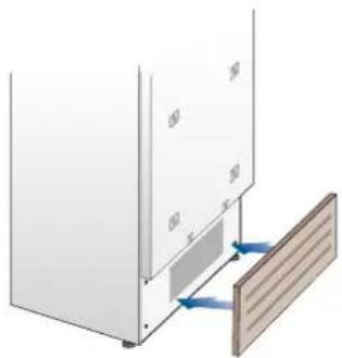
natural_image
Diagram of a wall-mounted panel with a wooden panel and blue directional arrows indicating movement or force (no text or symbols)Ventilation is ensured by a forced air system through a grid positioned in the lower part of the equipment. If a front plinth is provided, it must provide an opening to ensure proper ventilation of the equipment as per drawing.
The type of drilling of the front plinth (eg vertical or horizontal slots) is at the discretion, however, it must guarantee an open surface equal to 50% of the total.
In this case, to further improve ventilation, it is suggested to remove the original grille.
The ventilation grille is magnetically fixed to the equipment and can be easily removed, even by the user, to check and clean the condenser from any accumulation of dust.
The ventilation grille must not be blocked or covered in any way. It also needs to be dusted / cleaned regularly.
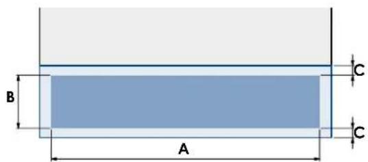
| SERIE 899 SERIE 749 SERIE 599 SERIE 449 | ||||
| A | 860 (33 7/8") | 710 (27 15/16") | 560 (22") | 410 (16 1/8") |
| B | >100 (4") | |||
| C | 10 (3/8") | |||
| min 50% | ||||
natural_image
Technical line drawing of a cabinet or enclosure with door, windows, and ventilation duct (no text or symbols)Plinth size
| Models | X-Pro (XS) County (AS) Classic | (KS) Integrated | (S) Brilliance | Classic (BS) | Brilliance Integrated (BC) | |
| Feet Adjustment | 0 - 25 mm (0 - 1" in) | |||||
| Height of the panel from the floor | 97 mm(3 7/8" in) | 128 mm(5 1/8" in) | 146 mm(5 3/4" in) | min 100 mm(3 7/8" in)max 187 mm(7 3/8" in) | 146 mm(5 3/4" in) | min 100 mm(3 7/8" in)max 187 mm(7 3/8" in) |
Series: X-Pro Series: Country Series: Classic
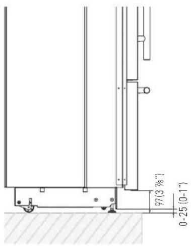
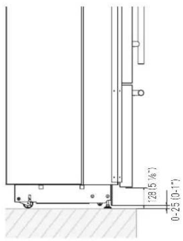

Series: Integrated

Series: Brilliance Classic Series: Brilliance Integrated
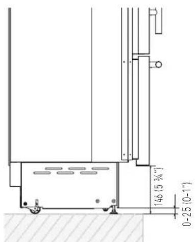


Based on the adjustment of the feet and the height of the panel from the floor, the customer defines the perforated plinth to be installed on the equipment.
X-PRO SERIES:
Ventilation is insured by a forced air system through a grille located in the upper part of the appliance. This grille should never be covered by panels or any other devices that could reduce its efficiency. Please refer to page 5-6 to ensure correct air circulation.
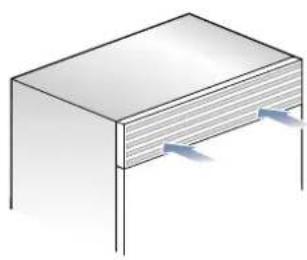
natural_image
Isometric illustration of a rectangular electronic component with two side supports and a central slot (no text or symbols)6.4 Post installation control
√ Check that the front levelling feet have been properly installed.
√ Check that the connection to the water system does not have any leaks and that the closing tap is easily accessible.
√ Check that the electrical connection is correctly installed and that the multipole switch and socket are easily accessible.
√ Check the perfect alignment of the appliance with adjacent structures.
√ Check that all adhesive tape and external or internal temporary protective devices have been removed.
√ Check the perfect closing of the doors and the smooth sliding of the drawers and shelves.
6.5 Start up
To start the appliance, connect the plug to the electrical mains: at this point, when opening the door, the control panel will usually visualize the message "Stand by", and all the panel keys be off
Stand be
To turn on all the appliance compartments, press the Unit ⏻ button for three seconds. The display will show the message "Initial test" for approx. 2 minutes. After this phase the compressors will start up and remain on until the default temperature set up in the factory is reached. Do bear in mind that this condition could last several hours. If the appliance is provided with an Ice Maker, prior to switching it on make sure that the water filter cartridge is installed, then fill the water system. To this purpose switch off the Ice Maker and perform a manual clean procedure. At the end switch the Ice Maker on again by touching the ⏻ button.

For further information about the appliance operation, refer to the User Manual.

If at the first start - up the message Stand by does not appear, but other messages appear, such as Fridge too warm, Fresco too warm, Freezer too warm, or sound signals are activated, it means that the appliance has already started the cooling process. If this is the case, deactivate any possible acoustic signals by pressing the Alarm button, close the door and wait until the set temperature is reached.

It is necessary to let the unit reach the correct temperature before foods are stored inside.
- TECHNICAL REQUIREMENTS 42
- PREPARING TO INSTALL 54
- PANELS MOUNTING 56
- INSTALLATION 70
- COMPLETING THE INSTALLATION 74
- IMPORTANT INSTRUCTIONS
- TECHNICAL REQUIREMENTS
- Important safely instruction
- Note
- Important
- Warning
- Children safety
- Important!
- Appliance features and installation requirements
- Installation niche features: Integrated Series, 1T - 0T - 0H Models
- Minimum Niche Depth
- Door Swing Clearance
- Door Opening Angle
- Width \*
- Depth with door (without panel)
- Installation niche features: Integrated Series, OF Column Models
- Minimum Niche Height
- Installation niche features: Classic Series, 1T - 0T - 0H Models
- Minimum Niche Width
- Height
- Depth with door
- Minimum distance from the wall (hinge side) with door at 105° and 90°.
- Installation niche features: Classic Series, OF Column Models
- Installation niche features: X-Pro Series
- Width
- Installation niche features: X-Pro Series: - OF Column Models
- Installation niche features: Country Series
- Installation niche features: Brilliance-Integrated Series
- Installation niche features: Brilliance-Classic Series
- Transport to installation site and unpacking
- Operate as follows:
- Electrical and Water connection
- ELECTRICAL AND WATER SUPPLY BEHIND THE UNIT
- INTEGRATED AND CLASSIC SERIES:
- Levelling
- INTEGRATED SERIES
- Decorative door and bottom-drawer panels layout
- Door Panel
- Drawer Panel
- Decorative panels layout for Fridge with one Bottom-Drawer (1T/0T)
- Decorative panels layout for Fridge with two Bottom-Drawers (0H)
- Decorative panels layout
- for Fridge with glass door and one Bottom-Drawer (1T/0T)
- Decorative panels layout for Fridge with glass door Brilliance
- Decorative panels layout for Fridge with glass door and two Bottom-Drawers (OH)
- Decorative panels layout for Fridge Column (OF)
- Decorative panels layout for Fridge column with glass door (OF)
- Panels Dimensions One Bottom - Drawer (1T/0T models)
- Panels DimensionsTwo Bottom - Drawers (OH models)
- Panels Dimensions Column Models (OF models)
- Mounting the handles
- Mounting panels to the door and the drawer
- Built-in installation single appliance
- 1
- 2
- 3
- Built-in installation two or more appliances
- Required accessories to be ordered separately:
- Free-standing installation two or more appliances
- Maximum cabinet depth over "Integrated" refrigerator with single door panel
- Anti-tipping safety assembly
- Mounting the handles on stainless front
- Ventilation and Plinth
- INTEGRATED AND CLASSIC SERIES
- X-PRO SERIES:
- Post installation control
- Start up
Brand : Fhiaba
Model : XS7490TWT3A
Category : Wine cellar