
ChainDrive - Audio module Radial Engineering - Free user manual and instructions
Find the device manual for free ChainDrive Radial Engineering in PDF.

| Product Type | 500 Series 1x4 Distribution Amplifier Module |
| Brand | Radial Engineering |
| Model | ChainDrive |
| Category | Audio Signal Distribution |
| Frequency Response | 20 Hz – 20 kHz |
| Maximum Input Level | +24 dBu |
| Maximum Output Level | +28 dBu |
| THD + N | < 0.001% |
| Dynamic Range | 124 dB |
| Input Impedance | 10 kΩ |
| Output Impedance | 600 Ω (balanced) / 300 Ω (unbalanced) |
| Power Requirement | ±16 V DC, 33 mA total current draw |
| Number of Output Channels | 4 |
| Output Connections | 4 x 1/4" TRS (balanced or unbalanced) |
| Input Connection | XLR (via 500 rack backplane) or Omniport (1/4" TS) |
| Controls | Individual level knobs for each output channel |
| Omniport | Converts unbalanced high-impedance input to balanced low-impedance output |
| Front Panel Indicator | Power LED |
| Warranty | 3 years, transferable |
| Dimensions (approx.) | 5.25" x 1.5" x 7" (133 x 38 x 178 mm) |
| Weight (approx.) | 1.1 lb (0.5 kg) |
| Color | Black |
Frequently Asked Questions - ChainDrive Radial Engineering
User questions about ChainDrive Radial Engineering
0 question about this device. Answer the ones you know or ask your own.
Ask a new question about this device
Download the instructions for your Audio module in PDF format for free! Find your manual ChainDrive - Radial Engineering and take your electronic device back in hand. On this page are published all the documents necessary for the use of your device. ChainDrive by Radial Engineering.
USER MANUAL ChainDrive Radial Engineering
Table of Contents Page
Overview....1
Features 2
Making Connections....3
Using the ChainDrive....4
Ominport....6
Specifications 7
Block Diagram....7
Radial Limited Warranty ....Back Cover
Congratulations on your purchase of the Radial ChainDrive, an innovative 500 series module that lets you distribute four balanced line-level signals to effect processors, preamps and just about any other audio input from your 500 series rack.
Although the ChainDrive is designed to be intuitive and easy to use, we recommend that you take a minute to read this short manual to make sure you take full advantage of the many features that are built in. Should you find yourself asking a question that is not addressed, we invite you to view the ChainDrive FAQ page on our website. This is where we post the latest hints and of course questions from users. If you still do not find what you are looking for, feel free to send an email to info@radialeng.com and we will do our very best to respond to you in short order.
Now get ready to patch, process and listen to the ChainDrive because this is what audio engineers love to do the most!

WARNING NOTICE TO USER!
Although preventative safety measures have been designed into Radial 500 series products we strictly advise against hot swapping modules or plugging and unplugging them when the Workhorse or other 500 series rack is powered on. Hot swapping can cause connection sparks at the card-edge connector that could send damaging transients to other equipment. This also greatly reduces the life span of the contacts. Damage due to hot swapping is not covered under warranty. There are no user serviceable parts inside.
OVERVIEW
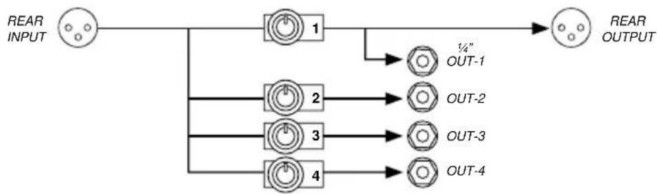
The ChainDrive is an innovative 1x4 'distro' module designed to fit inside the popular 500 series rack format. It follows convention with a 15-pin card-edge connector so that it works in all 500 series power racks. Once connected, it enables the engineer to send four balanced or unbalanced audio signals to various processors, effects or remote audio systems simultaneously as a means to create innovative signal paths.
flowchart
graph LR
    A["Input"] --> B["1"]
    B --> C["OUT-1 1/4""]
    B --> D["OUT-2"]
    B --> E["OUT-3"]
    B --> F["OUT-4"]
    D --> G["Output"]
    E --> H["Output"]
    F --> I["Output"]
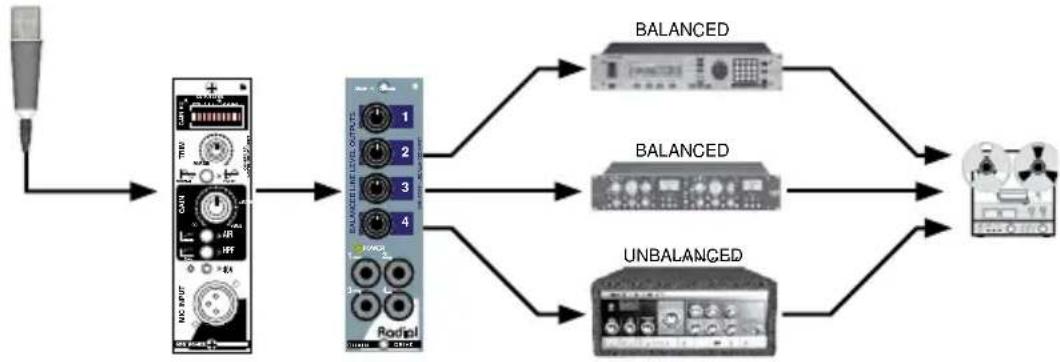
Applications include splitting the signal for parallel processing like multi-band compression or feeding a variety of effects processors simultaneously.
flowchart
graph LR
    A["Input"] --> B["Audio Input"]
    B --> C["Redo/Dial DAC"]
    C --> D["BALANCED"]
    C --> E["BALANCED"]
    C --> F["UNBALANCED"]
    D --> G["Output Device"]
    E --> G
    F --> G
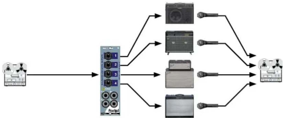
The ChainDrive can distribute a line signal for Reamping where a clean instrument track from a multitrack recorder is fed to various guitar amps and the sound re-recorded to new tracks.
flowchart
graph LR
    A["Input Device"] --> B["Balanced Level Output"]
    B --> C1["1"]
    B --> C2["2"]
    B --> C3["3"]
    B --> C4["4"]
    B --> D1["Podipl"]
    C1 --> E1["Image 1"]
    C2 --> E2["Image 2"]
    C3 --> E3["Image 3"]
    C4 --> E4["Image 4"]
    D1 --> F1["Podipl"]
    D2 --> F2["Podipl"]
    D3 --> F3["Podipl"]
    D4 --> F4["Podipl"]
    F1 --> G1["Output Device 1"]
    F2 --> G2["Output Device 2"]
    F3 --> G3["Output Device 3"]
    F4 --> G4["Output Device 4"]
REORDER OUT CHAINDRIVE RECORDER INAMPLIFIERS MICS & PREAMPS
FEATURE SET
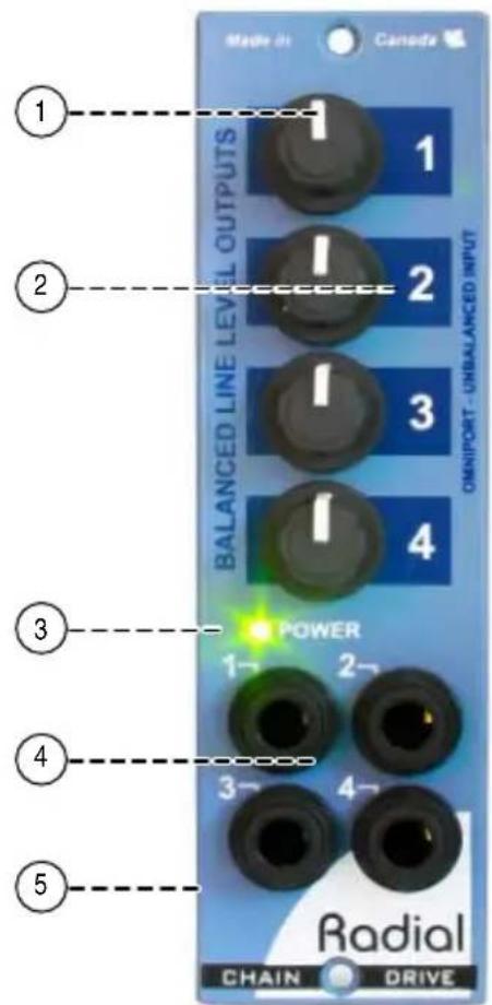
- LEVEL CONTROLS 1 THRU 4: Used to set the output gain for each channel on the ChainDrive.
- LARGE ID NUMBERS: Make it easy to read and quick to adjust. This is particularly important given the compact nature of 500 series modules.
- POWER ON LED: Convenient front panel LED indicator lets you know the ChainDrive is properly connected and power is present.
- OUTPUTS 1 THRU 4: Balanced line 14 " TRS outputs for each of the four channels. May also be used as an unbalanced output or a TRS stereo out depending on the source you have connected.
- OMNIPORT: Unbalanced input with auto-balancing circuitry and priority switching. Used to convert an unbalanced signal to balanced.
GETTING STARTED
Although the ChainDrive is extremely easy to use, we suggest you follow these simple instructions before getting started. As with all audio equipment, always ensure all levels are turned down and equipment is turned off before making any connections or inserting the ChainDrive into a 500 series power rack. This common practice ensures turn-on transients will not damage more sensitive components such as tweeters. Secure the module in the 500 rack using the supplied machine screws to ensure it does not accidentally become dislodged. To prevent damage to the rack frame do not over-tighten the mounting screws.
Most 500 series racks are equipped with balanced XLR connectors. This is augmented with 1/4 ” TRS and D-sub connectors if using the ChainDrive in a Radial Workhorse series rack. When you insert the ChainDrive into your 500 series rack, it will automatically route the rear panel XLR connections to the module's input and output. The ChainDrive follows the AES standard with pin-2 hot (+), pin-3 cold (-). Most devices are wired this way but older vintage equipment should be checked to confirm compatibility with AES standards.
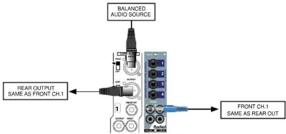
Connecting balanced sources
Connect a balanced line-level audio signal to the ChainDrive input using a standard XLR patch cable. The signal is distributed to the balanced TRS 1/4" outputs. The ChainDrive's output on the rear panel of your 500 rack is identical to output-1 on the front. The level for both outputs is set using the level-1 volume control. All outputs are variable from infinity to a maximum of +24dBu.
flowchart
graph TD
    A["BALANCED AUDIO SOURCE"] --> B["CARD Slot"]
    B --> C["READ"]
    C --> D["CLK"]
    D --> E["OUTPUT"]
    E --> F["OR/IMPORT"]
    F --> G["1"]
    G --> H["OUTPUT INPUT"]
    I["FRONT CH.1 SAME AS REAR OUT"] --> J["Radial"]
    K["REAR OUTPUT SAME AS FRONT CH.1"] --> L["Switch Output"]
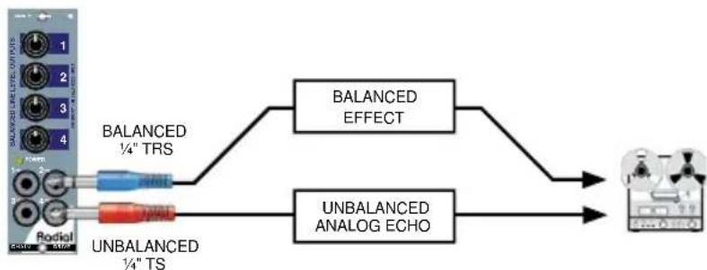
Connect the ChainDrive's front panel outputs to your audio devices using 14 " TRS type cables for balanced gear or standard instrument 14 " TS cables for unbalanced, hi-impedance audio devices. You may need to use an adapter to connect to the input of your audio devices depending on what type of input jacks it uses. Because each output is individually buffered, it is possible to connect to balanced and unbalanced audio devices at the same time.
flowchart
graph LR
    A["Microcontroller 1-4"] --> B["BALANCED ¼" TRS"]
    A --> C["UNBALANCED ¼" TS"]
    B --> D["BALANCED EFFECT"]
    C --> E["UNBALANCED ANALOG ECHO"]
    D --> F["Output"]
    E --> F
Connecting unbalanced sources
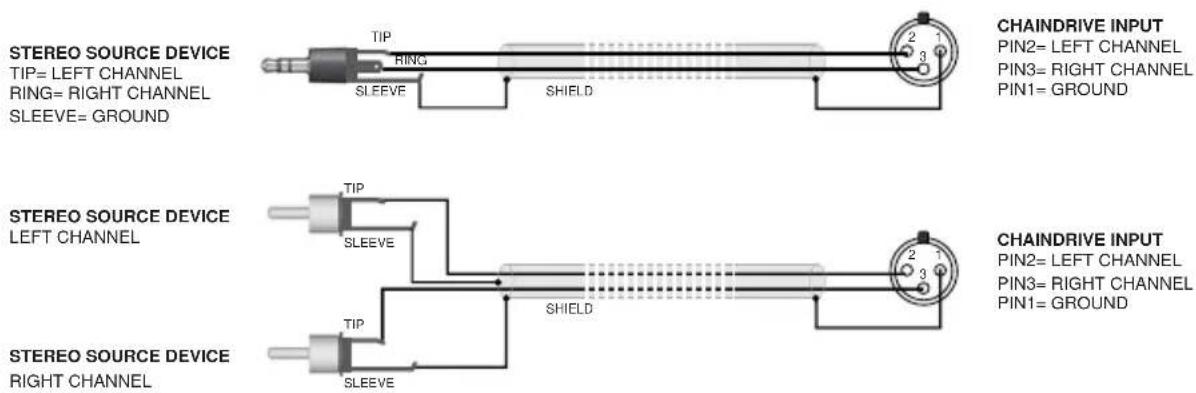
The ChainDrive can distribute unbalanced line-level signals from electronic instruments like keyboards and samplers. To interface an unbalanced audio device to the ChainDrive's input an adapter cable is needed that terminates in a 3-pin male XLR connector where pin-1 is ground, pin-2 is hot, and pin-3 is left open.

Once connected, the ChainDrive distributes unbalanced signals via the four front panel 14 " outputs. Connect the outputs using standard 14 " instrument cables. The output level is variable from infinity to +18dBu with an unbalanced input.
Connecting stereo sources
The ChainDrive can also be used to distribute an unbalanced stereo signal to the four stereo outputs. To interface an unbalanced stereo device to the ChainDrive's input an adapter cable is needed that terminates in a 3-pin male XLR connector where pin-1 is ground, pin-2 is the left channel, and pin-3 is right channel.
Connecting stereo outputs
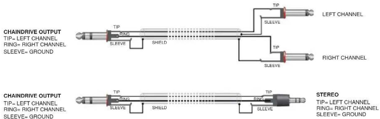
A stereo adapter cable is used to interface the ChainDrive's front panel 14 " TRS outputs to the inputs of your unbalanced stereo devices. Here, the ChainDrive's 14 " TRS outputs are configured like stereo headphones where the tip is the left channel, the ring is the right channel, and the sleeve is a common ground.
USING THE CHAINDRIVE
How you choose to use the ChainDrive will depend on the task at hand. The ChainDrive can distribute high quality audio signals where needed and be a handy problem solver. As a creative tool, the ChainDrive makes experimenting easy and fun. The following are just a few useful configurations that you can try.
Parallel processing
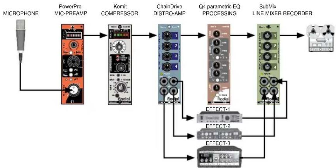
Parallel processing involves splitting the signal and applying multiple processors at the same time. The output of the processors is recorded to individual tracks or mixed together to one track. Bellow is a processing chain where a vocal track is parallel-processed through the Radial Q4 parametric equalizer and three effects devices. The signals are mixed using the Radial Submix 500 series line mixer.
flowchart
graph LR
    A["MICROPHONE"] --> B["PowerPre MIC-PREAMP"]
    B --> C["Komit COMPRESSOR"]
    C --> D["ChainDrive DISTRO-AMP"]
    D --> E["Q4 parametric EQ PROCESSING"]
    E --> F["SubMix LINE MIXER RECORDER"]
    F --> G["Output"]

    B --> H["Radio1"]
    C --> I["Radio2"]
    D --> J["Radio3"]
    E --> K["Radio4"]
    F --> L["Radio5"]

    style A fill:#f9f,stroke:#333
    style G fill:#ccf,stroke:#333

    subgraph Effect1
        M["EFFECT-1"]
        N["EFFECT-2"]
        O["EFFECT-3"]
    end

    subgraph Effect2
        P["EFFECT-2"]
        Q["EFFECT-3"]
    end

    subgraph Effect3
        R["EFFECT-3"]
    end
Multiband processing
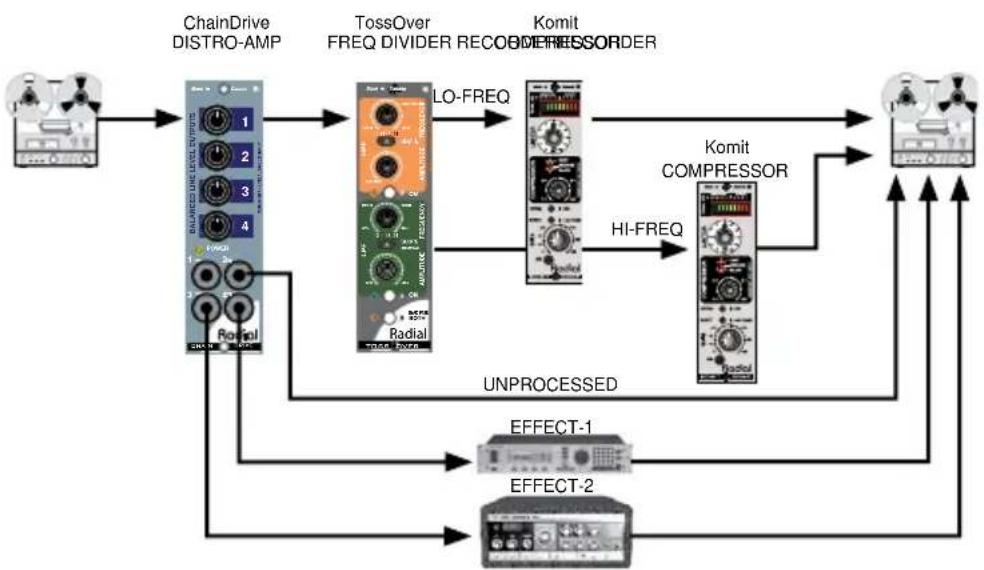
Similar to parallel processing, multiband processing uses a frequency divider (electronic cross-over) to divide the original signal into high and low bands for separate processing and finer control. Here, the ChainDrive distributes the signal to the Radial Tossover 500 series crossover for multiband compression using two Radial Komit 500 series compressors. An unprocessed safety track and two effect tracks are also recorded.
flowchart
graph TD
    A["Host"] --> B["ChainDrive DISTRO-AMP"]
    B --> C["TossOver FREQ DIVIDER RECOODER"]
    C --> D["Komit COMPRESSOR"]
    D --> E["Output"]
    C --> F["Komit COMPRESSOR"]
    F --> G["HI-FREQ"]
    G --> D
    C --> H["UNPROCESSED"]
    H --> I["EFFECT-1"]
    H --> J["EFFECT-2"]
    I --> K["Output"]
    J --> K
Re-amping with guitar pedals and amps
Reamping instrument parts with the ChainDrive has a lot of advantages. The front panel jacks and level controls make it especially easy to connect high impedance guitar pedals and amps. Simply feed a pre-recorded clean track from your DAW to the ChainDrive input. The four level controls will allow you to set the level. Connect a ChainDrive output to a guitar amp and use a mic to record the Reamp'ed sound. Or ditch the amp completely and record the output of a digital guitar processor. The ChainDrive will interface with all kinds of high impedance audio devices.

flowchart
graph LR
    A["Reorder Out ChainDrive Recorder IN"] --> B["Level/mps"]
    B --> C["Amplifiers MICS & PREAMS"]
    B --> D["Amplifiers MICS & PREAMS"]
    B --> E["Amplifiers MICS & PREAMS"]
    B --> F["Amplifiers MICS & PREAMS"]
    B --> G["Amplifiers MICS & PREAMS"]
    B --> H["Amplifiers MICS & PREAMS"]
    B --> I["Amplifiers MICS & PREAMS"]
    B --> J["Amplifiers MICS & PREAMS"]
    B --> K["Amplifiers MICS & PREAMS"]
    B --> L["Amplifiers MICS & PREAMS"]
    B --> M["Amplifiers MICS & PREAMS"]
    B --> N["Amplifiers MICS & PREAMS"]
    B --> O["Amplifiers MICS & PREAMS"]
    B --> P["Amplifiers MICS & PREAMS"]
    B --> Q["Amplifiers MICS & PREAMS"]
    B --> R["Amplifiers MICS & PREAMS"]
    B --> S["Amplifiers MICS & PREAMS"]
    B --> T["Amplifiers MICS & PREAMS"]
    B --> U["Amplifiers MICS & PREAMS"]
    B --> V["Amplifiers MICS & PREAMS"]
    B --> W["Amplifiers MICS & PREAMS"]
    B --> X["Amplifiers MICS & PREAMS"]
    B --> Y["Amplifiers MICS & PREAMS"]
    B --> Z["Amplifiers MICS & PREAMS"]
    B --> AA["Amplifiers MICS & PREAMS"]
    B --> AB["Amplifiers MICS & PREAMS"]
    B --> AC["Amplifiers MICS & PREAMS"]
    B --> AD["Amplifiers MICS & PREAMS"]
    B --> AE["Amplifiers MICS & PREAMS"]
    B --> AF["Amplifiers MICS & PREAMS"]
    B --> AG["Amplifiers MICS & PREAMS"]
    B --> AH["Amplifiers MICS & PREAMS"]
    B --> AI["Amplifiers MICS & PREAMS"]
    B --> AJ["Amplifiers MICS & PREAMS"]
    B --> AK["Amplifiers MICS & PREAMS"]
    B --> AL["Amplifiers MICS & PREAMS"]
    B --> AM["Amplifiers MICS & PREAMS"]
    B --> AN["Amplifiers MICS & PREAMS"]
    B --> AO["Amplifiers MICS & PREAMS"]
    B --> AP["Amplifiers MICS & PREAMS"]
    B --> AQ["Amplifiers MICS & PREAMS"]
    B --> AR["Amplifiers MICS & PREAMS"]
    B --> AS["Amplifiers MICS & PREAMS"]
    B --> AT["Amplifiers MICS & PREAMS"]
    B --> AU["Amplifiers MICS & PREAMS"]
    B --> AV["Amplifiers MICS & PREAMS"]
    B --> AW["Amplifiers MICS & PREAMS"]
    B --> AX["Amplifiers MICS & PREAMS"]
    B --> AY["Amplifiers MICS & PREAMS"]
    B --> AZ["Amplifiers MICS & PREAMS"]
    B --> BA["Amplifiers MICS & PREAMS"]
    B --> BB["Amplifiers MICS & PREAMS"]
    B --> BC["Amplifiers MICS & PREAMS"]
    B --> BD["Amplifiers MICS & PREAMS"]
    B --> BE["Amplifiers MICS & PREAMS"]
    B --> BF["Amplifiers MICS & PREAMS"]
    B --> BG["Amplifiers MICS & PREAMS"]
    B --> BH["Amplifiers MICS & PREAMS"]
    B --> BI["Amplifiers MICS & PREAMS"]
    B --> BJ["Amplifiers MICS & PREAMS"]
    B --> BK["Amplifiers MICS & PREAMS"]
    B --> BL["Amplifiers MICS & PREAMS"]
    B --> BM["Amplifiers MICS & PREAMS"]
    B --> BN["Amplifiers MICS & PREAMS"]
    B --> BO["Amplifiers MICS & PREAMS"]
    B --> BP["Amplifiers MICS & PREAMS"]
    B --> BQ["Amplifiers MICS & PREAMS"]
    B --> BR["Amplifiers MICS & PREAMS"]
    B --> BS["Amplifiers MICS & PREAMS"]
    B --> BT["Amplifiers MICS & PREAMS"]
    B --> BU["Amplifiers MICS & PREAMS"]
    B --> BV["Amplifiers MICS & PREAMS"]
    B --> BW["Amplifiers MICS & PREAMS"]
Omniport hi-z to low-z converter
If you are using the ChainDrive in a Radial Workhorse power rack, the Omniport is designated as an unbalanced, hi-z input for line-level signals. The input is converted to a low-z balanced signal allowing the ChainDrive to distribute signal to balanced devices. When a plug is inserted into the Omniport, the module's main XLR input is disabled.

flowchart
graph LR
    A["UNBAL LINE INSTRUMENT"] --> B["ChainDrive OMNIPORT"]
    B --> C["Q4 parametric EQ PROCESSING"]
    C --> D["SubMix LINE MIXER RECORDER"]
    D --> E["Output"]
    B --> F["Radio/Signal"]
    C --> G["Radio/Signal"]
    F --> H["Radio/Signal"]
    G --> I["Radio/Signal"]
    H --> J["Radio/Signal"]
    I --> K["Radio/Signal"]
    J --> L["Radio/Signal"]
    K --> M["Radio/Signal"]
    L --> N["Radio/Signal"]
    M --> O["Radio/Signal"]
    N --> P["Radio/Signal"]
    O --> Q["Radio/Signal"]
    P --> R["Radio/Signal"]
    Q --> S["Radio/Signal"]
    R --> T["Radio/Signal"]
    S --> U["Radio/Signal"]
    T --> V["Radio/Signal"]
    U --> W["Radio/Signal"]
    V --> X["Radio/Signal"]
    W --> Y["Radio/Signal"]
    X --> Z["Radio/Signal"]
    Y --> AA["Radio/Signal"]
    Z --> AB["Radio/Signal"]
RADIAL CHAINDRIVE 500 SPECIFICATIONS
Circuit Type..... Low noise active distribution amplifier
Frequency Response 20Hz to 20kHz
Maximum Input ....+24dBu
Maximum Output ....+28dBu
THD + N .... <0.001%
Dynamic Range 124dB
Equivalent Input Noise....-104dBu
Noise -100dBu
Intermodulation Distortion....<0.002%
CMR Ratio 53dB
Input Impedance 10K Ohms
Output Impedance 600/300 Ohms balanced/unbalanced
Omniport Function ...... Converts unbalanced input to balanced output
Power Requirement +/- 16V 33mA total current draw
Warranty 3 years transferable
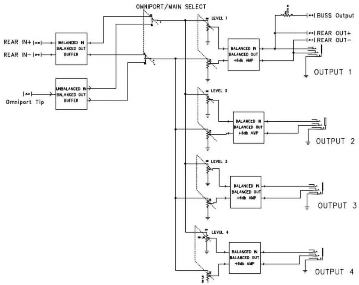
RADIAL CHAINDRIVE 500 BLOCK DIAGRAM
flowchart
graph TD
    A["REAR IN+"] --> B["BALANCED IN BALANCED OUT BUFFER"]
    C["REAR IN-"] --> B
    D["Omniport Tip"] --> E["UNBALANCED IN BALANCED OUT BUFFER"]
    B --> F["OMNIPORT/MAIN SELECT"]
    E --> F
    F --> G["LEVEL 1"]
    F --> H["LEVEL 2"]
    F --> I["LEVEL 3"]
    F --> J["LEVEL 4"]
    G --> K["BALANCED IN BALANCED OUT +6db ANP"]
    H --> L["BALANCED IN BALANCED OUT +6db ANP"]
    I --> M["BALANCED IN BALANCED OUT +6db ANP"]
    J --> N["BALANCED IN BALANCED OUT +6db ANP"]
    K --> O["OUTPUT 1"]
    L --> P["OUTPUT 2"]
    M --> Q["OUTPUT 3"]
    N --> R["OUTPUT 4"]
    O --> S["BUSS Output"]
    P --> T["REAR OUT+"]
    P --> U["REAR OUT-"]
THREE YEAR TRANSFERABLE LIMITED WARRANTY
RADIAL ENGINEERING LTD. ("Radial") warrants this product to be free from defects in material and workmanship and will remedy any such defects free of charge according to the terms of this warranty. Radial will repair or replace (at its option) any defective component(s) of this product (excluding finish and wear and tear on components under normal use) for a period of three (3) years from the original date of purchase. In the event that a particular product is no longer available, Radial reserves the right to replace the product with a similar product of equal or greater value. In the unlikely event that a defect is uncovered, please call 604-942-1001 or email service@radialeng.com to obtain an RA number (Return Authorization number) before the 3 year warranty period expires. The product must be returned prepaid in the original shipping container (or equivalent) to Radial or to an authorized Radial repair center and you must assume the risk of loss or damage. A copy of the original invoice showing date of purchase and the dealer name must accompany any request for work to be performed under this limited and transferable warranty. This warranty shall not apply if the product has been damaged due to abuse, misuse, misapplication, accident or as a result of service or modification by any other than an authorized Radial repair center.
THERE ARE NO EXPRESSED WARRANTIES OTHER THAN THOSE ON THE FACE HEREOF AND DESCRIBED ABOVE. NO WARRANTIES WHETHER EXPRESSED OR IMPLIED, INCLUDING BUT NOT LIMITED TO, ANY IMPLIED WARRANTIES OF MERCHANTABILITY OR FITNESS FOR A PARTICULAR PURPOSE SHALL EXTEND BEYOND THE RESPECTIVE WARRANTY PERIOD DESCRIBED ABOVE OF THREE YEARS. RADIAL SHALL NOT BE RESPONSIBLE OR LIABLE FOR ANY SPECIAL, INCIDENTAL OR CONSEQUENTIAL DAMAGES OR LOSS ARISING FROM THE USE OF THIS PRODUCT. THIS WARRANTY GIVES YOU SPECIFIC LEGAL RIGHTS, AND YOU MAY ALSO HAVE OTHER RIGHTS, WHICH MAY VARY DEPENDING ON WHERE YOU LIVE AND WHERE THE PRODUCT WAS PURCHASED.

This product is intended for professional use only. The user should be familiar and experienced with the 500 series rack and module format.

Radial Engineering Ltd.
1588 Kebet Way, Port Coquitlam, BC, V3C 5M5
tel: 604-942-1001 • fax: 604-942-1010
info@radialeng.com • www.radialeng.com


- Table of Contents Page
- WARNING NOTICE TO USER!
- OVERVIEW
- FEATURE SET
- GETTING STARTED
- Connecting balanced sources
- Connecting unbalanced sources
- Connecting stereo sources
- Connecting stereo outputs
- USING THE CHAINDRIVE
- Parallel processing
- Multiband processing
- Re-amping with guitar pedals and amps
- Omniport hi-z to low-z converter
- RADIAL CHAINDRIVE 500 SPECIFICATIONS
- THREE YEAR TRANSFERABLE LIMITED WARRANTY
Brand : Radial Engineering
Model : ChainDrive
Category : Audio module