
CC30W - Bar Perlick - Free user manual and instructions
Find the device manual for free CC30W Perlick in PDF.

| Product Type | Column Refrigerator (Bar) |
| Brand | Perlick |
| Model | CC30W |
| Width | 30 inches (762 mm) |
| Depth | 24 inches (610 mm) |
| Height (Typical) | 84 inches (2134 mm) with 1/8" reveals |
| Weight (Empty, Estimated) | 200 lbs (91 kg) |
| Floor Load Capacity (Fully Stocked) | 650 lbs (295 kg) |
| Electrical Supply | 115V, 60Hz, 3.2 Amps, single phase |
| Circuit Requirement | Dedicated 15 amp circuit |
| Power Cord | NEMA 5-15, 5 ft (1.5 m) length |
| Refrigerant | R600a (eco-friendly, no HFCs) |
| Temperature Range | 40°F to 68°F (4°C to 20°C) |
| Factory Presets | White Wine 50°F, Red Wine 60°F, Cellar 55°F |
| Digital Control | PerlIQ™ touch screen with temperature zones, lighting, Sabbath mode |
| Lighting | LED, adjustable white to blue, theater lighting |
| Door Opening | 105° standard, 90° stop available |
| Hinge | Soft close activation (T20 Torx screw) |
| Installation | Built-in or freestanding, front-breathing |
| Anti-Tip Bracket | Required, included with unit |
| Air Filter | Carbon filter, replace every 6 months |
| Door Overlay Panel | Custom panel up to 65 lbs (29 kg), total door weight max 120 lbs (54 kg) |
| Glass Door | Triple pane, UV protection |
| Cleaning | Stainless steel (non-abrasive, with grain), glass (alcohol-based cleaner) |
| Certifications | CARB compliant, no prohibited refrigerants |
Frequently Asked Questions - CC30W Perlick
User questions about CC30W Perlick
0 question about this device. Answer the ones you know or ask your own.
Ask a new question about this device
Download the instructions for your Bar in PDF format for free! Find your manual CC30W - Perlick and take your electronic device back in hand. On this page are published all the documents necessary for the use of your device. CC30W by Perlick.
USER MANUAL CC30W Perlick
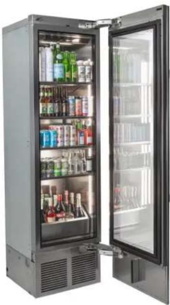
natural_image
Interior view of a stainless steel refrigerator with open shelves filled with various beverage cans and bottles (no visible text or labels)
Installation & Operation Manual
Column Refrigeration
For all second generation column refrigeration produced after 7/21/24
CC24B-2 CC30B-2
CR24B-2 CR30B-2
CC24C-2 CC30C-2
CR24C-2 CR30C-2
CC24D-2 CC30D-2
CR24D-2 CR30D-2
CC24W-2 CC30W-2
CR24W-2 CR30W-2

eco-friendly R600a Refrigerant
The Perlick Corporation verifies this product does not contain a prohibited refrigerant as defined by the California Air Resource Board (CARB), the state of New York, and any other state with HFC prohibition laws. This product does not contain HFC's. The following disclosure statement is provided to comply with the CARB regulation:
This equipment is prohibited from use in California with any refrigerants on the "List Of Prohibited Substances" for that specific end use, in accordance with the California Code of Regulations, title 17, section 95374. This disclosure statement has been reviewed and approved by the Perlick Corporation and the Perlick Corporation attests under penalty of perjury, that these statements are true and accurate.
TABLE OF CONTENTS
General Information......2
Safety Precautions/Site Preparation....3
Prior to Installation....4
Installation 5
Anti-Tip Bracket/Application 11
Placement and Alignment of Appliance 12
Installing Door Overlay Panel....15
24" Column Glass Door Template for 4"/6" Toe Kick 17
30" Column Glass Door Template for 4"/6" Toe Kick 19
24" Wine Shelf Front Detail 21
30" Wine Shelf Front Detail 22
Door Overlay Panel Adjustment 21
Door Trim Installation....22
Wine Storage and Shelving....26
Toe Kick Installation....28
Toe Kick Clearance....28
Air Filter Installation 29
Hinge Operation 29
PerliQ Digital Control Operation 30
Stainless Steel/Surface Care 33
Air Filtration Care....33
Troubleshooting....34
Column Install Checklist 36
GENERAL INFORMATION
Introduction
Congratulations on your purchase of a Perlick column refrigerator. This manual has been prepared to assist you in the installation of your cabinet and to acquaint you with its operation and maintenance.
We dedicate considerable time to ensure that our products provide the highest level of customer satisfaction. If service is required, your dealer can provide you with a list of qualified service agents. For your own protection, never return merchandise for credit without our approval.
We thank you for selecting a Perlick product and assure you of our continuing interest in your satisfaction.
Product Information
Additional product information, such as installation instructions, Use and Care Guides, Spec Sheets, CAD Drawings, Compliance Documentation and product warranty information can be referenced or downloaded at perlick.com.
Warranty Registration
To register your product, visit our web site at perlick.com. Or scan QR code located next to the product identification plate located behind the toe kick to complete a "Warranty Registration Form". You must complete and submit this form or the installation date will revert back to the ship date.
Please record the purchase date and the dealer's name, address and telephone number below.
Model Number: ____
Serial Number: ____
Purchase Date: ____
Dealer Name & Address
Phone Number ____
Product Identification Plate
Your product information can be found on the product's identification plate. The identification plate is located on the sidewall behind the toe kick plate. To access the identification plate, simply remove the toe kick plate (grill). The identification plate will be adhered to the right sidewall.
SAFETY
PLEASE READ all instructions completely before attempting to install or operate the unit. Take particular note of the DANGER, WARNING an CAUTION information in the manual. The information is important for the safe and efficient installation, operation and care of your Perlick unit.

Indicates a hazard that WILL result in
serious injury or death if precautions are not followed.

Indicates a hazard MAY cause serious injury or s are not followed.

Indicates a hazard w here minor injury or ay occur if precautions

Indicates that property damage may occur if actions are not followed.
IMPORTANT!
Read and understand all information in this manual before attempting the installation. All electrical work must be performed by a qualified technician and conform to all applicable state and local codes.
! WARNING: California Prop 65 Notice
These products may expose you to chemicals including Chromium, which are known to the state of California to cause cancer and birth defects or other reproductive harm. For more information on whether a product in this list contains these chemicals, please refer to the specific product page at perlick.com. Or to find out more about Prop 65, go to P65Warnings.ca.gov.
SITE PREPARATION

Carefully inspect the cabinet for hidden damage. If
damage is discovered, file your claim immediately with the transportation company. Perlick is not responsible for damage in transit.

When moving the unit, be sure to protect finished
flooring with appropriate material to avoid damage from moving the appliance.

If unit has been laid on its back or sides, place unit
upright and allow minimum of 24 hours before connecting the unit. Failure to do so can affect the function and performance of the appliance.
This appliance should be installed in a dry, ventilated indoor location. The ambient temperature of the location must be between 55^ F ( 13^ C) and 100^ F ( 43^ C) for optimal performance.
When fully stocked, Perlick wine column refrigeration is very heavy. To ensure safety and prevent home damage, the load-bearing capacity of your floor must be 550 lbs.capacity for 24", and 650 lbs.capacity for 30" column units being installed.
This product must be installed on a level floor for safety and optimal performance. The base must be flat to ensure anti-tip brackets properly function and that the refrigeration system is level. Any walls and surrounding furniture/fixtures need to be securely attached to the floor, wall studs or concrete prior to installing the column.
To ensure proper performance, the air intake (toe kick) must not be blocked and condenser divider installed. Perlick refrigeration is front-breathing, and covering the intake, or failure to install the condenser divider will cause the system to overheat and fail.
PRIOR TO INSTALLATION
Safety Precautions
WARNING
Inspect the electrical cord and plug for
damage prior to plugging the unit in.
CAUTION
If service is necessary, repair work must be
performed by a Perlick authorized servicer. Work done by unqualified individuals could potentially be dangerous and will void the warranty.
CAUTION
If unit has been laid on its back or sides, place
unit upright and allow minimum of 24 hours before connecting power. Failure to follow this procedure may damage the compressor and void the warranty.
DANGER
Do not use or store flammable liquids (ie;
gasoline) or vapors near the appliance.
DANGER
Perlick columns are top heavy. It is important that
it is secured at all times with the door closed until installed. Install as directed using anti-tip brackets provided to prevent tipping.
DANGER
Take special care when moving to prevent injury.
Electrical
DANGER
Serious electrocution hazard. Electrical
grounding is required. This appliance is equipped with a 3-prong (grounding) polarized plug for your protection against possible shock hazards. Failure to comply with these electrical guidelines may result in possible death or serious injury, fire or loss of property.
WARNING
Never use an extension cord to connect the unit
to the electrical source. Do not use a two-prong adapter or remove the power cord ground prong.
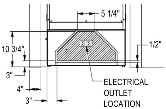
Installation must comply with all applicable electrical codes. The electrical supply must be located within the shaded area of the illustration below. A separate circuit, servicing only this appliance, is required. A ground fault circuit interrupter (GFCI) is not recommended and may cause interruption of operation. The outlet should be placed in the hatched area dimensioned below.
| Electrical Supply 115V | , 60Hz, 1 Phase, 3.2 Amps |
| Service Dedicated 15 | amp circuit |
| Power/Cord Type/Length | NEMA 5-15 Cord Plug Type(5' length) |
NOTICE
This product contains blown foam insulation
using blowing agent R-611 (Methyl Formate). The foam in this product does not contain HFC's, CFC's, or HCFC's.
INSTALLATION
PRIOR TO INSTALLATION
CAUTION
Before beginning installation,
carefully inspect the cabinet for hidden damage. If damage is discovered, immediately file a claim with the transportation company. Perlick is not responsible for damage in transit.
CAUTION
When moving the unit, be sure to flooring with appropriate material to om moving the appliance.
CAUTION
If the unit has been laid on its back or sides, place unit upright and allow minimum of 24 hours before connecting the unit. Failure to do so can affect the function and performance of the appliance.
CAUTION
This appliance should be installed in dry, ventilated indoor location. The ambient temperature of the location must be between 55^ F ( 13^ C) and 100^ F ( 43^ C) for optimal performance.
CAUTION
This product must be installed on a level floor for safety and optimal performance. The base must be flat to ensure anti-tip brackets properly function and that the refrigeration system is level. Any walls and surrounding furniture/fixtures need to be securely attached to the floor, wall studs or concrete prior to installation of the column.
CAUTION
To ensure proper performance, the air intake (toe kick) must not be blocked. Perlick refrigeration is front-breathing — covering the intake will cause the system to overheat and fail.
CAUTION
Perlick column doors open to 105°. When installing a panel thicker than 34 " (19), or if located next to adjacent wall, the 90^ hinge stop pin may be required to prevent damage to the unit and adjacent cabinetry/walls. This hinge pin must be installed prior to full integration.
In addition, the appliance must not be in direct exposure of constant sunlight or excessive heat. If it must be installed next to a heat source, such as a cooking appliance or radiant heat, you must install an insulating plate between the column and heat source.
When fully stocked, Perlick column refrigeration is very heavy. To ensure the safety and prevent home damage, the load-bearing capacity of your floor must be 846 lbs (384 kg).
INSTALLATION TOOLS AND MATERIALS
- Screwdrivers (standard and #2 Phillips)
- Power drill
- Needle nose pliers
- Drill bits
- 13mm socket or wrench set
- 2' and 4' levels
- Material to protect flooring and surrounding cabinetry
OPENING DIMENSIONS - SINGLE UNIT
The depth of each Perlick column is 24" (610).
Allow for panel thickness when planning the finished opening depth. A minimum of a 4" (102) finished return is required on all sides of the opening. See page 6 for niche and product dimension drawings.
It is important that the side walls of the niche are plumb prior to installation. The minimum thickness of both the side walls and the top wall must be 5/8" (16). A thickness of 3/4" (19) is recommended for toe kick panels.
Framed cabinets will require additional finished filler material behind the face frame for a proper installation. Refer to the illustration on page 6.
OPENING DIMENSIONS - TWO UNITS
When installing two units side-by-side, a Perlick Dual Installation Kit (part number CR-ACC-D1) is required. You must plan for both units plus dual installation kit when planning the cut-out dimensions.
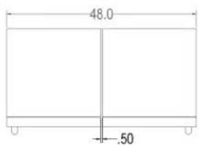
The cutout width for a dual CR24 installation is 48". The cutout width for a dual installation consisting of one CR24 and one CR30 is 54-1/2". For more information, see instructions that accompany the CR-ACC-D1.
natural_image
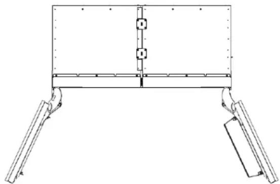
Technical line drawing of a mechanical support frame with two vertical supports and a central vertical component (no text or symbols)INSTALLATION CONTINUED
ADJACENT WALL OR STRUCTURE MINIMUM CLEARANCE REQUIREMENTS
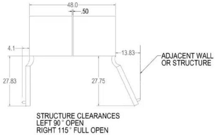
When building into structure or next to adjacent walls reference this drawing for minimum required clearances to avoid interference when opening the door(s).
The adjacent structure clearances indicated are based on a standard perlick handle installed on the door overlay.
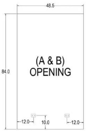
MINIMUM SPACING REQUIRED BETWEEN ADJACENT CABINETS TO AVOID DOOR SWING INTERFERENCE.
(A) 2 Cabinets HANDLE TO HANDLE.
Refer to (A&B) Opening diagram (page 8) for finished opening dimensions and outlet locations.

(A) HANDLE TO HANDLE
(B) 2 Cabinets HINGE TO HINGE.
Refer to (A&B) Opening diagram (page 8) for finished opening dimensions and outlet locations.
(B) HINGE TO HINGE
INSTALLATION CONTINUED
MINIMUM SPACING REQUIRED BETWEEN ADJACENT CABINETS TO AVOID DOOR SWING INTERFERENCE CONTINUED.
Opening Dimensions
(C) 2 Cabinets HANDLE TO HINGE.
Refer to (C) Opening diagram (page 8) for finished opening dimensions and outlet locations.
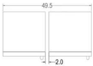
(C) HANDLE TO HINGE
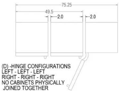
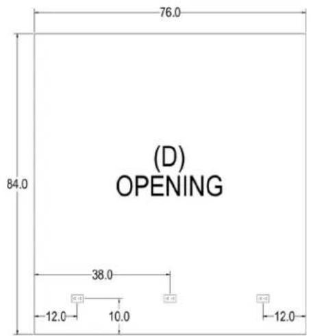
(D) 3 Cabinets with Hinges either all left or all right.
Refer to (D) Opening diagram (page 8) for finished opening dimensions and outlet locations.
(E) 3 Cabinets with Hinges Left-Right-Left or Right-Left-Right.
Refer to (E) Opening diagram (page 9) for finished opening dimensions and outlet locations.

(E) - HINGE CONFIGURATIONS
LEFT - RIGHT - LEFT
RIGHT - LEFT - RIGHT
ALL CABINETS PHYSICALLY
JOINED TOGETHER
(F) 3 Cabinets with Hinges Left-Left-Right or Right-Right-Left.
Refer to (F) Opening diagram (page 9) for finished opening dimensions and outlet locations.
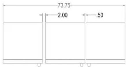
(F) - HINGE CONFIGURATIONS
LEFT - LEFT - RIGHT
RIGHT - RIGHT- LEFT
(2) CABINETS PHYSICALLY JOINED TOGETHER
INSTALLATION CONTINUED
MINIMUM SPACING REQUIRED BETWEEN ADJACENT CABINETS TO AVOID DOOR SWING INTERFERENCE CONTINUED.
(G) 3 Cabinets with Hinges Right-Left-Left or Left-Right-Right.
Refer to (G) Opening diagram (page 9) for finished opening dimensions and outlet locations.
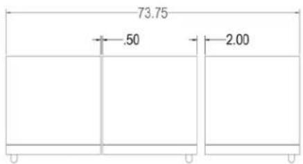
(G) - HINGE CONFIGURATIONS
RIGHT - LEFT - LEFT
LEFT - RIGHT - RIGHT
(2) CABINETS PHYSICALLY JOINED TOGETHER
FINISHED OPENING DIMENSIONS FOR 2 AND 3 UNIT INSTALLATIONS.

INSTALLATION CONTINUED
FINISHED OPENING DIMENSIONS FOR 2 AND 3 UNIT INSTALLATIONS CONTINUED.


Note:
For installations involving more than 3 cabinets, combine opening dimensions for the openings which correspond to the combined Hinge and Handle configurations.
INSTALLATION CONTINUED
![84" [2134] 25" [635] A](/content/2026/06/1229349/images/53a937b8c5335059738862db2f9e26a2a388c33f6e14abbe56e7b63d5255ec65.jpg)
PLEASE NOTE: When installing column adjacent to wall, a 2" clearance is required if door is opening towards the wall
![24 3/4" [629] 24" [610] OVEALL TO FRONT OF DOOR FRAME B 3/4" [19] OVERLAY 83 7/8" [2131] OVERALL 22 1/8" [562] TO CABINET 4" [102] TO 6" [153] TOE KICK 21 9/16" [547] TO GRILL](/content/2026/06/1229349/images/e7d503f91ad289ad923fc4ef2321baa027b107ecefe66179ed6bab01861c936c.jpg)
![SIDE WALL CABINET DOOR A FRAME FACE 4" [102]](/content/2026/06/1229349/images/4bf795fe14f07374b46b005deb562c51343b7a25006649799746842597bde5c0.jpg)
| A | |
| CR24, CC24 24" (610) | |
| CR30, CC30 30" (762) |
| B |
| CR24, CC24 23 -3/4" (604) |
| CR30, CC30 29-3/4" (756) |
INSTALLATION CONTINUED
ELECTRICAL
▲DANGER ocution hazard.
Electrical grounding is required. This appliance is equipped with a 3-prong (grounding) polarizing plug for your protection against possible shock hazards. Failure to comply with these electrical guidelines may result in possible death or serious injury, fire or loss of property.
⚠ WARNING Never use an extension cord to connect unit to electrical source. Do not use a two-prong adapter or remove the power cord grounding prong.
Installation must comply with all applicable electrical codes. The electrical supply must be located within the shaded area of the illustration below. A separate circuit, servicing only this appliance, is required. A ground fault circuit interrupter (GFCI) is not recommended and may cause interruption of operation. The outlet should be placed in the hatched area dimensioned below.
| Electrical Supply 115V, 60Hz, 1 Phase, 3.2 Amps | |
| Service Dedicated 15 amp circuit | |
| Power/Cord Type/Length | NEMA 5-15 Cord Plug Type(5' length) |
PLACEMENT
CAUTION Before moving unit into position, secure the door closed and protect any finished flooring.
Use an appliance dolly to move the unit near the opening.
ANTI-TIP BRACKET
⚠ WARNING To prevent the unit from tipping forward, the anti-tip bracket must be installed. Use all anti-tip bracket hardware as instructed. Level as instructed on page 12 prior to installing anti-tip bracket(s)
The anti-tip bracket and supporting hardware is included with your unit. Please note that four anti-tip brackets are required for each unit or dual installation. In the case of dual installation, each individual unit must be outfitted with the two anti-tip brackets on cabinet sides for a total of four.
For drawings of the anti-tip bracket installation on integrated (built-in) units, see page 13. For drawings of the anti-tip bracket installation on freestanding units, see page 14.
⚠ WARNING Verify there are no electrical wires or plumbing in the area which the screws could penetrate.
⚠️ CAUTION Always wear safety glasses and use other necessary protective devices or apparel when installing or working with anchors. Anchors are not recommended for use in lightweight masonry material such as block or brick, or for use in new concrete which has not had sufficient time to cure. The use of core drills is not recommended to drill holes for anchors.
90° HINGE STOP
Perlick column doors open to 105°. When installing a panel thicker than 34 " (19), or if located next to adjacent wall, the 90° hinge stop pin may be required to prevent damage to the unit and adjacent cabinetry/walls. This hinge pin must be installed prior to full integration.
-
Remove the cabinet hinge trim cover by removing the three Phillips head fasteners located on the top of the cabinet. Lift the rear of trim cover to tilt trim cover to disengage tab on right and left end of trim cover. Slide forward to remove.
-
Open cabinet door approximately 45^ to 85^ to expose hole under hinge guard. Install hinge pin into hole. Ensure hinge pin is fully seated to top of hinge to prevent damage to hinge guard.
-
Reattach the cabinet hinge trim piece. Slide front bottom of hinge trim cover under reed switch. Tilt trim cover to engage right and left end tab into cabinet. Install the three fasteners.
PLACEMENT & ALIGNMENT
CAUTION
Before moving the unit into position, secure the
door closed and protect any finished flooring.
WARNING
If the unit has been on its back, it must stand
upright for a minimum of 24 hours before connecting power.
Move the unit near the opening. Plug the power cord into the grounded outlet and roll the unit into position. Push unit into place.
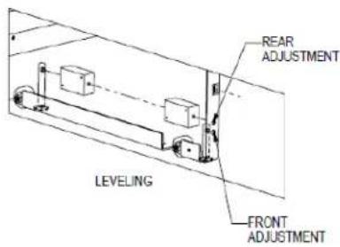
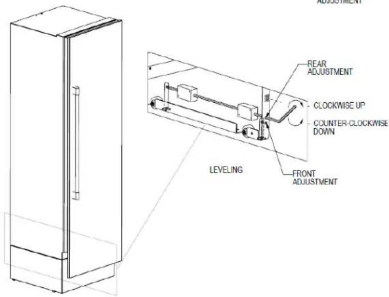
LEVELING
Front and rear leveling legs can be adjusted from the front once the unit is positioned.
NOTE: Remove grill to access leveling adjustment access holes.
Once the unit is in position, height adjustment can be made from the front. Using the hex driver leveling tool, turn clockwise to raise the unit or counterclockwise to lower. Refer to the illustration below.
When the unit is properly leveled, door adjustments are less likely to be necessary.
CAUTION
Level the unit to the floor, not surrounding
cabinetry. This could affect the operation of the unit, such as door closing.
WARNING
To reduce the possibility of the unit tipping
forward, the front leveling legs must be in contact with the floor.

natural_image
Interior view of a workshop or lab space with a person standing near a large electronic device (no visible text or symbols)Adjusting front leveling legs.
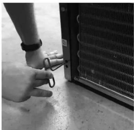
natural_image
Close-up of a hand holding a small metal clip next to a large heating element (no visible text or symbols)Adjusting rear leveling legs.
LEVELING THE UNIT
ANTI-TIP BRACKET
The anti-tip bracket and supporting hardware is included with your unit. In the case of dual installation, each individual unit must be outfitted with the included anti-tip brackets.
For drawings of the anti-tip bracket installation on integrated unit, see below. For drawings of the anti-tip bracket installation on freestanding units, see page 11.
WARNING
Verify there are no electrical wires or
plumbing in the area which the screws could penetrate.
CAUTION
Always wear safety glasses and use other
necessary protective devices or apparel when installing or working with anchors. Anchors are not recommended for use in lightweight masonry material such as block or brick, or for use in new concrete which has not had sufficient time to cure. The use of core drills is not recommended to drill holes for anchors.
Anti-Tip Bracket Installation for Built-In Applications
NOTE: Do not fasten anti-tip brackets to adjacent cabinetry until the cabinet has been leveled.

ANTI-TIP APPLICATION
Anti-Tip Application for Freestanding Applications
NOTE: Cabinet must be leveled before securing to wall with anti-tip bracket.

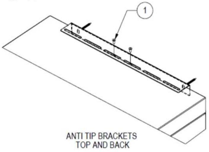
![WALL 1 1/2" [38] ANTI TIP BRACKET TOP AND BACK DETAIL D SCALE 1 : 3](/content/2026/06/1229349/images/aa9189312ac73e4fd337ba63c09f37d48c42728a54c17c50c079755078f78791.jpg)
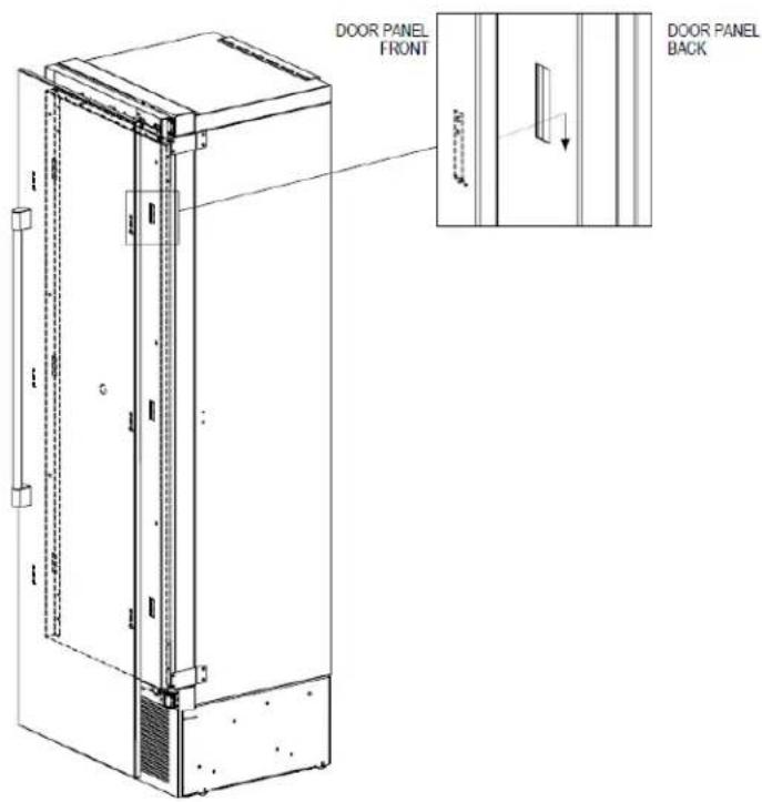
INSTALLING DOOR OVERLAY PANELS
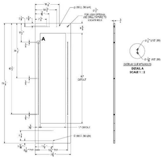
Typical panel dimensions are based on 84"
(2134) finished height with 1/8" (3) reveals.
Template must be adjusted for panels exceeding typical dimensions.
Place the panel face down on a protected work surface. Attach six clips to the back of overlay in locations indicated in wood overlay drawing.
Use provided #10 x 1/2" screws to attach clips to overlay. Overlay then slides onto door face. Attach overlay to door adjustment brackets using remaining #10 x 1/2" screws. Once mounted, adjust overlay to match adjacent cabinetry.
CAUTION
As the reveal between cabinets and the unit
decreases, the potential exists for severe finger pinching if fingers are placed in the opening when door is closing.
4" Toe Kick Wood Overlay Template Glass Door
INSTALLING DOOR OVERLAY PANELS CONTINUED
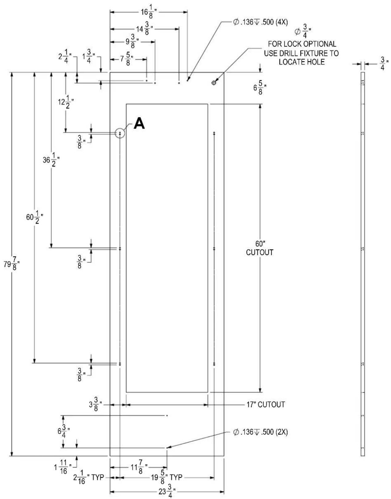
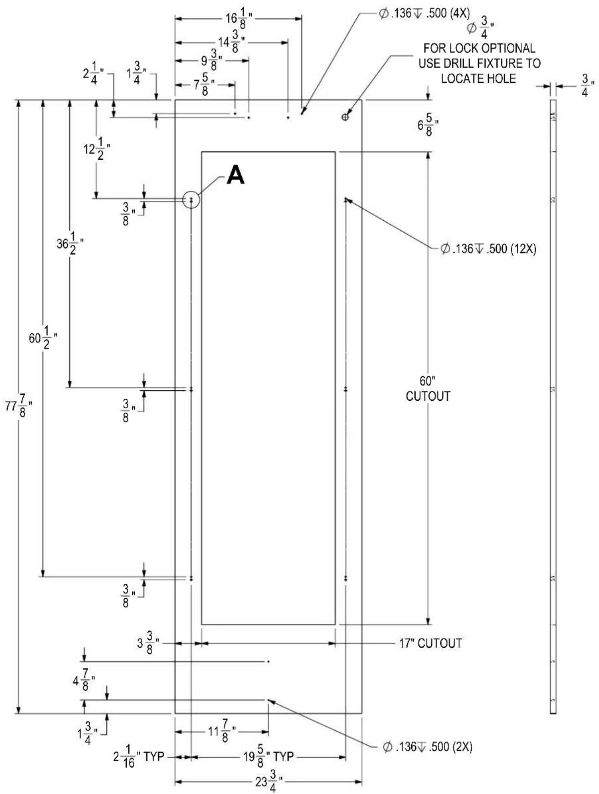
Custom Overlay Panels
A custom door panel and handle hardware must be installed if a customer chooses to not purchase a Perlick stainless steel door panel. The thickness of the custom panel can vary. A minimum 5/8" (16) thick panel is required, but the thickness can be increased provided it does not exceed the maximum panel weight of 65 lbs (29). 3/4" panel is recommended. Please note that the combined door and overlay weight cannot exceed 120 lbs (54). The depth of each model is 24" (610). Allow for panel thickness when planning the finished opening depth. Templates for glass doors with 4" or 6" toe kicks can be found starting on page 17.
CAUTION
As reveals between cabinetry and the unit
decrease, severe finger pinching can occur while the door is closing.
The height of the custom door panel can extend beyond the typical panel height provided it does not exceed the weight limit listed above.
CAUTION
Do not install a solid overlay panel onto the
front of a glass door model. Condensation will form between the glass and the overlay panel, which will cause damage to custom cabinetry.
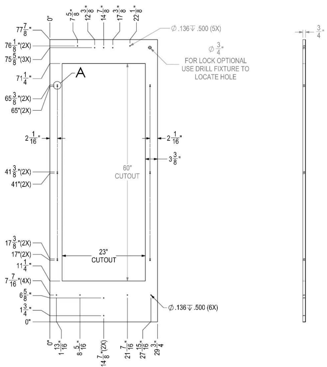
24 INCH COLUMN GLASS DOOR TEMPLATE FOR 4" TOE KICK
24 INCH COLUMN GLASS DOOR TEMPLATE FOR 6" TOE KICK
30 INCH COLUMN GLASS DOOR TEMPLATE FOR 4" TOE KICK

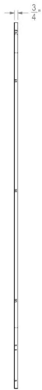
30 INCH COLUMN GLASS DOOR TEMPLATE FOR 6" TOE KICK
24" WINE SHELF FRONT DETAIL

30" WINE SHELF FRONT DETAIL
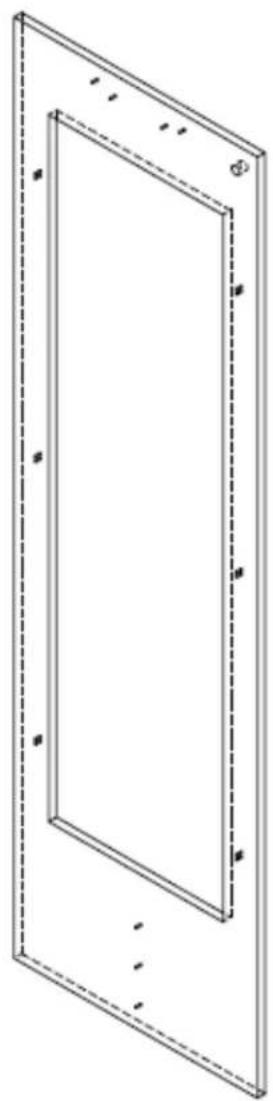
DOOR OVERLAY PANEL ADJUSTMENT
Close the door to make adjustments to align panels and reveals.
For up-and-down adjustments, turn the height adjustment screws in the top bracket in and out. Adjust the screws as needed to achieve an even reveal on each side of the door overlay.
Once final adjustments are made to the position of the door overlay, secure the overlay in place by installing the bottom overlay bracket as shown in BOTTOM OF DOOR illustration below.
TOP OF DOOR
natural_image
Technical line drawing of a rectangular frame with mounting brackets and internal components (no text or symbols)
BOTTOM OF DOOR

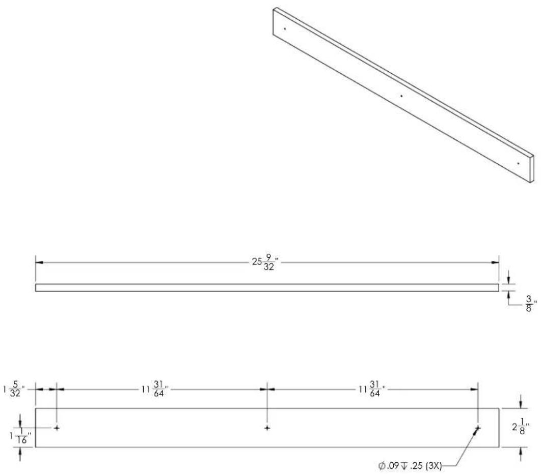
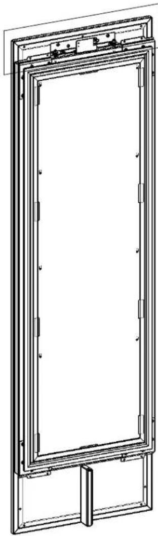
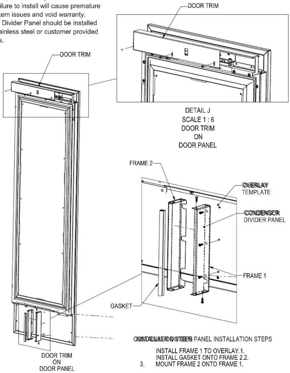
DOOR TRIM INSTALLATION
Once overlay is adjusted, mount the door trim cover onto the door adjustment bracket using the provided screws.
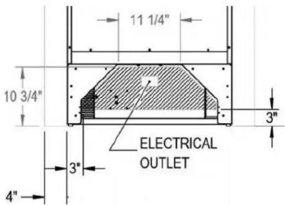
NOTICE
Installation of Condenser Divider Panel on bottom
of door panel, is critical to performance of the system. Failure to install will cause premature sealed system issues and void warranty. Condenser Divider Panel should be installed to either stainless steel or customer provided door panels.
SCREW ZONE FOR 24 AND 30 INCH OVERLAY TEMPLATES
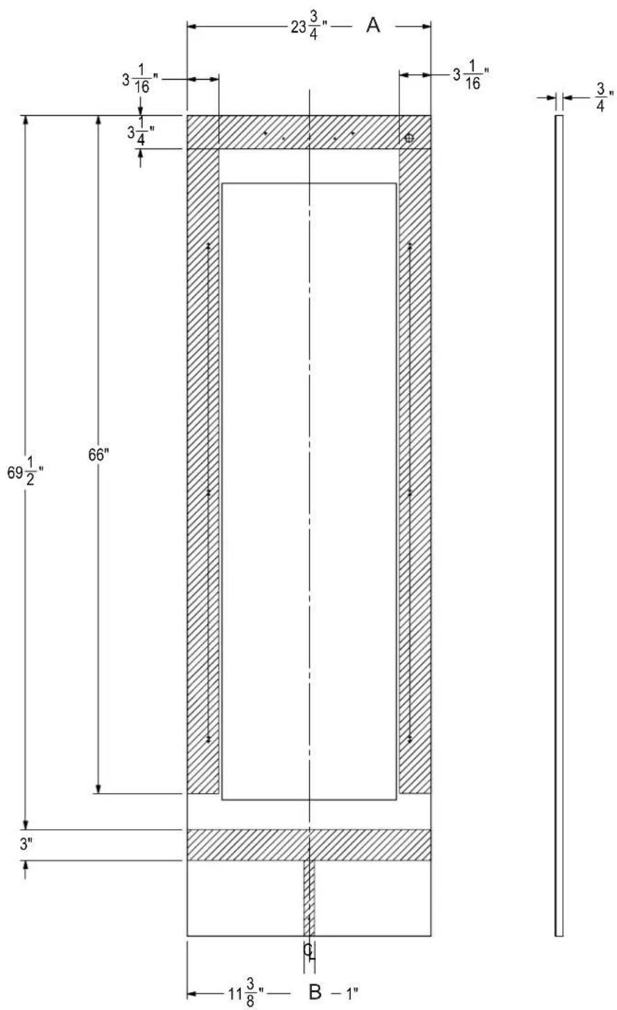
natural_image
Pure technical line drawing of a rectangular frame with dashed lines indicating hidden edges (no text or symbols)NOTE: HATCH AREAS SHOULD PROVIDE ENOUGH THICKNESS FOR WOOD SCREWS FOR OVERLAY ATTACHMENT BRACKET.
| A | |
| CR24, CC24 | 23-3/4” |
| CR30, CC30 | 29-3/4” |
| B | |
| CR24, CC24 | 11-3/8" |
| CR30, CC30 | 14-3/8" |
WINE STORAGE
Wine Shelving
- Prior to making shelf adjustments, clear the shelf of product. Shelf must be empty prior to changing its position.
To Remove Wine Shelves

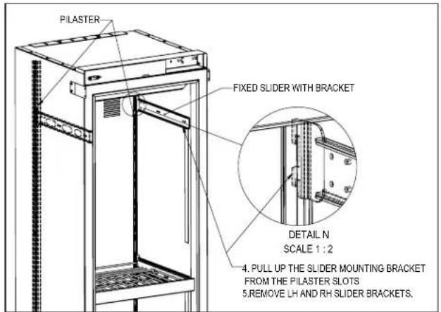
To Install Wine Shelves


WINE STORAGE
To Remove Wine Shelf Fronts To Remove Wine Shelf Plugs
- Use a #2 Phillips screwdriver to remove the two screws on either side of the wine shelf front as pictured.

natural_image
Close-up of a computer drive with a red circular annotation highlighting a key component (no text or symbols visible)- Remove shelf plugs prior to the removal of shelving. Use a needle nose pliers to grab onto the rubber plug and wiggle until plug is free.

natural_image
Close-up of a hand using red-handled tool to adjust or install a metal panel (no visible text or symbols)
natural_image
Close-up of a hand using red pliers to clean or store metal panels (no text visible)COMPLETION - TOE KICK INSTALLATION
Install the toe kick by snapping into latch catches.

TOE KICK CLEARANCE
![24 3/4" [829] OVER ALL 3/4" [19] OVERLAY 24" [610] TO FRONT OF DOOR FRAME DOOR PANEL 83 7/8" [2130] TO CABINET BASE TOE KICK CLEARANCE 24" [610] TO BACK OF UNIT HINGE DOOR PANEL LOUVERS FOR VENTS 4" [102] TO](/content/2026/06/1229349/images/14a83bfaf492f20ca0641ef464c9fb8072e469e62a5df34f637581783160558a.jpg)
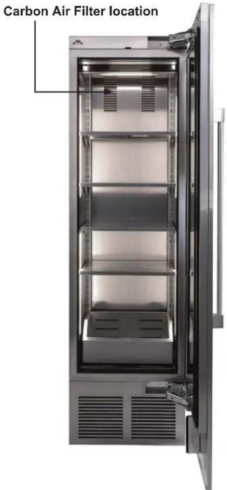
INSTALLING AIR FILTERS
Carbon Air Filter
The carbon air filters should be placed on the perforated panel located in the top-rear of the cabinet.
NOTE: For units with shelves the top shelf will need to be removed for filter.
- Remove the filter from the plastic bag before installing into the unit. Do not open or puncture the Tyvek® bag. For units with wine shelves the top shelf will need to be removed for filter.
- To lower the carbon air filter panel, pull firmly.
- Place the carbon air filter directly onto the panel and close panel - push firmly to engage closure clips.
- It is recommended that the carbon filter be replaced every 6 months.

natural_image
Close-up of a metallic industrial machine with perforated metal panel and slatted base (no visible text or symbols)Carbon Air Filter Panel (closed)
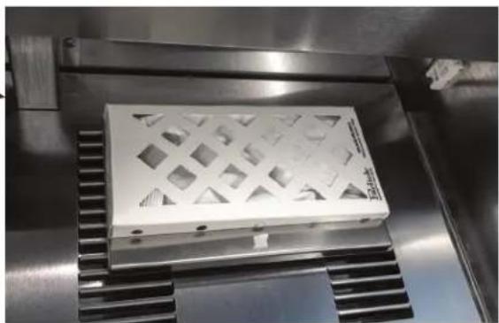
natural_image
Close-up of a metallic industrial component with a lattice-patterned casing, placed on a metal workbench (no visible text or symbols)Carbon Air Filter with panel opened
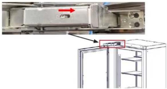
HINGE SOFT CLOSE ACTIVATION INSTRUCTIONS
With a 1/4-inch drive T20 Torx bit socket, activate both hinges by turning the screw in the center of the hinge from "0" to "1." This allows will allow the door to self close once 15 degrees.
natural_image
Technical diagram of a refrigerator interior showing internal components and a close-up view of the front panel (no text or symbols present)COLUMN DIGITAL CONTROL OPERATION
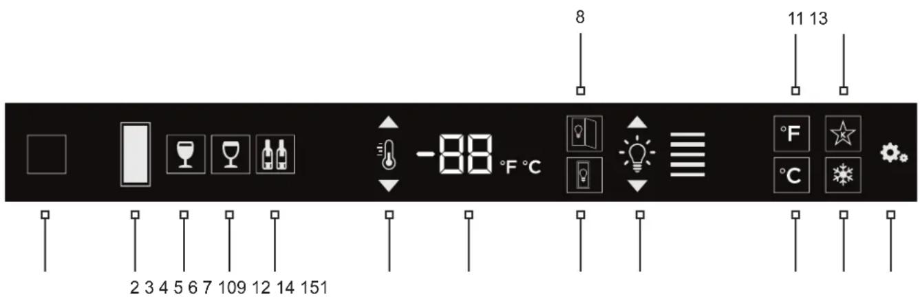
1 Wake Button
2 Temperature zone selection (Dual-zone models)
3 White wine temperature setting (wine models only)
4 Red wine temperature setting (wine models only)
5 Cellar temperature setting
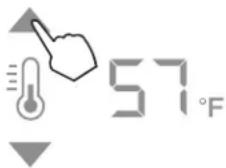
6 Temperature adjustment (up and down in 1^ increments)
7 Temperature readout
8 Light adjustment (door open)
9 Light adjustment (door closed)
10 Light intensity adjustment
11 Fahrenheit temperature mode
12 Celsius temperature mode
13 Sabbath mode
14 QuickCool mode
15 Settings menu
Using the Wine Column Control
Upon door opening, the Wake button (1) outline will illuminate. Once activated, the temperature zone selection (2), temperature adjustment (6), temperature readout (7) and settings (15) menu icons will illuminate.
Selecting a Temperature Zone
Perlick's PerlIQ™ digital controller is preset with recommended temperature settings for white wine, red wine and cellaring. Within the presets, you have the ability to adjust the temperature in 1° increments as you desire. Because single zone models are one temperature throughout, there is no zone selection. On dual zone models, press the temperature zone selection (2) icon to toggle through the zones until desired zone is illuminated.

Top Zone
Bottom Zone
NOTE: Dual Zone Wine Upper compartment temperature set point must always be set at or above the lower compartment set point.
COLUMN DIGITAL CONTROL OPERATION
Storing White Wine
Perlick wine columns are preset with expert-recommended temperature settings for white wine. To set a zone in dual zone models to this preset, touch the temperature zone selection icon (2) to illuminate the zone you'd like to set to white wine temperature, then choose the white wine temperature setting icon (3) to set. For single zone models, simply choose the white wine temperature setting icon (3).
| Compartment | Sp. Factory Setting | Temperature Range |
| Any 50°F 40°F | -68°F |

To adjust the temperature up or down, press the temperature adjustment (6) arrows until desired temperature is reflected in the temperature readout (7). Double beep indicates that minimum or maximum temperature has been reached. Temperature will flash twice to indicate new setting.
Storing Red Wine
Perlick wine columns are preset with expert-recommended temperature settings for red wine. To set a zone in dual zone models to this preset, touch the temperature zone selection icon (2) to illuminate the zone you'd like to set to red wine temperature, then choose the red wine temperature setting icon (4) to set. For single zone models, simply choose the red wine temperature setting icon (4).
| Compartment | Sp. Factory Setting | Temperature Range |
| Any 60°F 40°F | -68°F |

To adjust the temperature up or down, press the temperature adjustment (6) arrows until desired temperature is reflected in the temperature readout (7). Double beep indicates that minimum or maximum temperature has been reached. Temperature will flash twice to indicate new setting.
Cellaring Wine
Perlick wine columns are preset with expert-recommended temperature settings for cellaring (long-term storage) wine. By choosing the cellar mode, the entire cabinet will default to 55^ F for long-term storage. For dual zone models, touch the temperature zone selection icon (2) to illuminate, then choose the Cellar temperature setting icon (5) to set. For single zone models, simply choose the Cellar temperature icon (5).
| Compartment | Sp. Factory Setting | Temperature Range |
| Any 55°F 40°F | -68°F |
To adjust the temperature up or down, press the temperature adjustment (6) arrows until desired temperature is reflected in the temperature readout (7). Double beep indicates that minimum or maximum temperature has been reached. Temperature will flash twice to indicate new setting.
Column Theatre Lighting
Perlick column wine reserves feature an impressive amount of lighting for clear viewing and display of wine bottles. Main lighting, which can be changed from white to blue, runs vertically down the wall, and display lighting runs horizontally across the ceiling of the unit. Dual zone models also have display lighting on ceiling of the lower zone.

natural_image
Two icons showing a hand pointing at a lightbulb and a light bulb with arrows, above horizontal lines (no text or symbols)Wine models are factory set to white lighting. To adjust the brightness of the lighting when the door is opened, press the up and down arrows in the light intensity adjustment icon (4). To change to blue lighting, continue pressing the arrows until the control turns blue in color. To return to white lighting, continue pressing the arrows until controls illuminate white. Icons will flash twice to confirm color setting.
COLUMN DIGITAL CONTROL OPERATION
Changing from Fahrenheit to Celsius scale
The controller is factory set to Fahrenheit scale, but can easily be changed to read Celsius in the settings menu.

Press the settings menu (15) icon on the far right. This will illuminate a cluster of four icons as shown to the left. To display temperatures in Celsius, press the Celsius readout icon (12).
Change will be reflected in the temperature readout (7). The C will be illuminated to signify the scale.
Sabbath Mode
All Perlick column refrigeration models have Sabbath mode capabilities. This allows the user to interact with the unit without changing the amount of energy it is using. In this mode, the interior lighting is turned off until user turns off Sabbath mode.
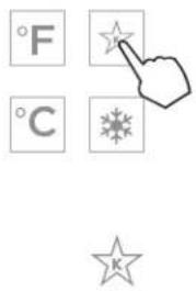
Press the settings menu (15) icon on the far right. This will illuminate a cluster of four icons as shown to the left. To activate Sabbath mode, press the Sabbath mode icon (13).
Please note that, when in Sabbath mode, the Sabbath mode (13) icon will be the only icon that will be illuminated (continuously) until user presses the Sabbath mode icon to turn the mode off.
Quick Cool (Shopping) Mode
The wine column can be set to Quick Cool (shopping) mode to lower the temperature after loading a large quantity of product to quickly bring them to the preferred temperature.
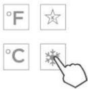
Press the settings menu (15) icon on the far right. This will illuminate a cluster of four icons as shown to the left. To activate Quick Cool (shopping) mode, press the Quick Cool (14) icon. This will activate the mode and the Quick Cool (14) will remain illuminated until the set point is achieved.
Showroom Mode
Select Showroom mode for units that are being used solely for display purposes. Showroom mode has the user interface fully functional along with the cabinet lights, however, no compressor, evaporator fans or condenser fans will operate.
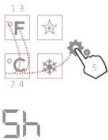
Press the settings menu (15) icon on the far right. This will illuminate a cluster of four icons as shown to the left. A 5 key combination*, including the Fahrenheit readout (11) icon, Celsius readout (12) icon and settings menu (15) icon, will activate Showroom mode: F-C-F-C-Settings. Upon activating showroom mode, the temperature readout (7) with show "Sh" each time the door is opened until showroom mode is turned off.
To exit showroom mode, enter the 5 key combination.
*5 key combination must be completed within 5 seconds to turn showroom mode on and off.
STAINLESS STEEL CLEANING
Perlick's stainless steel surfaces are food grade, 304 stainless steel. Stainless steel is a "passive" metal because it contains other metals like Chromium, Nickel and Manganese that stabilize the atoms. Chromium provides an invisible film that covers the steel surface, acting as a shield agent against corrosion. As long as the film is intact and not contaminated, the metal is passive and stainless. If the passive film of stainless steel has been broken, the surface can start to corrode or rust.
Three materials or processes can break down stainless steel's passive layer, allowing corrosion to occur.
- Mechanical Abrasion
This refers to items that will scratch stainless steel surfaces. Steed pads, wire brushes and scrapers are prime examples.
- Water
Water that comes out of the faucet in varying degrees of hardness. Hard water may leave spots. When allowed to sit, these deposits will break down the passive Chromium layer and rust stainless steel. Other deposits from food preparation must be promptly removed with an appropriate cleaning agent.
- Chlorides
Chlorides are found everywhere. They are in water, food and table salt. Household and industrial cleaners are the worst offenders.
Preventing Stainless Steel Rust
Use non-abrasive tools to clean stainless steel surfaces. Soft cloths and plastic scouring pads will not harm the steel's passive layer.
Clean with polish lines. Some stainless steels have visible polishing lines or "grain". When visible lines are present, always scrub in a motion parallel to the lines. When the grain cannot be seen, polish in a consistent straight pattern - not in a circular motion.
Use alkaline, alkaline chlorinated or non-chloride containing cleaners. While many traditional cleaners are loaded with chlorides, the industry is providing
an ever-increasing choice of non-chloride cleaners. If you are not sure of chloride content in the cleaner being used, contact your cleaner supplier. If you present cleaner contains chloride, ask your supplier for an alternative. Avoid cleaners containing quaternary salt; it also can attack stainless steel and cause pitting and/or rusting. Clean frequently to avoid build-up of hard, stubborn stains.
Stainless Steel Exterior Door Cleaning
Keep exterior stainless steel surface pristine by wiping the door with a damp microfiber cloth, followed by a dry polishing chamois. Always follow the grain direction when cleaning.
Glass Cleaning
Perlick's triple pane glass is designed to protect cabinet contents from UV light, while displaying the contents elegantly while the door is closed. To ensure life long performance, always use standard glass cleaners containing alcohol to clean the acid-etched glass. Never use products containing hydrofluoric acid, fluorine, chlorine or ammonia derivatives because they can damage the surface of the glass. Never use acidic and alkaline products as they can abrade the glass surface.
AIR FILTRATION
We recommended changing the air filters every 6 months for optimum performance. Filters can be purchased through your local authorized Perlick dealer.

natural_image
Close-up of a metallic industrial machine with a white plastic tray and ventilation grilles (no visible text or symbols)Carbon Air Filter
The Carbon air filter removes odor, bacteria and mold spores from the air. To remove the Carbon air filter in all units, refer to page 29 - carbon air filter.
TROUBLESHOOTING
If the unit appears to be malfunctioning, check the troubleshooting guide below to see if you can identify the cause and remedy for the issue and resolve it without a service call.
| Problem Cause Solution | ||
| UI flashes Cabinet is in Showroom Mode | Press the settings menu icon (💡) to illuminate a cluster of four icons. A five key combination - F-C-F-C-Settings - will exit showroom mode as shown below: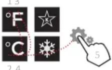 | |
| Door alarm is beeping | Door has been open for more than 3 minutes | Close the door |
| Light stays on when door is closed (wine units) | Door Closed with Light (Display) | Follow directions above to turn off Door Closed with Light (Display) mode. |
| Light stays on when door is closed (all units) | Door not closing correctly | Determine what may be causing the door to not fully close |
| Issue with reed switch and magnet | Contact Perlick Technical Service at (844) 411-8050 | |
| Compartments are warmer than usual | Control is preset too warm | Lower the set point temperature. Refer to changing the set point for the specific model in this manual |
| Condenser is dirty or obstructed Clear the condenser and clear obstruction | ||
| The door is open or has been opened more frequently lately | Wait 24 hours and recheck the temperature | |
| Internal louvers and/or damper covers are obstructed | Reset the preset temperature if necessary - refer to page 30 of this manual for settingsMake sure the louvers and/or the fan are not obstructed | |
| Warm product was recently placed in the cabinet | Engage QuickCool mode; see pages 32 for instructions for instructions on how | |
| System runs for a long period of time | Condenser is dirty or obstructed Clean the condenser and clear the obstruction | |
| Door was kept open for a long time or was opened more frequently, or warm product was recently placed in the cabinet | Wait 24 hours and recheck temperature | |
| Hot day and warm room temperature Normal for the system to run more frequently | ||
| Condensation forms outside of the unit | High humidity and/or frequent door opening | Condensation is normal in high humidity ambient, if installed next to another Perlick column, ensure proper dual-installation kit has been selected |
| Condensation forms inside the compartments | Door is not closing and sealing properly | Make sure the door is closing properly.Check the door deal and replace if necessaryIf condensation persists, contact Perlick Technical Service at (844) 411-8050 |
TROUBLESHOOTING
| Noisy operation | Soft sounds from compressor, fan motor and valves heard | Normal operation |
| “Crackling” sounds during defrost Normal operation | ||
| Unit is not running No power going to the unit | Home circuit breaker was tripped. Reset the circuit breakerEnsure the unit is plugged inEnsure the unit is not in “Showroom” mode | |
Below is a list of column troubleshoot codes. If the cause occurs, the corresponding code will flash on the PerlIQ™ touch-screen control. See the Solution column on the far right for the corrective action.
| Code Cause Solution | ||
| P1, P2, P3, P4, P5, P6 Temperature or humidity sensor failure | Call Perlick Technical Service at (844) 411-8050 | |
| L1, L2, L3, L4, L5, L6 Low temperature alarm | High and Low temperature alarms may occur from extended door openings or heavy loading of warm product. If alarm persists, call Perlick Technical Service at (844) 411-8050 | |
| H1, H2, H3, H4, H5, H6 High temperature alarm | ||
| r5, r6 Open/Disconnected humidity sensor | Call Perlick Technical Service at (844) 411-8050 | |
| d1 Door open alarm Close the door | ||
COLUMN INSTALL CHECKLIST
-
Is the unit level?
-
Is the 90 degree hinge stop installed? Only needed for installations with potential handle interference on hinge side.
-
Is anti-tip bracket installed and properly engaged?
-
Are all 6 clips engaged on door panel and bottom overlay bracket installed?
-
Is the condenser divider installed at bottom of door panel?
-
Is the top door trim installed?
-
Is the toe kick installed?
-
Is the carbon air filter installed and panel closed securely?
-
Has the hinge soft close feature been activated?
-
Has shipping material been removed from cabinet and shelf plugs removed from pilasters?
-
Has the inside of cabinet been wiped clean of any packaging or other debris?
-
Has all of the packaging been removed from customer site?
natural_image
Exterior view of a modern stainless steel beer refrigerator with open doors showing glass doors (no visible text or symbols)
8300 West Good Hope Road, Milwaukee, WI 53223, USA
perlick.com • (800) 558-5592


- Installation & Operation Manual
- Column Refrigeration
- TABLE OF CONTENTS
- GENERAL INFORMATION
- Introduction
- Product Information
- Warranty Registration
- Product Identification Plate
- SAFETY
- IMPORTANT!
- ! WARNING: California Prop 65 Notice
- SITE PREPARATION
- PRIOR TO INSTALLATION
- Safety Precautions
- WARNING
- CAUTION
- DANGER
- Electrical
- NOTICE
- INSTALLATION
- INSTALLATION TOOLS AND MATERIALS
- OPENING DIMENSIONS - SINGLE UNIT
- OPENING DIMENSIONS - TWO UNITS
- INSTALLATION CONTINUED
- ADJACENT WALL OR STRUCTURE MINIMUM CLEARANCE REQUIREMENTS
- MINIMUM SPACING REQUIRED BETWEEN ADJACENT CABINETS TO AVOID DOOR SWING INTERFERENCE.
- 2 Cabinets HANDLE TO HANDLE.
- 2 Cabinets HINGE TO HINGE.
- MINIMUM SPACING REQUIRED BETWEEN ADJACENT CABINETS TO AVOID DOOR SWING INTERFERENCE CONTINUED.
- FINISHED OPENING DIMENSIONS FOR 2 AND 3 UNIT INSTALLATIONS CONTINUED.
- Note:
- ▲DANGER ocution hazard.
- PLACEMENT
- ANTI-TIP BRACKET
- 90° HINGE STOP
- PLACEMENT & ALIGNMENT
- LEVELING
- LEVELING THE UNIT
- Anti-Tip Bracket Installation for Built-In Applications
- ANTI-TIP APPLICATION
- Anti-Tip Application for Freestanding Applications
- INSTALLING DOOR OVERLAY PANELS
- INSTALLING DOOR OVERLAY PANELS CONTINUED
- Custom Overlay Panels
- INCH COLUMN GLASS DOOR TEMPLATE FOR 4" TOE KICK
- INCH COLUMN GLASS DOOR TEMPLATE FOR 6" TOE KICK
- 24" WINE SHELF FRONT DETAIL
- 30" WINE SHELF FRONT DETAIL
- DOOR OVERLAY PANEL ADJUSTMENT
- DOOR TRIM INSTALLATION
- SCREW ZONE FOR 24 AND 30 INCH OVERLAY TEMPLATES
- WINE STORAGE
- Wine Shelving
- To Remove Wine Shelf Fronts To Remove Wine Shelf Plugs
- COMPLETION - TOE KICK INSTALLATION
- INSTALLING AIR FILTERS
- Carbon Air Filter
- HINGE SOFT CLOSE ACTIVATION INSTRUCTIONS
- COLUMN DIGITAL CONTROL OPERATION
- Using the Wine Column Control
- Selecting a Temperature Zone
- Storing White Wine
- Storing Red Wine
- Cellaring Wine
- Column Theatre Lighting
- Changing from Fahrenheit to Celsius scale
- Sabbath Mode
- Quick Cool (Shopping) Mode
- Showroom Mode
- STAINLESS STEEL CLEANING
- - Mechanical Abrasion
- - Water
- - Chlorides
- Preventing Stainless Steel Rust
- Stainless Steel Exterior Door Cleaning
- Glass Cleaning
- AIR FILTRATION
- TROUBLESHOOTING
- COLUMN INSTALL CHECKLIST
Brand : Perlick
Model : CC30W
Category : Bar