
TP-125xl - AV Transmitter Kramer - Free user manual and instructions
Find the device manual for free TP-125xl Kramer in PDF.

| Product Type | UXGA/Audio/Data Line Transmitter |
| Model | TP-125xl |
| Brand | Kramer |
| Dimensions (W x D x H) | 12.1 cm x 7.18 cm x 2.48 cm (4.76" x 2.83" x 0.98") |
| Weight | 0.2 kg (0.44 lbs) approx. |
| Power Supply | 12V DC, 206 mA via included adapter |
| Video Input | 1 UXGA on a 15-pin HD female connector |
| Audio Input | 1 unbalanced stereo audio on a 3.5mm mini jack |
| RS-232 Interface | Bidirectional, 3-pin terminal block, up to 19200 bps |
| Output | 1 TP on an RJ-45 connector |
| Max Video Resolution | WUXGA, 1080p |
| Max Transmission Distance | Up to 250 m (820 ft) over STP cable |
| Audio Bandwidth | 20 Hz – 20 kHz @ -3 dB |
| Audio S/N Ratio | 84 dB unweighted |
| EDID Capture | Yes, via front panel button |
| Operating Temperature | 0° to +40°C (32° to 104°F) |
| Storage Temperature | -40° to +70°C (-40° to 158°F) |
| Humidity | 10% to 90% RH, non-condensing |
| Included Accessories | Power adapter, rubber feet, quick start guide, bracket set |
| Cable Recommendation | Use Kramer BC-SXTP (skew-free STP) or BC-STP for best performance |
| Safety | Use only supplied power adapter; disconnect power before servicing; no user-serviceable parts |
| Cleaning | Keep away from moisture, excessive sunlight, and dust |
| Repairability | No user-serviceable parts; contact Kramer for service; warranty covers defects |
Frequently Asked Questions - TP-125xl Kramer
User questions about TP-125xl Kramer
0 question about this device. Answer the ones you know or ask your own.
Ask a new question about this device
Download the instructions for your AV Transmitter in PDF format for free! Find your manual TP-125xl - Kramer and take your electronic device back in hand. On this page are published all the documents necessary for the use of your device. TP-125xl by Kramer.
USER MANUAL TP-125xl Kramer
This guide helps you install and use your product for the first time. For more detailed information, go to http://www.kramerelectronics.com/support/product_downloads.asp to download the latest manual or scan the QR code on the left.
Step 1: Check what's in the box

TP-125xl or TP-126xl UXGA/Audio/Data Line Transmitter or Receiver
1 Power adapters (12V DC output)
4 Rubber feet

1 Quick Start Guide

1 Bracket Set
Save the original box and packaging materials in case your Kramer product needs to be returned to the factory for service.
Step 2: Install the TP-125xl or TP-126xl
Mount the devices in racks (using the optional RK-3T rack adapter available for purchase) or attach the rubber feet and place them on shelves or attach them to a surface with the bracket set (included).
Step 3: Connect the inputs and outputs
Always switch off the power to all devices before connecting them to your TP-125xl or TP-126xl.
flowchart
graph TD
A["PC Video"] --> B["UXGA IN"]
B --> C["LINE OUT"]
C --> D["RS-232"]
D --> E["Audio IN"]
E --> F["12V DC +"]
G["To RS-232 Controller"] --> D
H["Audio Source"] --> E
I["TP-125xl Rear Panel"] --> J["TP-126xl Rear Panel"]
K["PC Video"] --> L["UXGA OUT"]
L --> M["LINE IN"]
M --> N["RS-232"]
N --> O["Analog"]
O --> P["S/PDIF"]
P --> Q["12V DC +"]
R["To RS-232 Controlled Device"] --> N
S["Amplifier"] --> T["DAT Recorder"]
U["Twisted Pair Pinout"] --> V["EIA / TIA 568B"]
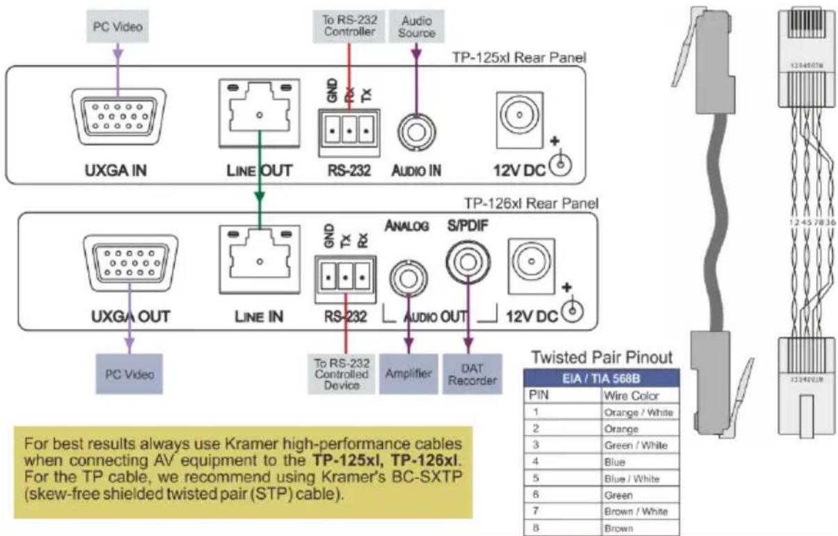
W["For best results always use Kramer high-performance cables when connecting AV equipment to the TP-125xl, TP-126xl. For the TP cable, we recommend using Kramer's BC-SXTP (skew-free shielded twisted pair (STP) cable)."]
X["Pin: 1 Orange/White, 2 Orange, 3 Green/White, 4 Blue, 5 Blue/White, 6 Green, 7 Brown/White, 8 Brown"]
Step 4: Connect the power

Connect the power adapters to the TP-125xl and TP-126xl and plug the adapters into the mains electricity.
Contents
1 Introduction 1
2 Getting Started 2
2.1 Achieving the Best Performance 2
2.2 Safety Instructions 2
2.3 Shielded Twisted Pair/Unshielded Twisted Pair 3
2.4 Recycling Kramer Products 3
3 Overview 4
4 Defining the TP-125xl/TP-126xl Line Transmitter and Receiver 5
4.1 Defining the TP-125xl UXGA/Audio/Data Line Transmitter 6
4.2 Defining the TP-126xl UXGA/Audio/Data Line Receiver 7
5 Connecting the TP-125xl and TP-126xl 8
6 Operating the TP-125xl and TP-126xl 10
6.1 Capturing the EDID 10
6.2 Adjusting the Level and Equalization on the TP-126xl 10
7 Wiring the Twisted Pair RJ-45 Connectors 11
8 Technical Specifications 12
Figures
Figure 1: TP-125xl UXGA/Audio/Data Line Transmitter Front Panel 6
Figure 2: TP-125xl UXGA/Audio/Data Line Transmitter Rear Panel 6
Figure 3: TP-126xl UXGA/Audio/Data Line Receiver Front Panel 7
Figure 4: TP-126xl UXGA/Audio/Data Line Receiver Rear Panel 7
Figure 5: Connecting the TP-125xl Transmitter and TP-126xl Receiver 8
Figure 6: TP Pinout Wiring 11
1 Introduction
Welcome to Kramer Electronics! Since 1981, Kramer Electronics has been providing a world of unique, creative, and affordable solutions to the vast range of problems that confront video, audio, presentation, and broadcasting professionals on a daily basis. In recent years, we have redesigned and upgraded most of our line, making the best even better!
Our 1,000-plus different models now appear in 11 groups that are clearly defined by function: GROUP 1: Distribution Amplifiers; GROUP 2: Switchers and Routers; GROUP 3: Control Systems; GROUP 4: Format/Standards Converters; GROUP 5: Range Extenders and Repeaters; GROUP 6: Specialty AV Products; GROUP 7: Scan Converters and Scalers; GROUP 8: Cables and Connectors; GROUP 9: Room Connectivity; GROUP 10: Accessories and Rack Adapters and GROUP 11: Sierra Video Products.
Thank you for purchasing the Kramer TOOLS ^® TP-125xl UXGA/Audio/Data Line Transmitter and/or TP-126xl UXGA/Audio/Data Line Receiver which are ideal for:
• Presentation and multimedia applications
- Long range graphics distribution for schools, hospitals, stores and security applications
2 Getting Started
We recommend that you:
- Unpack the equipment carefully and save the original box and packaging materials for possible future shipment
• Review the contents of this user manual

Go to www.kramerav.com/support/product_downloads.asp to check for up-to-date user manuals, application programs, and to check if firmware upgrades are available (where appropriate).
2.1 Achieving the Best Performance
To achieve the best performance:
- Use only good quality connection cables (we recommend Kramer high-performance, high-resolution cables) to avoid interference, deterioration in signal quality due to poor matching, and elevated noise levels (often associated with low quality cables)
• Do not secure the cables in tight bundles or roll the slack into tight coils - Avoid interference from neighboring electrical appliances that may adversely influence signal quality
- Position your Kramer TP-125xl and TP-126xl away from moisture, excessive sunlight and dust

This equipment is to be used only inside a building. It may only be connected to other equipment that is installed inside a building.
2.2 Safety Instructions

Caution: There are no operator serviceable parts inside the unit
Warning: Use only the Kramer Electronics input power wall adapter that is provided with the unit
Warning: Disconnect the power and unplug the unit from the wall before installing
2.3 Shielded Twisted Pair/Unshielded Twisted Pair
We recommend that you use Shielded Twisted Pair (STP) cable, and stress that the compliance to electromagnetic interference was tested using STP cable. There are different levels of STP cable available, and we advise you to use the best quality STP cable that you can afford. Our non-skew-free cable, Kramer BC-STP is intended for analog signals where skewing is not an issue.
In cases where there is skewing, our Unshielded Twisted Pair (UTP) skew-free cable, Kramer BC-XTP, may be advantageous, and UTP cable might also be preferable for long range applications. In any event when using UTP cable, it is advisable to ensure that the cable is installed far away from electric cables, motors and so on, which are prone to create electrical interference.
2.4 Recycling Kramer Products
The Waste Electrical and Electronic Equipment (WEEE) Directive 2002/96/EC aims to reduce the amount of WEEE sent for disposal to landfill or incineration by requiring it to be collected and recycled. To comply with the WEEE Directive, Kramer Electronics has made arrangements with the European Advanced Recycling Network (EARN) and will cover any costs of treatment, recycling and recovery of waste Kramer Electronics branded equipment on arrival at the EARN facility. For details of Kramer's recycling arrangements in your particular country go to our recycling pages at www.kramerav.com/support/recycling/.
3 Overview
The TP-125xl and TP-126xl are a high-performance, TP (Twisted Pair) transmitter and receiver pair for transmitting computer graphics video, unbalanced stereo audio, and bidirectional RS-232 data signals over extended distances using CAT 5/6 cable.
The TP-125xl encodes computer graphics video, unbalanced stereo audio and RS-232 data into a TP signal. The TP-126xl decodes the TP signal into computer graphics video, digital unbalanced stereo audio, and RS-232 data signals. The TP-125xl and TP-126xl together form an extended computer graphics/audio/data line transmission and reception system.
More specifically, the TP-125xl and TP-126xl support:
• Video resolutions up to UXGA (1920 x 1200)
• EDID (TP-125xl)
HDTV
• Level (gain) and equalization (peaking) adjustment (TP-126xl)
• Full duplex, bidirectional RS-232 transmission
- Increased level of protection against noise, spikes and interference in adverse environments
• Transmission range of up to 250m (820ft)
4 Defining the TP-125xl/TP-126xl Line Transmitter and Receiver
This section defines the:
• TP-125xl UXGA/Audio/Data Line Transmitter (see Section 4.1)
• TP-126xl UXGA/Audio/Data Line Receiver (see Section 4.2)
The TP-125xl has inputs for:
• Computer graphics video
• Unbalanced stereo audio
RS-232 data
The TP-125xl encodes the video, audio and data signals and transmits them over STP cable to a TP-126xl receiver. RS-232 data and commands flow bidirectionally, allowing status requests and control of a destination unit. The RS-232 interface makes it possible to control almost any device over a transmission range of up to 250m over STP cabling.
The TP-126xl accepts the encoded signal over STP from the TP-125xl and outputs computer graphics video, unbalanced stereo audio, digital audio and RS-232 data.
4.1 Defining the TP-125xl UXGA/Audio/Data Line Transmitter
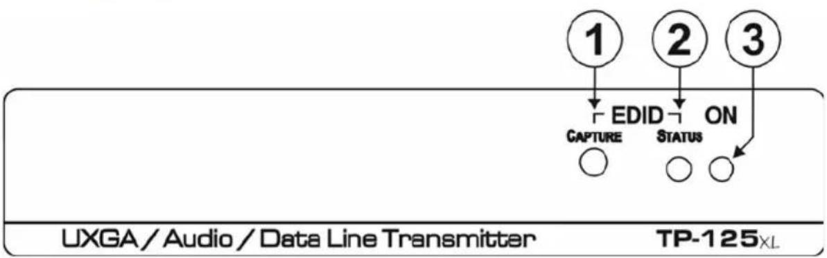
Figure 1 defines the front panel of the TP-125xl.
flowchart
graph TD
    A["1"] --> B["CAPTURE"]
    C["2"] --> D["EDID"]
    E["3"] --> F["STATUS"]
    B --> G["○"]
    D --> H["○"]
    F --> I["○"]
    G --> J["TP-125XL"]
    H --> J
    I --> J
Figure 1: TP-125xl UXGA/Audio/Data Line Transmitter Front Panel
| # | Feature | Function | |
| 1 | EDID | CAPTURE Button | Press to capture the EDID from the video display |
| 2 | STATUS LED | Indicates the following EDID status:Flashes slowly then lights solid—new EDID storedFlashes quickly then lights solid—default EDID stored | |
| 3 | ON LED | Lights green when the device is powered on | |
Figure 2 defines the rear panel of the TP-125xl.

Figure 2: TP-125xl UXGA/Audio/Data Line Transmitter Rear Panel
| # | Feature | Function |
| 4 | UXGA IN 15-pin HD Connector (F) | Connect to a computer graphics source (see Section 5) |
| 5 | LINE OUT RJ-45 Connector | Connect to the Line In RJ-45 connector on the TP-126xl (see Section 2.3) |
| 6 | RS-232 Serial Port 3-pin Terminal Block | Connect to an RS-232 device (PC or controller).Note: The RS-232 link is bidirectional |
| 7 | AUDIO IN 3.5mm Mini Jack | Connect to an unbalanced, stereo audio source (see Section 5) |
| 8 | 12V DC Power Connector | Connect to one of the supplied +12V DC power adapters. Center pin positive |
4.2 Defining the TP-126xl UXGA/Audio/Data Line Receiver
Figure 3 defines the front panel of the TP-126xl.

Figure 3: TP-126xl UXGA/Audio/Data Line Receiver Front Panel
| # | Feature | Function |
| 1 | LINK LED | Lights green when the TP link is established |
| 2 | LEVEL Trimmer | Use to adjust the output signal level (see Section 6.2) |
| 3 | EQ. Trimmer | Use to adjust the cable compensation equalization level |
| 4 | ON LED | Lights green when the device is powered on |
Figure 4 defines the rear panel of the TP-126xl.
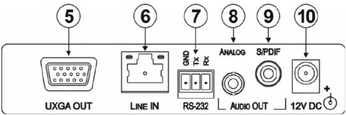
Figure 4: TP-126xl UXGA/Audio/Data Line Receiver Rear Panel
| # | Feature | Function | |
| 5 | UXGA OUT 15-pin HD Connector (F) | Connect to a computer graphics video acceptor (see Section 5) | |
| 6 | LINE IN RJ-45 Connector | Connect to the Line Out RJ-45 connector on the TP-125xl (See Section 2.3) | |
| 7 | RS-232 Serial Port 3-pin Terminal Block | Connect to the RS-232 device to be controlled.Note: The RS-232 link is bidirectional | |
| 8 | AUDIO OUT | ANALOG 3.5mm Mini Jack | Connect to an unbalanced, stereo audio acceptor (see Section 5) |
| 9 | S/PDIF RCA Connector | Connect to a digital audio acceptor | |
| 10 | 12V DC Power Connector | Connect to one of the supplied +12V DC power adapters. Center pin positive | |
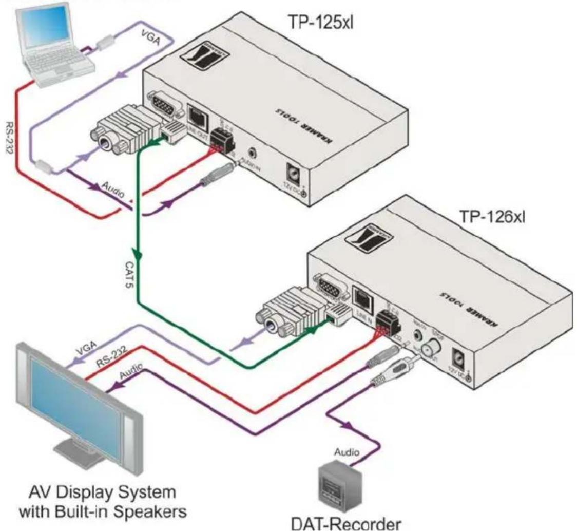
5 Connecting the TP-125xl and TP-126xl

Switch off the power to all devices before connecting them to your TP-125xl/TP-126xl. After connecting your TP-125xl/TP-126xl, connect the power to the transmitter and receiver and then switch on the power to the other devices.
Computer Graphics/Audio/RS-232 Control
flowchart
graph TD
    A["TP-125xl"] -->|VGA| B["TVDA"]
    A -->|RS23| C["TVDA"]
    A -->|Audio| D["TVDA"]
    E["TP-126xl"] -->|CATs| F["TVDA"]
    E -->|VGA| G["TVDA"]
    E -->|RS-232| H["TVDA"]
    E -->|Audio| I["TVDA"]
    J["AV Display System with Built-in Speakers"] --> K["TVDA"]
    K --> L["TVDA"]
    L --> M["TVDA"]
    M --> N["TVDA"]
    N --> O["TVDA"]
    O --> P["TVDA"]
    P --> Q["TVDA"]
    Q --> R["TVDA"]
    R --> S["TVDA"]
    S --> T["TVDA"]
    T --> U["TVDA"]
    U --> V["TVDA"]
    V --> W["TVDA"]
    W --> X["TVDA"]
    X --> Y["TVDA"]
    Y --> Z["TVDA"]
    Z --> AA["TVDA"]
    AA --> AB["TVDA"]
    AB --> AC["TVDA"]
    AC --> AD["TVDA"]
    AD --> AE["TVDA"]
    AE --> AF["TVDA"]
    AF --> AG["TVDA"]
Figure 5: Connecting the TP-125xl Transmitter and TP-126xl Receiver
To connect the TP-125xl and the TP-126xl as illustrated in Figure 5:
- On the TP-125xl, connect:
The computer graphics video source, (for example, the graphics output from a laptop) to the UXGA In 15-pin HD connector (F)
The RS-232 controller, (for example, a laptop controller with an RS-232 interface) to the RS-232 3-pin terminal block
An unbalanced, stereo audio source, (for example, the audio output from a laptop) to the Audio In 3.5mm mini jack
- On the TP-126xl, connect:
The UXGA Out 15-pin HD (F) connector to the video acceptor, (for example, an AV display system)
The RS-232 3-pin terminal block to the controlled device, (for example, an AV display system)
The Audio Out Analog 3.5mm mini jack to the unbalanced, stereo audio acceptor, (for example, an AV display system with speakers)
The Audio Out S/PDIF RCA connector to the digital audio acceptor, (for example, a DAT recorder)
- Using STP cabling, connect the TP-125xl Line Out RJ-45 connector to the TP-126xl Line In RJ-45 connector (see Section 2.3).
- Connect the power adapters to the power sockets on the TP-125xl and TP-126xl, and connect the adapters to the mains electricity (not shown in Figure 5).
- If necessary, adjust the level and equalization for an optimum picture (see Section 6.2).
6 Operating the TP-125xl and TP-126xl
6.1 Capturing the EDID
The TP-125xl is programmed with a default EDID. To replace the default EDID you can replace it with the EDID from a display device.
To capture a new EDID:
- With the display device connected to the TP-125xl, press the EDID Capture button on the front panel of the TP-125xl. If the EDID is successfully captured the Status LED flashes slowly for a few seconds and then lights solid. If the EDID is not successfully captured the Status LED flashes quickly for a few seconds then lights solid when the default EDID is loaded.
6.2 Adjusting the Level and Equalization on the TP-126xl
You can manually adjust the signal level and equalization using the trimmers on the front of the TP-126xl to achieve an optimum picture.
To adjust the level and equalization on the TP-126xl:
- Use a small screwdriver to slowly turn the Level trimmer clockwise to increase or anticlockwise to reduce the signal level of the TP-126xl.
- Use a small screwdriver to slowly turn the EQ trimmer clockwise or anticlockwise until you achieve an optimum picture.
7 Wiring the Twisted Pair RJ-45 Connectors
When using STP cable, connect/solder the cable shield to the RJ-45 connector shield. Figure 6 defines the TP pinout using a straight pin-to-pin cable with RJ-45 connectors.
EIA /TIA 568B
| PIN | Wire Color |
| 1 | Orange / White |
| 2 | Orange |
| 3 | Green / White |
| 4 | Blue |
| 5 | Blue / White |
| 6 | Green |
| 7 | Brown / White |
| 8 | Brown |
| Pair 1 | 4 and 5 |
| Pair 2 | 1 and 2 |
| Pair 3 | 3 and 6 |
Figure 6: TP Pinout Wiring


Warning:
Using a TP cable that is incorrectly wired will cause permanent damage to the device
8 Technical Specifications
| TP-125xl | TP-126xl | ||
| INPUTS: | 1 UXGA on a 15-pin HD connector (F)1 Unbalanced stereo audio on a 3.5mm mini jack1 Bidirectional RS-232 serial port on a 3-pin terminal block | 1 TP on an RJ-45 connector | |
| OUTPUTS: | 1 TP on an RJ-45 connector | 1 UXGA on a 15-pin HD connector (F)1 Digital audio on an RCA connector1 Unbalanced stereo audio on a 3.5mm mini jack1 Bidirectional RS-232 serial port on a 3-pin terminal block | |
| VIDEO RESOLUTION: | Up to WUXGA, 1080p | ||
| MAX. OUTPUT LEVEL: Video: | 1.1V | Audio: 2.2V | |
| AUDIO: | BANDWIDTH: | Audio: 20Hz-20kHz @-3dB | |
| S/N RATIO: Audio: 84dB unweighted | |||
| COUPLING: | AC | ||
| TND+N: | Audio: 0.02% unweighted | ||
| TOTAL GAIN: | Analog/analog: 0dBAnalog/SPDIF: -12dBFS | ||
| RS-232: | BAUD RATE: | 9600, 19200bps | |
| MODE: | Full-duplex | ||
| POWER CONSUMPTION: | 12V DC 206mA | 12V DC 235mA | |
| TRANSMISSION DISTANCE: | Up to 250m (820ft) | ||
| OPERATING TEMPERATURE: | 0° to +40°C (32° to 104°F) | ||
| STORAGE TEMPERATURE: | -40° to +70°C (-40° to 158°F) | ||
| HUMIDITY: | 10% to 90%, RHL non-condensing | ||
| DIMENSIONS: | 12.1cm x 7.18cm x 2.48cm (4.76" x 2.83" x 0.98"), W, D, H | ||
| WEIGHT: | 0.2kg (0.44lbs.) approx. each | ||
| ACCESSORIES: | Power supply | ||
| OPTIONS: | RK-3T 19" rack adapter | ||
LIMITED WARRANTY
The warranty obligations of Kramer Electronics for this product are limited to the terms set forth below:
What is Covered
This limited warranty covers defects in materials and workmanship in this product.
What is Not Covered
This limited warranty does not cover any damage, deterioration or malfunction resulting from any alteration, modification, improper or unreasonable use or maintenance, misuse, abuse, accident, neglect, exposure to excess moisture, fire, improper packing and shipping (such claims must be presented to the carrier), lightning, power surges, or other acts of nature. This limited warranty does not cover any damage, deterioration or malfunction resulting from the installation or removal of this product from any installation, any unauthorized tampering with this product, any repairs attempted by anyone unauthorized by Krame Electronics to make such repairs, or any other cause which does not relate directly to a defect in materials and/or workmanship of this product. This limited warranty does not cover cartons, equipment enclosures, cables or accessories used in conjunction with this product.
Without limiting any other exclusion herein, Kramer Electronics does not warrant that the product covered hereby, including, without limitation, the technology and/or integrated circuit(s) included in the product, will not become obsolete or that such items are or will remain compatible with any other product or technology with which the product may be used.
How Long Does this Coverage Last
Seven years as of this printing; please check our Web site for the most current and accurate warranty information.
Who is Covered
Only the original purchaser of this product is covered under this limited warranty. This limited warranty is not transferable to subsequent purchasers or owners of this product.
What Kramer Electronics will do
Kramer Electronics will, at its sole option, provide one of the following three remedies to whatever extent it shall deem necessary to satisfy a proper claim under this limited warranty:
- Elect to repair or facilitate the repair of any defective parts within a reasonable period of time, free of any charge for the necessary parts and labor to complete the repair and restore this product to its proper operating condition. Kramer Electronics will also pay the shipping costs necessary to return this product once the repair is complete.
- Replace this product with a direct replacement or with a similar product deemed by Kramer Electronics to perform substantially the same function as the original product.
- Issue a refund of the original purchase price less depreciation to be determined based on the age of the product at the time remedy is sought under this limited warranty.
What Kramer Electronics will not do Under This Limited Warranty
If this product is returned to Kramer Electronics or the authorized dealer from which it was purchased or any other party authorized to repair Kramer Electronics products, this product must be insured during shipment, with the insurance and shipping charges prepaid by you. If this product is returned uninsured, you assume all risks of loss or damage during shipment. Kramer Electronics will not be responsible for any costs related to the removal or re-installation of this product from or into any installation. Kramer Electronics will not be responsible for any costs related to any setting up this product, any adjustment of user controls or any programming required for a specific installation of this product.
How to Obtain a Remedy under this Limited Warranty
To obtain a remedy under this limited warranty, you must contact either the authorized Kramer Electronics reseller from whom you purchased this product or the Kramer Electronics office nearest you. For a list of authorized Kramer Electronics resellers and/or Kramer Electronics authorized service providers, please visit our web site at www.kramerelectronics.com or contact the Kramer Electronics office nearest you.
In order to pursue any remedy under this limited warranty, you must possess an original, dated receipt as proof of purchase from an authorized Kramer Electronics reseller. If this product is returned under this limited warranty, a return authorization number, obtained from Kramer Electronics, will be required. You may also be directed to an authorized reseller or a person authorized by Kramer Electronics to repair the product.
If it is decided that this product should be returned directly to Kramer Electronics, this product should be properly packed, preferably in the original carton, for shipping. Cartons not bearing a return authorization number will be refused.
Limitation on Liability
THE MAXIMUM LIABILITY OF KRAMER ELECTRONICS UNDER THIS LIMITED WARRANTY SHALL NOT EXCEED THE ACTUAL PURCHASE PRICE PAID FOR THE PRODUCT. TO THE MAXIMUM EXTENT PERMITTED BY LAW, KRAMER ELECTRONICS IS NOT RESPONSIBLE FOR DIRECT, SPECIAL, INCIDENTAL OR CONSEQUENTIAL DAMAGES RESULTING FROM ANY BREACH OF WARRANTY OR CONDITION, OR UNDER ANY OTHER LEGAL THEORY. Some countries, districts or states do not allow the exclusion or limitation of relief, special, incidental, consequential or indirect damages, or the limitation of liability to specified amounts, so the above limitations or exclusions may not apply to you.
Exclusive Remedy
TO THE MAXIMUM EXTENT PERMITTED BY LAW, THIS LIMITED WARRANTY AND THE REMEDIES SET FORTH ABOVE ARE EXCLUSIVE AND IN LIEU OF ALL OTHER WARRANTIES, REMEDIES AND CONDITIONS, WHETHER ORAL OR WRITTEN, EXPRESS OR IMPLIED. TO THE MAXIMUM EXTENT PERMITTED BY LAW, KRAMER ELECTRONICS SPECIFICALLY DISCLAIMS ANY AND ALL IMPLIED WARRANTIES, INCLUDING, WITHOUT LIMITATION, WARRANTIES OF MERCHANTABILITY AND FITNESS FOR A PARTICULAR PURPOSE. IF KRAMER ELECTRONICS CANNOT LAWFULLY DISCLAIM OR EXCLUDE IMPLIED WARRANTIES UNDER APPLICABLE LAW, THEN ALL IMPLIED WARRANTIES COVERING THIS PRODUCT, INCLUDING WARRANTIES OF MERCHANTABILITY AND FITNESS FOR A PARTICULAR PURPOSE, SHALL APPLY TO THIS PRODUCT AS PROVIDED UNDER APPLICABLE LAW.
IF ANY PRODUCT TO WHICH THIS LIMITED WARRANTY APPLIES IS A "CONSUMER PRODUCT" UNDER THE MAGNUSON-MOSS WARRANTY ACT (15 U.S.C.A. §2301, ET SEQ.) OR OTHER APPLICABLE LAW, THE FOREGOING DISCLAIMER OF IMPLIED WARRANTIES SHALL NOT APPLY TO YOU, AND ALL IMPLIED WARRANTIES ON THIS PRODUCT, INCLUDING WARRANTIES OF MERCHANTABILITY AND FITNESS FOR THE PARTICULAR PURPOSE, SHALL APPLY AS PROVIDED UNDER APPLICABLE LAW.
Other Conditions
This limited warranty gives you specific legal rights, and you may have other rights which vary from country to country or state to state.
This limited warranty is void if (i) the label bearing the serial number of this product has been removed or defaced, (ii) the product is not distributed by Kramer Electronics or (iii) this product is not purchased from an authorized Kramer Electronics reseller. If you are unsure whether a reseller is an authorized Kramer Electronics reseller, please visit our Web site at www.kramerelectronics.com or contact a Kramer Electronics office from the list at the end of this document.
Your rights under this limited warranty are not diminished if you do not complete and return the product registration form or complete and submit the online product registration form. Kramer Electronics thanks you for purchasing a Kramer Electronics product. We hope it will give you years of satisfaction.

For the latest information on our products and a list of Kramer distributors, visit our Web site where updates to this user manual may be found.
We welcome your questions, comments, and feedback.
Web site: www.kramerav.com
E-mail: info@kramerel.com


SAFETY WARNING
Disconnect the unit from the power supply before opening and servicing

P/N: 2900-300206
Rev: 4


- Step 1: Check what's in the box
- Step 2: Install the TP-125xl or TP-126xl
- Step 3: Connect the inputs and outputs
- Step 4: Connect the power
- Contents
- Introduction 1
- Getting Started 2
- Overview 4
- Figures
- Introduction
- Getting Started
- Achieving the Best Performance
- Safety Instructions
- Shielded Twisted Pair/Unshielded Twisted Pair
- Recycling Kramer Products
- Overview
- Defining the TP-125xl/TP-126xl Line Transmitter and Receiver
- Defining the TP-125xl UXGA/Audio/Data Line Transmitter
- Defining the TP-126xl UXGA/Audio/Data Line Receiver
- Connecting the TP-125xl and TP-126xl
- To connect the TP-125xl and the TP-126xl as illustrated in Figure 5:
- Operating the TP-125xl and TP-126xl
- Capturing the EDID
- To capture a new EDID:
- Adjusting the Level and Equalization on the TP-126xl
- To adjust the level and equalization on the TP-126xl:
- Wiring the Twisted Pair RJ-45 Connectors
- Warning:
- Technical Specifications
- LIMITED WARRANTY
- What is Covered
- What is Not Covered
- How Long Does this Coverage Last
- Who is Covered
- What Kramer Electronics will do
- What Kramer Electronics will not do Under This Limited Warranty
- How to Obtain a Remedy under this Limited Warranty
- Limitation on Liability
- Exclusive Remedy
- Other Conditions
- SAFETY WARNING
Brand : Kramer
Model : TP-125xl
Category : AV Transmitter