
F3X - Tracking Chauvet - Free user manual and instructions
Find the device manual for free F3X Chauvet in PDF.


| Product Type | Indoor LED Video Panel |
| Model | F3X |
| Pixel Pitch | 3.9 mm |
| Pixels per Panel | 128 x 256 (32,768 total) |
| Refresh Rate | 3,840 Hz (S-PWM) |
| Viewing Angle (H/V) | 140° / 110° |
| Calibrated Illuminance | 1,000 NITS |
| Maximum Illuminance | 1,200 NITS |
| Light Source | Tri-color RGB SMD 2121 LED |
| Dimensions | 19 x 39 x 2.5 in (500 x 1000 x 64 mm) |
| Weight | 30 lb (13.6 kg) |
| Housing Material | Magnesium die-cast |
| Operating Temperature | -4 °F to 131 °F (-20 °C to 55 °C) |
| AC Voltage Range | 100–240 VAC, 50/60 Hz (auto-ranging) |
| Power Consumption | 305 W typical |
| Power Linking | Up to 5 units @120V, 10 @208V, 11 @230V |
| Control Protocol | Novastar |
| Signal Connection | Seetronic Etherkon® IP65 |
| Power Connection | Seetronic Powerkon® IP65 |
| Included Accessories | 4 panels, road case, power cords, signal cords, 5 spare LED masks, Quick Reference Guide |
| Special Features | S-PWM, magnetic LED modules, front/rear serviceability, calibration recall |
| Cleaning Instructions | Use 99% isopropyl alcohol with gentle pressure; avoid damaging anti-reflective coating |
Frequently Asked Questions - F3X Chauvet
User questions about F3X Chauvet
0 question about this device. Answer the ones you know or ask your own.
Ask a new question about this device
Download the instructions for your Tracking in PDF format for free! Find your manual F3X - Chauvet and take your electronic device back in hand. On this page are published all the documents necessary for the use of your device. F3X by Chauvet.
USER MANUAL F3X Chauvet
Edition Notes
The F3X User Manual includes a description, safety precautions, installation, programming, operation and maintenance instructions for the F3X as of the release date of this edition.
Trademarks
CHAUVET, the Chauvet logo, and F3X are registered trademarks or trademarks of Chauvet & Sons, LLC (d/b/a Chauvet and Chauvet Lighting) in the United States and other countries. Other company and product names and logos referred to herein may be trademarks of their respective companies.
Copyright Notice
The works of authorship contained in this manual, including, but not limited to, all design, text and images are owned by Chauvet.
© Copyright 2023 Chauvet & Sons, LLC. All rights reserved.
Electronically published by Chauvet in the United States of America.
Manual Use
Chauvet authorizes its customers to download and print this manual for professional information purposes only. Chauvet expressly prohibits the usage, copy, storage, distribution, modification, or printing of this manual or its content for any other purpose without written consent from Chauvet.
Document Printing
For best results, print this document in color, on letter size paper (8.5 x 11 in), double-sided. If using A4 paper (210 x 297 mm), configure the printer to scale the content accordingly.
Intended Audience
Any person installing, operating, and/or maintaining this product should completely read through the guide that shipped with the product, as well as this manual, before installing, operating, or maintaining this product.
Disclaimer
Chauvet believes that the information contained in this manual is accurate in all respects. However, Chauvet assumes no responsibility and specifically disclaims any and all liability to any party for any loss, damage or disruption caused by any errors or omissions in this document, whether such errors or omissions result from negligence, accident or any other cause. Chauvet reserves the right to revise the content of this document without any obligation to notify any person or company of such revision, however, Chauvet has no obligation to make, and does not commit to make, any such revisions. Download the latest version from www.chauvetprofessional.com.
Document Revision
This F3X User Manual is the 2nd edition of this document. Go to www.chauvetprofessional.com for the latest version.
TABLE OF CONTENTS
1. Before You Begin .... 1
What Is Included.... 1
Claims.... 1
Text Conventions.... 1
Symbols.... 1
Safety Notes 2
Personal Safety 2
Mounting and Rigging.... 2
Power and Wiring 2
Operation 2
Expected LED Lifespan 2
2. Introduction ...... 3
Product Description 3
Features.... 3
Required Accessories.... 3
Optional Accessories 3
Available Signal and Power Cables 3
Product Overview 4
Pixels per Panel.... 5
Scrambled Pulse-Width Modulation 5
Product Dimensions 6
3. Setup 7
AC Power 7
AC Plug.... 7
Power Linking 7
4. Mounting 8
Orientation 8
Mounting Points 8
DRB-F50CM Dual Function Rig Bar Dimensions 9
DRB-F100CM Dual Function Rig Bar Dimensions 9
Mounting with Dual Function Rig Bar (Hanging) 10
Truss Installation.... 11
Mounting with Dual Function Rig Bar (Stacking).... 12
Removing the Feet 12
Flat Wall Installation 13
Mounting Points on a Flat Wall 13
Mounting with Steel Struts 13
Spacers (Flat Wall Installation).... 14
5. Joining Each F3X (Creating a Modular Design) 15
Vertically Joining the Panels.... 15
Vertical Panel Connection 16
Horizontally Joining the Panels 17
Horizontal Panel Connection 17
6. Connecting (Cabling) Each F3X.... 18
Testing Signal and Power Connections.... 18
Using the F3X Test Button 18
Connecting Power and Signal Cables 19
Connecting the Signal Between Joined Panels 19
Custom Resolutions.... 19
Signal Chain Rectangles 20
Connecting the Power Between Joined Panels 21
7. LED Module Care and Replacement.... 22
F3X Modules 22
LED Lot Numbers 22
A and B Modules 22
Calibration Recall.... 22
F3X LED Module Removal 23
Removing a Module from the Rear.... 23
Removing and Replacing the LED Masks 24
8. F3X Serviceability.... 25
9. Typical F3X Installation (Hanging)...... 27
10. Operation 28
Additional Hardware and Software 28
About NovaLCT and SmartLCT 28
Description.... 28
Receiver Card Configuration Files.... 28
Updating RCFGX Files (NovaLCT).... 29
Rotating the Video Panel Orientation (NovaLCT) 30
Updating RCFGX Files (SmartLCT) 31
11. Technical Information 32
F3X Maintenance 32
12. Technical Specifications .... 33
Contact Us 34
Warranty & Returns 34
1. Before You Begin
What Is Included
- 4 F3X products
- 1 Road case
• 1 Seetronic Powerkon IP65 power cord
• 4 Seetronic ® Powerkon ® IP65 power linking cords
• 4 Seetronic Etherkon IP65 signal linking cords
- 5 spare LED masks
- Quick Reference Guide
Claims
Carefully unpack the product immediately and check the container to make sure all the parts are in the package and are in good condition.
If the box or the contents (the product and included accessories) appear damaged from shipping, or show signs of mishandling, notify the carrier immediately, not Chauvet. Failure to report damage to the carrier immediately may invalidate a claim. In addition, keep the box and contents for inspection.
For other issues, such as missing components or parts, damage not related to shipping, or concealed damage, file a claim with Chauvet within 7 days of delivery.
Text Conventions
| Convention Meaning | |
| 1–512 A range of values | |
| 50/60 A set of values of which only one can be chosen | |
| Settings A menu option not to be modified | |
| Menu > Settings | A sequence of menu options to be followed |
| A key to be pressed on the product's control panel | |
Symbols
| Symbol Meaning | |
 | Critical installation, configuration, or operation information. Not following these instructions may make the product not work, cause damage to the product, or cause harm to the operator. |
 | Important installation or configuration information. The product may not function correctly if this information is not used. |
 | Useful information. |
 | Pinch point warning. |
Safety Notes
Read all the following safety notes before working with this product. These notes contain important information about the installation, usage, and maintenance of this product.

This product contains no user-serviceable parts. Any reference to servicing in this User Manual will only apply to properly trained, certified technicians. Do not open the housing or attempt any repairs.

All applicable local codes and regulations apply to proper installation of this product.
Personal Safety
- Always disconnect the product from the power source before cleaning.
- Always connect the product to a grounded circuit to avoid the risk of electrocution.
- Do not touch the product's housing when operating because it may be very hot.
Mounting and Rigging
- WARNING: This product should only be used by competent and qualified persons.
- DO NOT operate this product outdoors or in any location where dust, excessive heat, water, or humidity may affect it. (IP31)
- CAUTION: When transferring product from extreme temperature environments, (e.g. cold truck to warm humid ballroom) condensation may form on the internal electronics of the product. To avoid causing a failure, allow product to fully acclimate to the surrounding environment before connecting it to power.
- Mount this product in a location with adequate ventilation, at least 20 in (50 cm) from adjacent surfaces.
- Make sure there are no flammable materials close to this product while it is operating.
- Never carry the product by the power cord or any moving part.
Power and Wiring
- Make sure the power cord is not crimped or damaged.
- Always connect this product to the proper voltage in accordance with the specifications in this manual or on the product's specification label.
• To eliminate unnecessary wear and improve its lifespan, during periods of non-use completely disconnect the product from power via breaker or by unplugging it. - Never connect this product to a dimmer pack or rheostat.
- Never disconnect this product by pulling or tugging on the power cable.
Operation
- Do not operate this product if there is damage on the housing, lenses, or cables. Have the damaged parts replaced by an authorized technician at once.
- Do not cover the ventilation slots when operating to avoid internal overheating.
- Operating Temperature: -4 °F to 131 °F (-20 °C to 55 °C)
• In the event of a serious operation problem, stop using this product immediately!

If this Chauvet product requires service, contact Chauvet Technical Support.
Expected LED Lifespan
Over time, use and heat will gradually reduce LED brightness. Clustered LEDs produce more heat than single LEDs, contributing to shorter lifespans if always used at full intensity. The average LED lifespan is 40,000 to 50,000 hours. To extend LED lifespan, maintain proper ventilation around the product, and limit the overall intensity.
2. Introduction
Product Description
The F3X is a 3.9mm, high resolution, indoor rated video panel in a convenient 1000mm tall by 500mm wide form factor. Users can easily configure and drive content with the VIP Drive 10-5 Nova or the VIP Drive 83R Nova, powered by the Novastar control protocol. The F3X also features high quality back body LEDS producing at 14-bit grayscale and high performance digital LED drivers that deliver a clear, vibrant image.
Features
- 3.9 mm pitch, high-resolution, indoor rated video panel in convenient 1000 mm (tall) by 500 mm (wide) form factor.
- Easily configure and drive content with the VIP Drive 10-5 Nova or the VIP Drive 83R Nova, powered by the Novastar control protocol
- High quality black body LEDs accurately reproduce video at 14-bit grayscale, operating on the A5s receiver card from Novastar (18-bit available)
• High performance digital LED drivers deliver 3840 Hz refresh rate and a clear, vibrant image - Uses specialized LED dimming control via S-PWM (Scrambled Pulse-Width Modulation ____, which enhances on-camera performance.
- Intelligent, high speed magnetic LED modules with dedicated memory stores factory calibration, ensuring optimal image quality, color uniformity, and simplifies maintenance by making service fast and easy
- 1,000 x 500 x 82.5 mm, 28.6 lb (13 kg) magnesium die-cast housing (500 x 500 mm available) makes this product among the lightest and slimmest in its class without compromising strength, capable of hanging up to 22 panels vertically safely
- Specialized frame design allows for overhead hanging, ground stacking, and wall mounting maximizing installation flexibility and aftermarket front and rear service; simply push out modules from the rear using the handles or use the optional service tool from the front.
- Front LED surface protective design features prevent damage when handling: specialized LED board design to improve impact resistance up to 3x that of other panels, and resilient led mask design to optimize image viewing angle and uniformity without exposing the LEDs to front or side impacts
• Strong, magnetic assisted hanging makes setting up the panels fast and easy with a minimal crew - Optimized heat dissipation ensures an even color across the F3X
- Dual power supplies increase the stability of the system
- Ground support system, and concave curving hardware available
- Easily replace the LED masks without tools so the display remains flat even after mishandling
- Ground support system and concave curving hardware available
Required Accessories
- Required Software: NovaLCT
- Controller (required): VIP Drive 10-5 Nova, VIP Drive 83R Nova
- Compatible Mounting Options: F-series™ Dual Function Rig Bar (0.5 m, 1 m) (truss mounting) M12 Bolt/Clamp (rear or surface mounting), GROUNDSUPPORT2KIT (floor mounting)
Optional Accessories
• ArKaos Media Master Express + KN software
- Neutrik powerCON cables
- Neutrik etherCON cables
- DRB-100CM
- DRB-50CM
• D R B - C u r v e X 2
• GROUNDSUPPORT2KIT
• VIDCURVEKIT
Available Signal and Power Cables
Signal cables (Neutrik ® etherCON ® CAT6 Signal Extensions)
- ETHERCONEXT,
• 1 8 I N
5FT
• 1 0 F T
• 2 5 F T
• 5 0 F T
Power cables (Seetronic® Powerkon Power Extensions)
- IP65 Rated Seetronic® Powerkon Extension,
• 5 f t
• 10 ft
• 25 ft
Product Overview

Pixels per Panel

Each pixel is 1 tri-color LED. The following table provides the pixels per panel in each F3X. For detailed specifications, refer to the Technical Specifications table at the end of this User Manual.
| Parameter F3X |
| Pixels per Panel 128 x 256 |
| Total Pixels per Panel 32,768 |
| Pixels per LED Module 64 x 128 |
| Total Pixels per LED Module 8,192 |
| LED Module Dimensions 250 x 500 mm |

To calculate the number of panels, horizontally and vertically, supported by a single VIP Drive 10-5 Nova or VIP Drive 83R Nova, use:
• The number of pixels per panel.
- The screen resolution desired for the video wall display.
The VIP Drive 10-5 Nova or VIP Drive 83R Nova is required to operate an F3X video wall system. Diagrams of how the F3X panels and the VIP Drive connect follow later in this manual. For detailed information about the VIP Drive and panel calculation examples, refer to the User Manual for the VIP Drive 10-5 Nova or VIP Drive 83R Nova.
Scrambled Pulse-Width Modulation
This product features Scrambled-PWM (S-PWM) technology, which de-synchronizes the pulse widths of each color of the multi-color LEDs. This ensures that there is always some LED output, reducing flicker, and maintaining the same grayscale performance.
Product Dimensions

3. Setup
AC Power
The F3X has an auto-ranging power supply and can work with an input voltage range of 100 to 240 VAC, 50/60 Hz. To determine the product's power requirements (circuit breaker, power outlet, and wiring), use the current value listed on the label affixed to the product's back panel, or refer to the product's specifications chart. The listed current rating indicates the product's average current draw under normal conditions.

• Always connect the product to a protected circuit (a circuit breaker or fuse). Make sure the product has an appropriate electrical ground to avoid the risk of electrocution or fire.
• To eliminate unnecessary wear and improve its lifespan, during periods of non-use completely disconnect the product from power via breaker or by unplugging it.

Never connect the product to a rheostat (variable resistor) or dimmer circuit, even if the rheostat or dimmer channel serves only as a 0 to 100% switch.
AC Plug
The F3X comes with a power input cord terminated with a Seetronic Powerkon A connector on one end and an Edison plug on the other end (U.S. market). If the power input cord that came with the product has no plug, or if it is necessary to change the plug, use the table below to wire the new plug.
| Connection | Wire (U.S.) | Wire (Europe) | Screw Color |
| AC Live Black Brown Yellow or Brass | |||
| AC Neutral White Blue Silver | |||
| AC Ground Green/Yellow Green/Yellow | Green |
Power Linking

All F3X panels support power linking. Refer to the following table for specifications.
| Voltage | F3X Products |
| @ 120 V, 60 Hz | 5 |
| @ 208 V, 60 Hz | 10 |
| @ 230 V, 50 Hz | 11 |

Please refer to all applicable local codes and regulations for the proper installation of this product.
4. Mounting
Orientation
Each F3X is constructed of die-cast magnesium. This ensures each panel is stable and easy to install. Each panel also has convenient built-in handles located on the top and bottom of the backside of the panel along with two alignment conicals on the top and 4 alignment bolts (feet) on the bottom. This combination enables the user to easily pick up and securely hold each panel while mounting and working with the panels.
The F3X can be assembled to provide any number of modular designs. The panels on the top can be securely hung from a truss or other stable surface. Always hang in a safe position with adequate space for ventilation, configuration, and maintenance. Chauvet recommends following the general guidelines below.
- When selecting an installation location, consider ease of access for operation and routine maintenance.
• Make sure to hang away from any flammable material, as indicated in the Safety Notes section. - Never mount in places where rain, extreme temperature changes, or restricted ventilation may affect it.
- Make sure that the structure and attachment points can support the weight before hanging the panels.
- Make sure that all load-bearing hardware used can support the weight.
• See the Technical Specifications for the weight requirement of each F3X.
Mounting Points
- Threaded Mounting Holes Size M12 (x6)
- Male Speego Connection
- Female Speego Connection
- Feet (Alignment Bolts) (x4)
- Handles

DRB-F50CM Dual Function Rig Bar Dimensions

DRB-F100CM Dual Function Rig Bar Dimensions
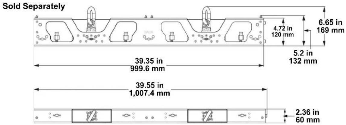
Mounting with Dual Function Rig Bar (Hanging)

- Loosen the spring knobs on the male Speego connections of each Rig Bar to be used.
- Insert alignment conicals into the alignment holes and allow magnets to connect.
- Insert the Rig Bar Speego locking bars into the female Speego connections on the F3X.
- Twist the spring knob on the Rig Bar Speego until it locks into place.

When mounting a video panel assembly together, mount the entire top row of panels using only the spring knobs before moving on to step 5.
- Twist the tightening knobs clockwise until the F3X products are secure to the Rig Bars and aligned correctly to each other.
- Install the side latches of the panels to each other (Horizontal Panel Connection) only after ensuring the alignment is correct.
- To detach the Rig Bar from the F3X, reverse the previous steps. Tilt the panels away from each other to safely release the magnetic attachments.

The alignment magnets on the F3X and Dual Function Rig Bar are designed to temporarily hold the weight of the panel to allow the user to properly align and tighten the panel into place.

Warning! The magnetic attachments are not load-bearing, and are intended for alignment assistance only. Do not release panel until the hanging hardware has been fully secured.
Truss Installation
Attach to Truss Using Dual Function Rig Bar


The M12 and M10 mounting points are not intended for hanging or suspending from a truss or other overhead structure.
In order to suspend/hang the panels from a truss or other overhead structure, use the Dual Series Rig Bars (DRB-F50CM or -F100CM, sold separately).
All applicable local codes and regulations apply to proper installation of this product.
WARNING: The alignment magnets on the Dual Function Rig Bars are not designed for load bearing! All Rig Bars in a panel assembly must be mounted individually to the mounting point! Adjacent Rig Bars will NOT support the attached weight!
WARNING: This product should only be used by competent and qualified persons.
Mounting with Dual Function Rig Bar (Stacking)

- Insert alignment conicals into the alignment holes and allow magnets to connect.
- Close the latches of the male speego connections on the F-series panel.
- To detach the Rig Bar from the F-Series panel, reverse the previous steps.

Warning! The magnetic attachments are not load-bearing, and are intended for alignment assistance only. Do not release panel until the hanging hardware has been fully secured.
Removing the Feet
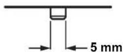
To remove the feet (alignment bolts) from the F3X, twist them counter-clockwise with a 5 mm wrench until they come loose.

Back View Side View

Removing the feet may result in damage not covered by the warranty.
Flat Wall Installation
Refer to the following diagrams for flat wall installation.
Mounting Points on a Flat Wall


The 4 rear and front mounting holes are intended for flush mount installation to a flat surface against the video panels. 1 mounting point for every junction, including outside edges and corners, must be used in order to maintain structural integrity. The mounting points are not intended for hanging or suspending from a truss or other overhead structure.
The 2 rear mounting holes in the middle of the product are intended for use with the Ground Support 2 Kit from Chauvet.
Mounting with Steel Struts
Chauvet recommends using a VERTICAL steel strut for each column of panels, plus 1, as in the following diagrams:
4 columns + 1 = 5 steel struts


Spacers greater than 5 mm thick must be used at each mounting point, between the panels and the struts.
The illustrations above are examples only. Please refer to all applicable local codes and regulations for the proper installation of the product.
Spacers (Flat Wall Installation)
When mounting to a flat wall, spacers greater than 5 mm thick must be used at each mounting point, between the panels and the struts, as in the diagram below.

5. Joining Each F3X (Creating a Modular Design)
Vertically Joining the Panels
Each F3X can be easily joined vertically to a truss using an optional rig bar and the 2 female Speego connections located at the top corners of each panel. Use the male Speego connections at the bottom of each panel to connect additional panels. These connectors stay recessed when not being used.
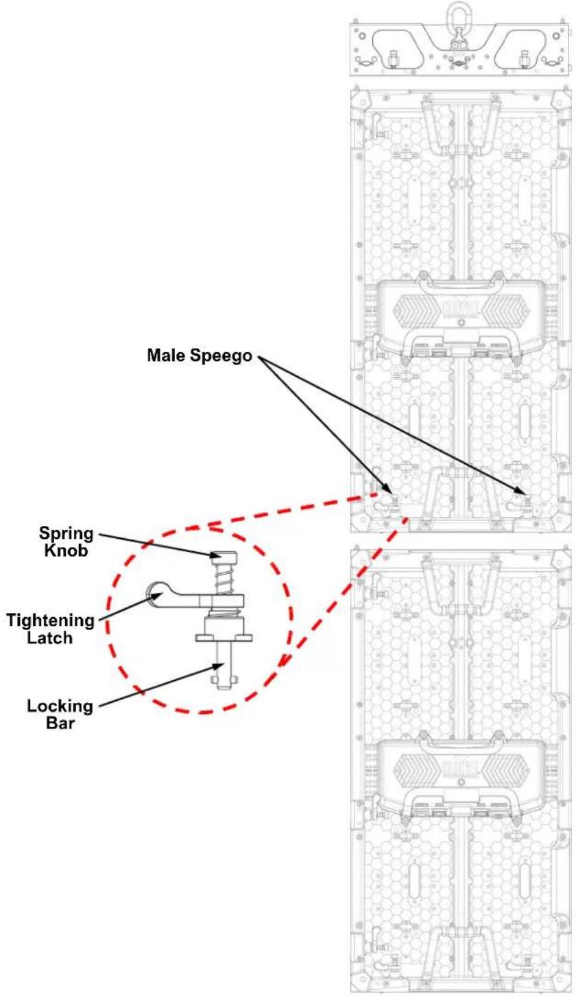
Vertical Panel Connection
Use the following instructions to join panels vertically:
- Line up the alignment conicals at the top of each panel, and the alignment magnets at the top and bottom of each panel.
- Push male Speego connections into female Speego connections.
- Turn the spring knobs clockwise until secure.
- Turn the tightening latches counter-clockwise until secure.

Due to tolerances in the materials, as well as wear and tear of the latches, some tightening latches may not line up when tightened. This is normal.


Warning! The magnetic attachments are not load-bearing, and are intended for alignment assistance only. Do not release panel until the hanging hardware has been fully secured.
Horizontally Joining the Panels
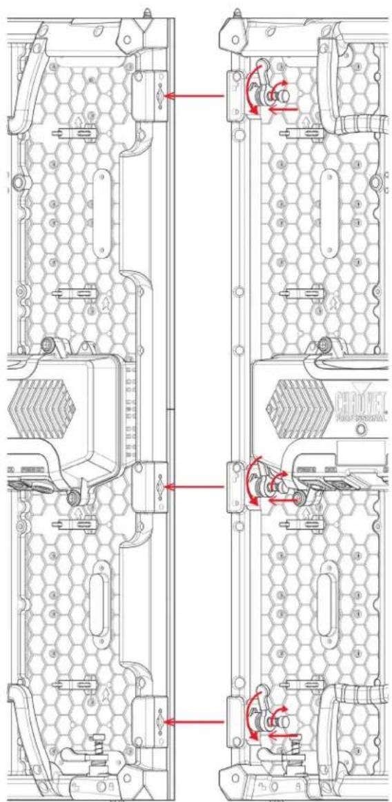
Each F3X can be easily joined horizontally using the Speego connections on the inside, upper and lower left sides of each panel.
Horizontal Panel Connection
Use the following instructions to join panels horizontally:
- Align each of the panels' male Speego connections with the corresponding female connections on the panels being added.
- Push male Speego connections into female Speego connections.
- Turn the spring knobs clockwise until secure.
- Turn the tightening latches counter-clockwise until secure.

Due to tolerances in the materials, as well as wear and tear of the latches, some tightening latches may not line up when tightened. This is normal.
6. Connecting (Cabling) Each F3X
Testing Signal and Power Connections
Each F3X has 2 power sockets and 2 signal ports.
- The Power and Signal connections are located on the underside of the service module of each panel.
• The Signal ports may be used interchangeably.
• Each F3X has LED indicator lights on the test button in the center of the panel.
• Each panel indicates a successful power connection when the Power indicator light remains red.
• Each panel indicates the presence of a signal when the Signal LED indicator light blinks green quickly. When the LED blinks green slowly, there is no signal.
Rear Panel Views Underside of Service Access Views


Using the F3X Test Button
Each F3X has a Test button, used to ensure all LEDs are functional. Use the Test button on each panel to perform a self-test. If self-testing, the user must perform the test individually for each F3X. It is not necessary to connect to a signal or use software.

When using the Test button, make sure the F3X is NOT connected to the VIP Drive 10-5 Nova or VIP Drive 83R Nova.
To use the Test button, the user must connect the power, but do not connect the signal cables. Press the Test button to toggle through various LED light display configurations.
Connecting Power and Signal Cables
The following sections provide information and diagrams on connecting signal and power between panels. Refer to the Introduction or Operation sections in this User Manual for available cables and item numbers.
Connecting the Signal Between Joined Panels
Signal cable panel connections can use several different configurations. The basic configuration to connect the signal from one panel to the next is as follows:
- The source signal is connected to the first panel.
- A signal cable is then connected from the first panel.
- The connections continue to daisy-chain until all panels are connected.
- The route of the cables used to make the signal connections can vary.
The following diagram is a recommended suggestion for simple signal connections between panels.
![graph TD A["Video Signal"] --> B["VIP Drive 10-5 Nova or VIP Drive 83R Nova"] B --> C["Signal Jumper Cable"] C --> D["Etherkon connection to the first F3X in the series"] D --> E["Video Signal Cable in from VIP Drive maximum cable length 100 m/328 ft"] E --> F["May be used to run a backup line to th…](/content/2026/06/1229087/images/dcfea3d8140d1ab0a725c0c02b9f82aa8c510c1ae1377d9837d2b13a39aeed0c.jpg)
Custom Resolutions
The limitation of how many panels may be added to each port of the VIP Drive 10-5 Nova or VIP Drive 83R Nova may be limited by the input resolution of the drive. Without using a custom refresh rate, rows or columns of pixels may not receive video content.
Example:
- Input resolution: 1920x1080 @ 60Hz
• Maximum panel height at this resolution: 4 F3X (1,024 rows of LEDs) - Affective rows of LEDs: 1,024
- Missing rows of LEDs: 56
Using this panel configuration with this input resolution may cause clipping or distortion. To compensate for this restraint, lower the refresh rate. Doing this can make it possible for a height of up to 8 F3X panels at 30 Hz, depending on the resolution width and height.


The Input Resolution for a DVI or HDMI input can be modified in this way, but not for an SDI input.
- Driver processing capabilities are limited. This means that all input resolutions will not be achievable at all refresh rates.
- Increasing the resolution results in a greater overall signal bandwidth, which can put a strain on the processing power of the driver. To reduce the video signal bandwidth and prevent overheating, lower the refresh rate of the input.
The menu path for these settings is Input Settings > Custom Resolution. Select from Width (H), Height (V), or Custom Refresh Rate to edit.
If the value of one of these settings stops being able to be increased at any point, the value of one of the other 2 settings must be lowered.
• To continue increasing the
Width (H), lower the Height (V) or the Custom Refresh Rate.
• To continue increasing the
Height (V), lower the Width (H) or the Custom Refresh Rate.
Signal Chain Rectangles
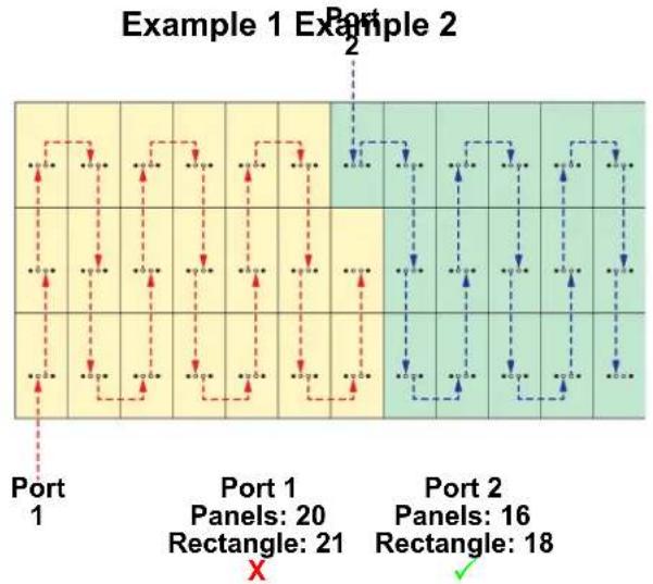
When panels are assembled together to output video from a VIP Drive 10-5 Nova or a VIP Drive 83R Nova, they form horizontal rows and vertical columns in rectangular arrangements.
Each port of one of the above mentioned VIP Drive products can connect to 20 F3X panels. If more than 20 panels are used, more than 1 output port from the VIP Drive will be required.
Pixels for each port are calculated as whole rectangles. Even if all panels within a rectangle are not connected to a port, the total panels in the rectangle must be within the limits of the port (less than 20). Connecting panels to a single port in an arrangement which creates a rectangle larger than 20 panels will cause errors and problems, even if only 20 panels are actually connected to that port.
Of the following examples, only those where both of the following are true can work:
- The number of panels connected to each port is equal to or less than 20.
• The panels connected to each port individually form a rectangle which includes 20 panels or fewer.
Connecting the Power Between Joined Panels
Power cable panel connections can also use different configurations. The basic configuration to connect the main power supply from one panel to the next is:
- The main power is connected to the first panel's Power Input or Output.
- A power cable is then connected to the first panel's Power Output and connected to the next panel's Power Input.
- The connections continue until all panels are connected.
Connect power between the panels using the same procedure as the signal only using the Power Input and Power Output connectors. Always adhere to the power-linking specifications for each F3X model. Refer to the Power Linking section for details on the number of panels that can be linked based on voltage from a single power connection.

Power linking more panels than recommended will void the product's warranty and increase the risk of electrocution or fire!
Refer to the following diagrams for an example of power connection from the main and to each connected panel.
This example is using the F3X power linking 5 panels horizontally @ 120 V.
![graph TD A["Power Linking Cable"] --> B["Main Power In"] B --> C["Grid 1"] B --> D["Grid 2"] B --> E["Grid 3"] B --> F["Grid 4"] G["Main Power In"] --> H["Grid 1"] G --> I["Grid 2"] G --> J["Grid 3"] G --> K["Grid 4"]](/content/2026/06/1229087/images/d714d246c190da4a658b377dc1229a0f95d4ea94910a538b29492826c092adf2.jpg)
7. LED Module Care and Replacement
F3X Modules
Each F3X has 4 LED modules connected to the panel frame by magnets. Each module has a single connector that connects to the main processing unit.
LED Lot Numbers
To ensure consistent color matching and output, replace damaged or defective modules with the same LED lot # as the others on the panel. When combining panels to create full video wall systems (rentals, permanent installations, etc.) it is highly recommended that the LED lot #'s on each of the panels match. LED lot #'s can be located on the back of each module.

A and B Modules
The F3X has 2 types of modules, designed to only plug in to the Service Module from one direction. Check the orientation of the LED LOT # label to determine whether the module is an A type (top half, connector down) or a B type (bottom half, connector up).

The arrows on each module point towards the top of the panel when correctly installed.
Calibration Recall
Each LED module for the F3X has individual calibration data for each LED permanently saved to the flash memory of the module. The receiver card inside the control box (or Service module) of the F3X can use that data to ensure a uniformity of brightness across the entire panel. To upload the calibration data from a new LED module to the Service Module of the panel, follow the instructions below.
Without a Computer
- Unplug any signal cables and power the product off.
- Hold the Test Button down and power the product on.
- Continue to hold the Test Button down for 10 seconds.
- Release the Test Button. The signal indicator will flash rapidly while it downloads the calibration data from the module.
- When the signal indicator stops flashing rapidly, the new module will have been matched automatically to the rest of the panel.
With a Computer
See the Novastar Troubleshooting Guide for instructions on how to perform a calibration recall with a computer.
F3X LED Module Removal
Removing a Module from the Rear
To remove an LED module from the rear of the F3X:
- Identify which module needs to be removed.
- Carefully grip the module by the handles from the rear of the panel assembly.
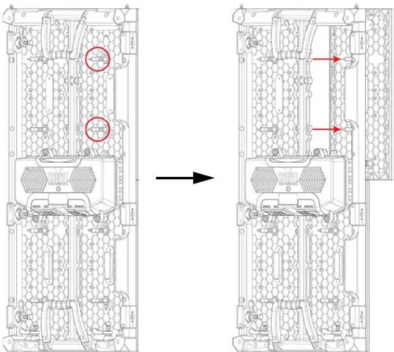
- With steadily increasing force and keeping as straight as possible, push the module forward away from the frame until it comes loose.

Use caution when removing the module so as not to damage the connector attached to the back of the module.
- Carefully tilt the module to pull it through to the rear, or have someone on the other side take it.
- Reverse the steps to install the replacement module.

WARNING! The magnets on the modules are very powerful! Keep fingers clear when installing.
Removing and Replacing the LED Masks

To replace one of the LED masks on an F3X LED module, follow the instructions below:
- Remove the module from the F3X (see F3X LED Module Removal).
- Remove the 20 screws securing the mask with a Phillips-head screwdriver.
- Gently lift the edges of the mask with a thin prying tool.


- A dull plastic prying tool is recommended to prevent LED damage.
- Bending the mask too much will permanently stretch it beyond usability.
• Take SPECIAL CARE to not pry off any LEDs!
- When in doubt, seek expert assistance or advice!
- Work the prying tool toward the center, gently lifting the mask from the LEDs.
- Place the new LED mask in the space, with the rear (clips and arrows) side facing in towards the product. Ensure the orientation arrows point in the same direction as the arrows on the module.
- Push the mask in firmly until it is completely flush with the rest of the masks on the product. A roller tool is recommended for this procedure.
- Secure in place with the 20 screws.
8. F3X Serviceability

The F3X service module can be accessed and serviced from either the front of the panel or the rear of the panel at any time, so panels can be serviced when access to either the front or the rear is restricted or impossible. Follow the instructions below to access the F3X service module from the front of the panel:

- Remove the modules as described in LED Module Care and Replacement.
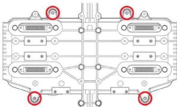
- Remove four Phillips-head screws.

Use caution when removing these screws, as the cover of the service module will be detached from the panel frame. All components in the service module are attached to the cover.
To access the F3X service module from the rear of the panel, remove the 4 screws indicated in the diagram below.


Use caution when removing these screws, as the cover of the service module will be detached from the panel frame. All components in the service module are attached to the cover.
9. Typical F3X Installation (Hanging)
Because a video wall system can include different components to provide a simple to complex modular wall design, use the following steps as a general guide to get started.
Step 1
Open and examine the F3X road case to make sure all products and accessories are present and that each one is in good condition.
Step 2
Apply power and run the self-test for each F3X to ensure all LEDs and inside connections in each panel are working (optional).
Step 3
Create a stable mounting surface (e.g., truss or other stable surface) for F3X mounting.
Step 4
Mount the first top row of the F3X products. Refer to the Mounting section in this User Manual.
Step 5
Adjust the alignment of the first row using the Speego connectors / latches.
Step 6
Connect the signal source to the VIP Drive 10-5 Nova or VIP Drive 83R Nova.
Step 7
Connect the VIP Drive to the Signal port of the first panel in the connection chain.
Step 8
Based on the desired video wall configuration (design), join each panel, horizontally and/or vertically, using the instructions in the section Joining Each F3X (Creating a Modular Design).
Refer to the instructions and information in the Connecting (Cabling) Each F3X section of this User Manual,
10. Operation
Additional Hardware and Software
In addition to the panels, the user will need other hardware and software to design, build, and operate the F3X video wall system. The following table summarizes these additional items—some are required and others are optional.
| Item Description | |
| VIP Drive 10-5 Nova or VIP Drive 83R Nova | Interface between the signal source, NovaLCT, and the F3X being used |
| NovaLCT and/or SmartLCT | Software applications used to design and run the F3X products comprising the video wall. A PC is needed |
| DRB-F50CM or DRB-F100CM F-Series Dual Function Rig Bar (optional) | Provides hardware needed to mount F3X |
| Neutrik® etherCON® Signal (optional) | Neutrik etherCON CAT6 extension cable, 18 in, 5 ft, 10 ft, 25 ft, and 50 ft |
| IP65 Rated Seetronic® Powerkon Extension (optional) | IP65 Rated Seetronic® Powerkon Extension, 5 ft, 10 ft, and 25 ft |
| VIP Media System Rack mountable video computer system | |
ArKaos MediaMaster Video playback software
About NovaLCT and SmartLCT
NovaLCT and SmartLCT are powerful and easy-to-learn software applications used to design and run the F3X video wall system. The following is some introductory information about these applications. Refer to the VIP Drive 10-5 Nova or VIP Drive 83R Nova User Manual for detailed information and instructions on setting up and using NovaLCT and SmartLCT with the Chauvet F3X video wall system.
Description
NovaLCT and SmartLCT enable the creation and control of a video wall by addressing the panels included in the video wall including pixel pitch and layout.
Once having physically created the modular video wall design by joining the panels, connecting power, signals, and the VIP Drive 10-5 Nova or VIP Drive 83R Nova, recreate that design within NovaLCT. Detailed information and instructions are in the User Manuals for the VIP Drive 10-5 Nova and the VIP Drive 83R Nova.

Chauvet does not recommend using NovaLCT or SmartLCT for live show playback. For this purpose, Chauvet offers Arkaos MediaMaster, which offers numerous playback triggers, including DMX, Art-Net, MA-net, MIDI, and QWERTY.
Receiver Card Configuration Files
Receiver Card Configuration Files, commonly referred to as RCFGX files, contain all of the data used to route video signal data from the receiver card to the LED drivers inside the F3X panels. This data includes:
• LED module layout and quantity
- LED driver model
- Scan mode (number of LEDs in a series)
- R e f r e s h r a t e
- Grayscale
• Maximum brightness
• Total panel orientation (when compatible)
• Gamma table (dimming curve)
• The signal indicator LED on/off function
- Panel power consumption
- Panel dimensions
- LED quantity
• LED module flash configuration
The RCFGX file does not contain brightness/chroma calibration data or mapping data (panel layout). Each of these are stored as separate files. To load a new RCFGX file onto an F3X panel, follow the steps under Updating RCFGX Files (NovaLCT) or Updating RCFGX Files (SmartLCT).

Ensure the RCFGX file version matches the firmware version on the panel.
Updating RCFGX Files (NovaLCT)
To update the RCFGX files of F3X products through NovaLCT:
- Connect the VIP Drive being used to a computer with NovaLCT installed.
- Open the NovaLCT software.
- Click User (U) in the menu running across the top of the window to open the drop-down menu.

- Click Advanced Synchronous System UserLogin(A).

- Type admin into the password field, and click the Login button on the screen, or press the Enter key.
- Open Screen Configuration.

- Select the appropriate communications port for the connected panel assembly from the drop-down list.

-
Click Next.
-
In the Screen Configuration window, navigate to the Receiving Card tab.

- Click Load from File.
- Select the RCFGX file to load. The latest version can be downloaded from www.chauvetvideo.com.
- When the file is loaded successfully, press OK to close the confirmation window.
Rotating the Video Panel Orientation (NovaLCT)
When mounting F3X panels sideways (90° or 270°), their orientation must be set in the mapping software. To do this through NovaLCT
- If the RCFGX files of the panels are up to date, follow steps 1-9 under Updating RCFGX Files (NovaLCT). If the RCFGX files are not up to date, follow steps 1-12.
- Click the Set Rotation hyperlink which appears in the upper right corner of the Cabinet Information section of the Receiving Card tab.
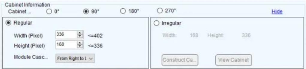
- Select either 90° or 270° to rotate the video within the connected panels.

The size of the Receiving Card will be changed accordingly from 128x256 to 256x128. If using the software to map a panel assembly, these values must be used as the Receiving Card parameters of the NovaLCT software.
Updating RCFGX Files (SmartLCT)
To update the RCFGX files of F3X products through SmartLCT.
- Connect the VIP Drive being used to a computer with SmartLCT installed.
- Open the SmartLCT software.
- Open a saved design or create a new design and map the products as needed.
- Select the desired products (of the same type) from the products which are mapped.

- Right click on one of the selected products (F6 Strip IP from Chauvet Professional shown for example purposes only).
- If one product is selected, Read back parameters can be selected, which will download the RCFGX file from that product to the computer.
- Select Update receiving card parameters.
- Click the button to the right of the field under From local rcfgx file, and browse to find and select the RCFGX file.

- Click Update.
11. Technical Information
F3X Maintenance
To maintain optimum performance and minimize wear, the user should clean this product regularly. Usage and environment are contributing factors in determining the cleaning frequency.
As a rule, clean this product at least twice a month. Dust build-up reduces light output performance and can cause overheating. This can lead to reduced light source life and increased mechanical wear.
To clean an F3X, follow the recommendations below:
- Unplug the panel from power.
- Wait until the product is at room temperature.
- Use a soft brush to remove dust collected on the external components.
- Wipe the outside of the LED Modules with a soft, lint-free cloth dampened with a solution of 99% isopropyl alcohol. ONLY apply gentle pressure, or risk damaging the anti-reflective coating.
- Make sure all connections are thoroughly dry before reconnecting power and signal cables.


Always dry the external surfaces carefully after cleaning them.
- ONLY apply gentle pressure, or risk damaging the anti-reflective coating.
- CAUTION! Take special care when using 99% isopropyl alcohol, as fumes may be harmful if inhaled. Vapors may cause drowsiness and dizziness. Keep away from sparks and flames.
12. Technical Specifications
Optical
| Light Source | Red Wavelength | Green Wavelength | Blue Wavelength |
| Tri-color RGB SMD 2121 LED 620 to 625 nm 512 to 532 nm 460 to 475 nm | |||
| Pixels per Panel Pixel Pitch | (between LEDs) | Pixel Density Display | Refresh Rate |
| 128 x 256 (32,768 total) 3.9 mm 65,536/m | 2 | 3,840 Hz (S-PWM) | |
| Viewing Angle Calibrated Illuminance Maximum Illuminance | |||
| (H/V) 140°/110° 1000 NITS | 1200 NITS | ||
Power
| Power Supply Type | AC Voltage Range | Voltage Selection | |
| Switching | 100–240 VAC, 50/60 Hz | Auto-ranging | |
| Parameter | 120 V, 60 Hz | 208 V, 60 Hz | 230 V, 50 Hz |
| Power Consumption | 305 W, 2.54 A | 305 W, 1.46 A | 305 W, 1.32 A |
| Power Linking | 5 units | 10 units | 11 units |
| Construction/Physical | |||
| Dimensions | Weight | |
| 19 x 39 x 2.5 in (500 x 1000 x 64 mm) | 30 lb (13.6 kg) | |
| Transparency | Housing Material | Operating Temperature |
| 0% | Magnesium die-cast | -4 °F to 131 °F (-20 °C to 55 °C) |
Connections
| Power Connection | Data Connection | Control Protocol |
| Seetronic Powerkon® IP65 | Seetronic Etherkon® IP65 | Novastar |
| Maximum Panels/VIP Drive 43Nova 2 | Notes for All Drives | |
| 20/port, 60/drive (4 ports) @ 1920x1080, 60 Hz | ||
| 20/port, 75/drive (4 ports) @ 1920x1280, 30/50 Hz | ||
| 20/port, 80/drive (4 ports) @ 1920x1536, 30 Hz | ||
| (up to 80/drive at any resolution if overlapping video content) | ||
| Maximum Panels/VIP Drive 83R Nova |
| 20/port, 90/drive (8 ports) @ 1920x1536, 30 Hz |
| 20/port, 120/drive (8 ports) @ 3840x1080, 30 Hz(up to 160/drive at any resolution if overlapping video content) |
| Maximum Panels/VIP Drive 10-5 Nova |
| 20/port, 120/drive (10 ports) @ 3840x1080, 60 Hz |
| 20/port, 180/drive (10 ports) @ 3840x2160, 30 Hz(up to 200/drive at any resolution if overlapping video content) |
| Max. Wide/VIP Drive 43Nova 215 @ 1920 wide resolution | Max. Wide/VIP Drive 83R Nova30 @ 3840 wide resolution | Max. Wide/VIP Drive 10-5 Nova30 @ 3840 wide resolution |
| Max. Tall/VIP Drive 43Nova 2 | Max. Tall/VIP Drive 83R Nova | Max. Tall/VIP Drive 10-5 Nova |
| 3 @ 1920x1080, 30/50/59.94/60 Hz4 @ 1920x1080, 60 Hz4 @ 1920x1280, 30/50 Hz5 @ 1920x1080, 30/50 Hz6 @ 1920x1080, 30 Hz6 @ 1920x1536, 30 Hz | 3 @ 1920x1080, 30/50/59.94/60 Hz4 @ 3840x1080, 60 Hz4 @ 1920x1280, 30/50 Hz5 @ 3840x1080, 30/50 Hz6 @ 1920x1536, 30 Hz6 @ 3840x1080, 30 Hz | 4 @ 3840x1080, 60 Hz8 @ 3840x2160, 30 Hz |
Ordering
| Product Name | Item Name | Item Code | UPC Number |
| F3X (4-Pack Road Case) | F3XX4 | 23091316 | 781462216641 |

UL 62368-1 ® CSA C22.2 No. 62368-1 IS E114016


RoHS
Contact Us
General Information Technical Support
Chauvet World Headquarters
Address: 3360 Davie Rd. Voice: (844) 393-7575
Davie, FL 33314 Fax: (954) 756-8015
Voice: (954) 577-4455 Email: chauvetcs@chauvetlighting.com
Fax: (954) 929-5560
Toll Free: (800) 762-1084 Website: www.chauvetprofessional.com
Chauvet Europe Ltd
Address: Pod 1 EVO Park Email: UKtech@chauvetlighting.eu
Little Oak Drive
Sherwood Park, Nottinghamshire, U.K. Website: www.chauvetprofessional.eu
NG15 OEB
Voice: +44 (0) 1773 511115
Fax: +44 (0) 1773 511110
Chauvet Europe BVBA
Address: Stokstraat 18 Email: BNLtech@chauvetlighting.eu
9770 Kruishoutem
Belgium Website: www.chauvetprofessional.eu
Voice: +32 9 388 93 97
Chauvet France
Address: 3, Rue Ampère
91380 Chilly-Mazarin
France Website: www.chauvetprofessional.eu
Voice: +33 1 78 85 33 59
Chauvet Germany
(Entrance by Calle 2)
Email: servicio@chauvet.com.mx
Zona Industrial Lerma Website: www.chauvetprofessional.mx
Visit the applicable website above to verify our contact information and instructions to request support. Outside the U.S., U.K., Ireland, Benelux, France, Germany, or Mexico, contact the dealer of record.
Warranty & Returns
For warranty terms and conditions and return information, please visit our website.
For customers in the United States and Mexico: www.chauvetlighting.com/warranty-registration.
For customers in the United Kingdom, Republic of Ireland, Belgium, the Netherlands, Luxembourg, France, and Germany: www.chauvetlighting.eu/warranty-registration.
- EDITION NOTES
- TRADEMARKS
- COPYRIGHT NOTICE
- MANUAL USE
- DOCUMENT PRINTING
- INTENDED AUDIENCE
- DISCLAIMER
- DOCUMENT REVISION
- TABLE OF CONTENTS
- BEFORE YOU BEGIN .... 1
- INTRODUCTION ...... 3
- SETUP 7
- MOUNTING 8
- JOINING EACH F3X (CREATING A MODULAR DESIGN) 15
- CONNECTING (CABLING) EACH F3X.... 18
- LED MODULE CARE AND REPLACEMENT.... 22
- F3X SERVICEABILITY.... 25
- TYPICAL F3X INSTALLATION (HANGING)...... 27
- OPERATION 28
- TECHNICAL INFORMATION 32
- TECHNICAL SPECIFICATIONS .... 33
- CONTACT US 34
- BEFORE YOU BEGIN
- WHAT IS INCLUDED
- CLAIMS
- TEXT CONVENTIONS
- SYMBOLS
- SAFETY NOTES
- PERSONAL SAFETY
- MOUNTING AND RIGGING
- POWER AND WIRING
- OPERATION
- EXPECTED LED LIFESPAN
- INTRODUCTION
- PRODUCT DESCRIPTION
- FEATURES
- REQUIRED ACCESSORIES
- OPTIONAL ACCESSORIES
- AVAILABLE SIGNAL AND POWER CABLES
- PIXELS PER PANEL
- SCRAMBLED PULSE-WIDTH MODULATION
- SETUP
- AC POWER
- AC PLUG
- MOUNTING
- ORIENTATION
- MOUNTING POINTS
- MOUNTING WITH DUAL FUNCTION RIG BAR (HANGING)
- TRUSS INSTALLATION
- MOUNTING WITH DUAL FUNCTION RIG BAR (STACKING)
- REMOVING THE FEET
- FLAT WALL INSTALLATION
- MOUNTING POINTS ON A FLAT WALL
- MOUNTING WITH STEEL STRUTS
- SPACERS (FLAT WALL INSTALLATION)
- JOINING EACH F3X (CREATING A MODULAR DESIGN)
- VERTICALLY JOINING THE PANELS
- VERTICAL PANEL CONNECTION
- HORIZONTALLY JOINING THE PANELS
- HORIZONTAL PANEL CONNECTION
- CONNECTING (CABLING) EACH F3X
- TESTING SIGNAL AND POWER CONNECTIONS
- USING THE F3X TEST BUTTON
- CONNECTING POWER AND SIGNAL CABLES
- CONNECTING THE SIGNAL BETWEEN JOINED PANELS
- CUSTOM RESOLUTIONS
- EXAMPLE
- SIGNAL CHAIN RECTANGLES
- CONNECTING THE POWER BETWEEN JOINED PANELS
- POWER LINKING MORE PANELS THAN RECOMMENDED WILL VOID THE PRODUCT'S WARRANTY AND INCREASE THE RISK OF ELECTROCUTION OR FIRE
- LED MODULE CARE AND REPLACEMENT
- F3X MODULES
- LED LOT NUMBERS
- A AND B MODULES
- CALIBRATION RECALL
- WITHOUT A COMPUTER
- WITH A COMPUTER
- F3X LED MODULE REMOVAL
- REMOVING A MODULE FROM THE REAR
- REMOVING AND REPLACING THE LED MASKS
- F3X SERVICEABILITY
- TYPICAL F3X INSTALLATION (HANGING)
- STEP 1
- STEP 2
- STEP 3
- STEP 4
- STEP 5
- STEP 6
- STEP 7
- STEP 8
- ADDITIONAL HARDWARE AND SOFTWARE
- ABOUT NOVALCT AND SMARTLCT
- DESCRIPTION
- RECEIVER CARD CONFIGURATION FILES
- UPDATING RCFGX FILES (NOVALCT)
- ROTATING THE VIDEO PANEL ORIENTATION (NOVALCT)
- UPDATING RCFGX FILES (SMARTLCT)
- TECHNICAL INFORMATION
- F3X MAINTENANCE
- TECHNICAL SPECIFICATIONS
- CONTACT US
- GENERAL INFORMATION TECHNICAL SUPPORT
- CHAUVET WORLD HEADQUARTERS
- CHAUVET EUROPE LTD
- CHAUVET EUROPE BVBA
- CHAUVET FRANCE
- CHAUVET GERMANY
- WARRANTY & RETURNS
Brand : Chauvet
Model : F3X
Category : Tracking