
PFV1405XW - Freezer Premium - Free user manual and instructions
Find the device manual for free PFV1405XW Premium in PDF.

| Type | Freezer |
| Brand | Premium |
| Model | PFV1405XW |
| Width | 71.0 cm (27.95 in) |
| Height | 172.8 cm (68.03 in) |
| Depth | 70.9 cm (27.89 in) |
| Temperature Range | -28°C to 8°C (-18°F to 46°F) |
| Defrost Type | Automatic |
| Refrigerant | Flammable (R600a) |
| Control Panel | Electronic with digital display, mode selection, and temperature adjustment |
| Door Alarm | Yes, sounds after 3 minutes of door being open |
| Handle | Included, requires installation |
| Leveling Legs | 2 adjustable legs |
| Number of Glass Shelves | 4 |
| Lower Drawer | 1 |
| Door Shelves | 4 |
| Installation Type | Freestanding |
| Clearance Required | 12.7 cm (5 in) on back, sides, and top |
| Compressor Resistance | C-M: 5.67-6.93 Ω, C-S: 6.03-7.37 Ω, S-M: 11.70-14.30 Ω |
| PTC Starter Resistance | 3.5-5.8 Ω (model QPE2-A4R7MD3) |
Frequently Asked Questions - PFV1405XW Premium
User questions about PFV1405XW Premium
0 question about this device. Answer the ones you know or ask your own.
Ask a new question about this device
Download the instructions for your Freezer in PDF format for free! Find your manual PFV1405XW - Premium and take your electronic device back in hand. On this page are published all the documents necessary for the use of your device. PFV1405XW by Premium.
USER MANUAL PFV1405XW Premium
USING INTRODUCTION ....6\~9
DISASSEMBLY COMMON PARTS OF REFRIGERATOR....10\~20
◆ CARE & MAINTENANCE
◆ Checking the compressor and replacing PTC and Overload protector
◆ Compressor Capacitor install and removal
EXPLODED DRAWING 21
TROUBLESHOOTING....22
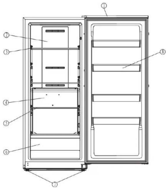
PARTS IDENTIFICATION
- Door
- Upper air duct plate
- Glass shelf I
- Lower air duct board
- Glass shelf II
- Lower drawer
- Adjustable Feet
- Door shelf
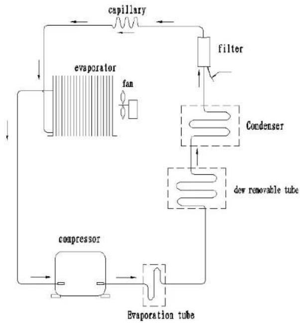
Basic refrigeration schematic
flowchart
graph TD
    A["evaporator"] --> B["capillary"]
    B --> C["filter"]
    C --> D["condenser"]
    D --> E["dew removable tube"]
    E --> F["evaporation tube"]
    F --> G["compressor"]
    G --> H["fan"]
    H --> A
CIRCUIT DIAGRAM

flowchart
graph TD
    A["RUNNING CAPACITOR"] --> B["PTC STARTER"]
    B --> C["PTC"]
    C --> D["S M COMPRESSOR"]
    D --> E["yellow / green OVERLOAD PROTECTOR"]
    E --> F["red"]
    F --> G["CONTROL BOARD"]
    G --> H["CN1"]
    G --> I["CN2"]
    G --> J["CN3"]
    G --> K["CN6"]
    G --> L["SWITCH"]
    G --> M["LED LAMP"]
    G --> N["EVAPORATOR FAN MOTOR"]
    G --> O["GREEN"]
    G --> P["THERMAL FUSE"]
    G --> Q["THERMAL FUSE"]
    G --> R["H N"]
    G --> S["H N"]
    G --> T["DEFROST HEATER"]
    G --> U["REFRIGERATOR SENSOR"]
    G --> V["EVAPORATOR SENSOR"]
    G --> W["DISPLAY BOARD"]
SAFETY PRECAUTIONS
AFETY REQUIREMENTS
DANGER: Risk of fire or explosion. Flammable refrigerant used. Do not puncture refrigerant tubing.
- Do not use mechanical devices to defrost refrigerator.
- Ensure that servicing is done by factory authorized service personnel, to minimize product damage or safety issues.
- If the power supply cord is damaged, it must be replaced by the manufacturer, its service agent or similar qualified person in order to avoid hazard.
- Consult repair manual or owner's guide before attempting to service this product. All safety precautions must be followed.
- Dispose of properly in accordance with federal or local regulations.
- Follow handling instructions carefully.
- Do not store explosive substances such as aerosol cans with a flammable propellant in this appliance.
WARNING: Keep ventilation openings, in the appliance enclosure or in the built-in structure, clear of obstruction.
WARNING: Do not use mechanical devices or other means to accelerate the defrosting process, other than those recommended by the manufacturer.
WARNING: Do not damage the refrigerant circuit.
WARNING: Do not use electrical appliances inside the food storage compartments of the appliance, unless they are of the type recommended by the manufacturer.
CAUTION: Risk of fire or explosion. Flammable refrigerant used.
CAUTION: Children should be supervised to ensure that they do not play with the appliance.
DANGER: Risk of child entrapment. Before throwing
away an old appliance:
- Remove the door or lid.
- Leave shelves in place so that children may not easily climb inside.
DANGER: Do not add a lock to the door or lid. This can cause child entrapment and harm.
SAFETY REQUIREMENTS
This appliance is not intended for use by persons (including children) whose physical, sensory or mental capabilities may be different or reduced, or who lack experience or knowledge, unless such persons receive supervision or training to operate the appliance by a person responsible for their safety.
This appliance is intended to be used in household and similar applications such as:
- Staff kitchen areas in shops, offices and other working environments;
- Farm houses and by clients in hotels, motels and other residential type environments;
- Bed and breakfast type environments;
- Catering and similar non-retail applications.
GROUNDING INSTRUCTIONS
This appliance must be grounded. Grounding reduces the risk of electrical shock by providing an escape wire for the electrical current. This appliance has a cord that has a grounding wire with a 3-prong plug. The power cord must be plugged into an outlet that is properly grounded.
If the outlet is a 2-prong wall outlet, it must bereplaced with a properly grounded 3-prong walloutlet. The serial rating plate indicates the voltage and frequency the appliance is designed for.
WARNING - Improper use of the grounding plug can result in a risk of electric shock. Consult a qualified electrician or service agent if the grounding instructions are not completely understood, or if doubt exists as to whether the appliance is properly grounded.
Do not connect your appliance to extension cords or together with another appliance in the same wall outlet. Do not splice the power cord.
Do not under any circumstances cut or remove the third ground prong from the power cord. Do not use extension cords or ungrounded (two prongs) adapters.
If the power supply cord is damaged, it must be replaced by the manufacturer, its service agent or similar qualified person in order to avoid hazard.
USING INTRODUCTION
LOCATION
- Two people should be used when moving the appliance.
- Remove interior and exterior packaging prior to installation. Wipe the outside of the appliance with a soft, dry cloth and the inside with a lukewarm wet cloth.
- Place the appliance on a floor that is strong enough to support it when it is fully loaded.
- Do not place the appliance in direct sunlight or near sources of heat, such as a stove or heater, as this can increase electrical consumption.
Extreme cold ambient temperatures may also cause the appliance to perform improperly.
- Do not use the appliance near water, for example in a wet basement or near a sink.
- This appliance is intended for indoor household only. It is not designed for outside installation, including anywhere that is not temperature controlled such as porches, vehicles, etc.
- Before connecting the appliance to a power source, let it stand upright for approximately 6 hours. This will reduce the possibility of a malfunction in the cooling system from handling during transportation.
- This appliance is 71.0 cm (27.95 inches) wide by 172.8cm (68.03 inches) high by 70.9 cm(27.89 inches) deep. Make sure that you leave the minimum amount of space between the appliance and all surrounding walls and vents.Do not cover any of the ventilation openings with any material as the appliance needs adequate space to breathe.
- Allow 12.7 cm (5 inches) of space between the back, sides and top of the appliance and all adjacent walls.
- This appliance is intended for free-standing installation only and is not intended to be built into a cabinet or counter. Building in this appliance can cause it to malfunction.
LEVELING INSTRUCTIONS
There are two adjustable legs on the bottom of the appliance that can be turned up or down to ensure that the appliance is level.
-
Turn the leveling leg counter-clockwise as far as it will go, until the top of the foot is touching the bottom of the chassis.
-
Slowly turn the leveling leg clockwise until the appliance is level.

CONTROL PANEL

TEMPERATURE SETTING
When the temperature display is display will extinguish automatically after three minutes. When the display is extinguishing, press the keys to activate it, then key function will start work. Below operating instruction only applies to the display is unlocked
- Press the arrow buttons to set or adjust the temperature.
- "MODE", the operating mode will change and keep flashing when you press it. If no further action within 5 seconds, the current setting will take effect. The operating mode switch as follow: "FRIDGE"—"SUBZERO"—"FREEZE"—"FASTFREEZE"—"FRIDGE"
- " °F /°C", Tap the key, it will switch between the centigrade and Fahrenheit. The panel will lock if keep pressing " °F /°C" for 3 seconds. To unlock it, press " °F /°C" for 3 seconds.
• TEMPERATURE SCALE
"FRIDGE": 0°C\~8°C (32°F\~46°F)
"SUBZERO": -4°C\~-8°C (24°F\~17°F)
"FREEZE": -14ircC -24ircC(7ircF -11ircF)
"FASTFREEZE": -18ircC -28ircC(0ircF -18ircF)
OPEN DOOR ALARM
This appliance is equipped with a door alarm that will sound if the door is left open for more than 3 minutes. The alarm will beep and the display will flash continuously until the door is closed.
HANDLE INSTALLATION
The appliance ships with the handle inside the cabinet to protect it from damage. It must be installed by the end user. The appliance should be unplugged before installing the handle.
- Position the handle over the exposed doorhandle posts.
- Remove the two screws from the side of door with a screwdriver, insert screws into the handle bracket, fi x it to the side of door and tighten it until snug.
Note: The handle may look slightly different based on the colour of the appliance.
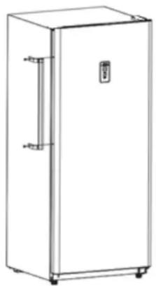
natural_image
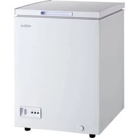
Line drawing of a single refrigerator with a door and side arm (no text or symbols)OUTER DIMENSIONS
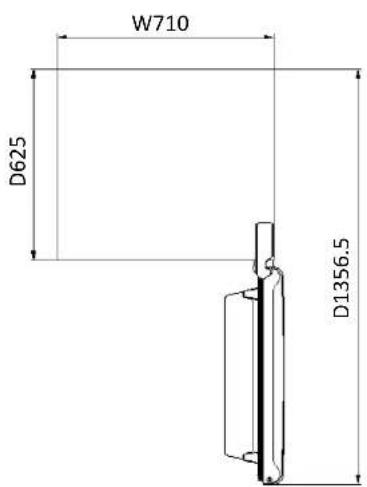

natural_image
Simple line drawing of a rectangular enclosure with base and top dimensions labeled H1728 (no text or symbols on the diagram itself)CARE & MAINTENANCE
CLEANING
Ensure the appliance is unplugged before cleaning.
- To clean the inside of the appliance, use a soft cloth and a solution of a tablespoon of baking soda to one quart of water or a mild soapsolution or some mild detergent.
- Wash removable shelves in a mild detergent solution, then dry and wipe with a soft cloth.
- Clean the outside with a soft, damp cloth and some mild detergent.
- It is important to keep the area clean where the door seals against the cabinet. Clean this area with a soapy cloth. Rinse with a damp cloth and let dry.
Note: Do not use cleaners containing ammonia or alcohol on the appliance. Ammonia or alcohol can damage the appearance of the appliance. Never use any commercial or abrasive cleaners or sharp objects on any part of the appliance.
DISASSEMBLY COMMON PARTS OF REFRIGERATOR
CARE & MAINTENANCE
POWER FAILURE
Most power failures are corrected within a few hours and should not affect the temperature of your appliance if you minimize the number of times the door is opened. If the power is going to be off for a longer period of time, take the proper steps to protect your contents.
Note: Wait 3 to 5 minutes before attempting to restart the refrigerator if operation has been interrupted.
DEFROST
This unit is equipped with an automatic defrost function and does not require manual defrosting. Defrost water from the appliance is channeled into a drip tray located above the compressor. Heat transfer from the compressor causes the defrost water to evaporate.
VACATION
- Short vacations: Leave the appliance operating during vacations of less than three weeks.
- Long vacations: If the appliance will not be used for several months, remove all items and turn off the appliance. Clean and dry the interior thoroughly. To prevent odor and mold growth, leave the door open slightly, blocking it open if necessary.
DISASSEMBLY COMMON PARTS OF REFRIGERATOR
CARE & MAINTENANCE
ENERGY SAVING TIP
The appliance should be located in the coolest area of the room, away from heat producing appliances, and out of direct sunlight. Do not overload the unit or block any ventilation openings.
MOVING
- Remove all items.
- Tape the door shut.
- Be sure the appliance stays secure in the upright position during transportation. Also protect the outside of the appliance with a blanket or similar item.
- If the appliance is placed on its back or side during transportation, upon reaching the destination, allow it to remain in its operating position for 6 hours to avoid damage to internal components.
DISPOSAL
This appliance may not be treated as regular household waste, it should be taken to the appropriate waste collection point for recycling of electrical components. For information on local waste collection points, contact your local waste removal agency or government office.
DISASSEMBLY COMMON PARTS OF REFRIGERATOR
CARE & MAINTENANCE
ERROR CODES
• E1: The freezer sensor failure
• E2: Freezer defrosting sensor failure
• E3: The freezer sensor failure and freezer defrosting sensor failure
• CO: Communication failure
- dr: Door opening alarm
• EH: Freezer high temperature
- EL: Freezer low temperature
• H1: The freezer heater failure
DISASSEMBLY COMMON PARTS OF REFRIGERATOR
CARE & MAINTENANCE

stainless screw
Temperature control probe cover
Sensor
Lower Air Duct Plate screw
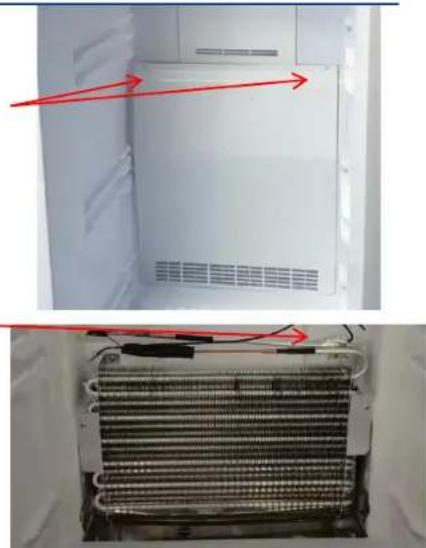
natural_image
Interior view of a refrigerator showing the exterior and side view of the internal structure (no text or symbols visible)Defrosting sensor
- Remove the stainless screw
- Remove the temperature control probe cover
-
Remove the Sensor and replace the Sensor
-
Remove the Lower Air Duct Plate screw
- Remove the Defrosting sensor and replace the Defrosting sensor
DISASSEMBLY COMMON PARTS OF REFRIGERATOR
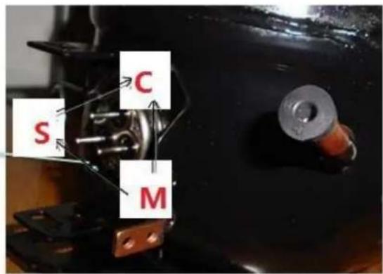
Checking the compressor
Resistance range at 25°C:
Resistance between C and M 5.67\~6.93Ω(6.3Ω±10%);
Resistance between C and S 6.03\~7.37Ω(6.70Ω±10%);
Resistance between S and M 11.70\~14.30Ω(13.00Ω±10%)

DISASSEMBLY COMMON PARTS OF REFRIGERATOR
Checking the compressor accessory
Disassemble the PTC starter and Over loaded Protector
- Remove the PTC and OLP components separately
- Use a flat-head screwdriver against the hook of the OLP, then press it down
- When the clip is unhooked, the PTC and OLP can be separated

natural_image
Close-up of a black plastic electronic component with internal wiring and connectors (no visible text or symbols)
natural_image
Close-up of a mechanical component with red and green arrows indicating directional movement (no text or symbols)
natural_image
Close-up of a white electrical connector with metallic pins and a central metallic component (no visible text or symbols)
natural_image
Close-up of a black plastic mechanical component with a metal bracket and mounting bracket (no visible text or symbols)DISASSEMBLY COMMON PARTS OF REFRIGERATOR
Checking the compressor accessory
Compressor Protector test ——
Use a multi-meter to test the resistance between the two end as the pic show :
If there show 000 or almost 0 then it is OK.
If there is no response then it is broken.
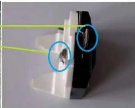
natural_image
Close-up of a mechanical component with highlighted circular features (no text or symbols visible)Checking the compressor accessory
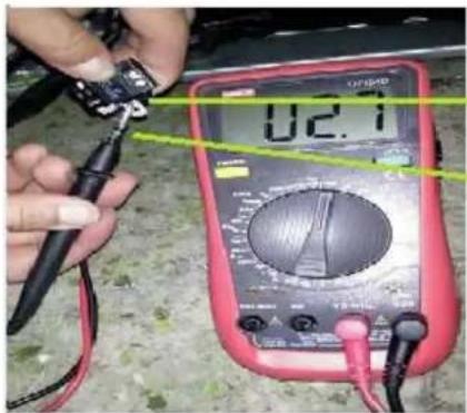
Compressor PTC starter test ——
Use a multi-meter to test the resistance between the two end as the pic show
If there show the number is between about 3.5-5.8 then it is OK.
If there show 000 or no response then it is broken.
After the replacement of the PTC and OLP, the compressor still does not start.
If there is no exhaust, the compressor is fault.
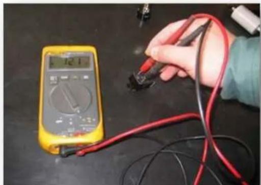
natural_image
Hand holding a multimeter measuring a test strip with red and black wires (no visible text or symbols)PTC starter:QPE2-A4R7MD3
DISASSEMBLY COMMON PARTS OF REFRIGERATOR
The instruction of replacing PTC and Overload protector
- Remove the fastening screws
- Remove the Compressor Wire Clamp Screw and Compressor Wire Clamp
- Remove the cover
- Replace the PTC Starter & OLP

DISASSEMBLY COMMON PARTS OF REFRIGERATOR
Compressor Capacitor install and removal
Install Capacitor:
- M-type clip is aligned with the rectangular hole on the compressor baseplate
- Press down hard till hear a "ding"
- Check whether the capacitor is fastened or not
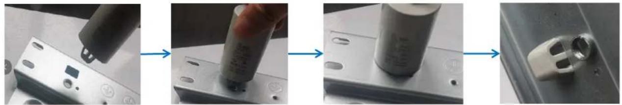
Remove Capacitor:
- Place the freezer sideways until you can see the compressor baseplate
- Clamp the capacitor M-type clap with plier and press it in slightly.
- When the M-type clap is unhooked, you can remove the capacitor.

EXPLODED DRAWING
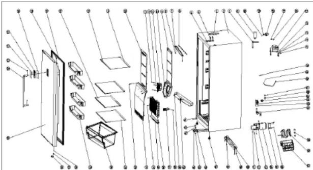
| 1 | Filter | 1 | 11 Dc fan | 1 |
| 2 | Tank shell | 1 | 12 Gasket | 3 |
| 3 | Hinged cover | 1 | 13 B45 Stainless steel (3.5x13) | 3 |
| 4 | Belt pad machine (M6X14) | 4 | 14 Upper hand but | 1 |
| 5 | On the hinge 1 | 15 Glass shelf rear trim strip | 4 | |
| 6 | LED lamp | 1 | 16 Glass shelf front trim strip | 4 |
| 7 | LED chimney | 1 | 17 Glass shelf II 1 | |
| 8 | Self lapping screw (ST3.9X160 | 2 | 18 Door gasket | 1 |
| 9 | Upper duct foam | 1 | 19 Upper hinge sleeve | 1 |
| 10 Fan cover | 1 | |||
| 20 Display panel 1 | 40 Flow plate | 1 | 62 Drainage elbow | 1 | ||||
| 21 Display plate 1 | 41 Cap nail | 2 | 63 Self tapping screw(4x12) | 2 | ||||
| 22 According to the face 1 | 42 Hinge gasket | 1 | 64 Drain connection pipe | 1 | ||||
| 23 B19 Stainless steel (5x16) 2 | 43 Hinge base | 1 | 65 Exhaust cover 1 | |||||
| 24 White side door handle 1 | 44 Padded machine tapping | 4 | 66 Exhaust cover plates | 1 | ||||
| 25 Hydrodynamic 1 | 45 M8 Nut 1 | 67 Exhaust cover fixing column | 1 | |||||
| 26 Threshold a piece 1 | 46 Lower hinge | 1 | 68 Power cord | 1 | ||||
| 27 Lower door axis sheath 1 | 47 Adjustable foot | 2 | 69 | 818Machine attack(ROHS)4X8(With gear washer) | 1 | |||
| 28 Big flat head attack(ROHS)4x12 1 | 48 Self tapping screw(4x12) | 4 | ||||||
| 70 Ground wire | 1 | |||||||
| 29 Upper door rack 4 | 49 Compressor base plate | 1 | ||||||
| 71 Rubber wire | 4 | |||||||
| 30 Drawer 1 | 50 Wheel cobalt | 2 | ||||||
| 72 Bushing | 4 | |||||||
| 31 Glass shelf I | 3 | 51 Screw | 1 | |||||
| 73 Washer | 4 | |||||||
| 32 845 Stainless steel (Large flathead)4x12 | 2 | 52 Electric control board | 1 | |||||
| 74 Belt(M6X30) | 4 | |||||||
| 33 Lower air duct board | 1 | 53 Electric control box cover | 1 | |||||
| 75 Compressor | 1 | |||||||
| 34 845 Stainless steel (4.2x16) | 2 | 54 Electric control box | 1 | |||||
| 76 Starter | 1 | |||||||
| 35 Heating tube | 1 | 55 | Fixed connector of main controlboard | 1 | ||||
| 77 Overload protector | 1 | |||||||
| 36 Evaporator | 1 | 56 Self tapping screw(4x12) | 4 | 78 Housing | 1 | |||
| 37 Probe cover | 1 | |||||||
| 57 Water tray | 1 | 79 Clamp(FZ40C1J-U) | 1 | |||||
| 38 845 Stainless steel (ST3.9x16) | 1 | 58 Water removal evaporation pipe 1 | 80 Self tapping screw(ST3.5X19) | 1 | ||||
| 39 818Machine attack(ROHS)4X8(With gear washer) | 1 | 59 Damping rubber block | 3 | 81 Capacitance | 1 | |||
TROUBLESHOOTING
| PROBLEM | POSSIBLE CAUSE |
| No power | A fuse may be blown or the circuit breaker trippedPlug not fully inserted into the wall outlet |
| Internal temperature not cold enough | Temperature setting is too warmDoor is not shut properly or opened excessivelyExhaust vent is obstructedRecently added a large quantity of warm food to the cabinetClose proximity to heat source or direct sunlightAmbient temperature or humidity is very high |
| Appliance runs continuously | Temperature setting is too coldDoor not shut properly or opened excessivelyExhaust vent is obstructedRecently added a large quantity of warm food to the cabinetClose proximity to heat source or direct sunlightAmbient temperature or humidity is very high |
| Internal temperature is too cold | Temperature setting is too cold |
| Noises | Parts are expanding and/or the refrigerant is circulating; this is normal |

- PARTS IDENTIFICATION
- SAFETY PRECAUTIONS
- AFETY REQUIREMENTS
- SAFETY REQUIREMENTS
- GROUNDING INSTRUCTIONS
- USING INTRODUCTION
- LOCATION
- LEVELING INSTRUCTIONS
- TEMPERATURE SETTING
- OPEN DOOR ALARM
- HANDLE INSTALLATION
- OUTER DIMENSIONS
- CARE & MAINTENANCE
- CLEANING
- DISASSEMBLY COMMON PARTS OF REFRIGERATOR
- POWER FAILURE
- DEFROST
- VACATION
- ENERGY SAVING TIP
- MOVING
- DISPOSAL
- ERROR CODES
- Checking the compressor
- Checking the compressor accessory
- The instruction of replacing PTC and Overload protector
- Compressor Capacitor install and removal
- Install Capacitor:
- Remove Capacitor:
- EXPLODED DRAWING
- TROUBLESHOOTING
Brand : Premium
Model : PFV1405XW
Category : Freezer