
Erling - Fan HUNTER - Free user manual and instructions
Find the device manual for free Erling HUNTER in PDF.

| Product Type | Ceiling Fan |
| Brand | Hunter |
| Model | Erling |
| Model Numbers | 52849 (Luxe Gold), 52850 (Matte Black), 52851 (Fresh White) |
| Weight | 16.8 lbs (7.6 kg) |
| Motor Type | DC Motor |
| Remote Control | Included with CR2032 battery |
| Light Kit | Integrated LED (included) |
| Airflow Reversible | Yes (downdraft and updraft) |
| Warranty | Limited Lifetime on motor, 3-year on other parts |
| Safety Certification | UL Listed / Intertek |
| Installation Type | Standard downrod mount; compatible with angled ceilings up to 34° (angled mounting kit required above 34°) |
| Downrod Included | Yes (pre-assembled) |
| Tools Required | Ladder, screwdriver, pliers, drill, 9/64" drill bit |
| Light Source | Integrated LED |
| Voltage | 120 V (standard US household) |
| Cleaning Instructions | Use soft brushes or cloths; avoid abrasive cleaners |
| Battery Type (Remote) | CR2032 (3V) |
Frequently Asked Questions - Erling HUNTER
User questions about Erling HUNTER
0 question about this device. Answer the ones you know or ask your own.
Ask a new question about this device
Download the instructions for your Fan in PDF format for free! Find your manual Erling - HUNTER and take your electronic device back in hand. On this page are published all the documents necessary for the use of your device. Erling by HUNTER.
USER MANUAL Erling HUNTER
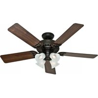
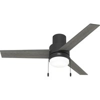
natural_image
Black-and-white photo of a modern office ceiling with a large wooden pendant light and four blades, placed on a bed with pillows (no text or symbols visible)Erling
Installation Manual
Model: 52849 Luxe Gold
52850 Matte Black
52851 Fresh White
Fan weight ±2 lbs: 16.8 lbs (7.6 kg)

Hunter
©2024 Hunter Fan Co.
PG4188 r041224
The ceiling fan you purchased will provide comfort and performance in your home or office for many years. This instruction manual contains complete instructions for installing and operating your fan. We are proud of our work and appreciate the opportunity to supply you with the best ceiling fan available anywhere in the world.
We are here to help!
This Instruction Manual is designed to make installation as simple as possible. While working through this Instruction Manual, keep your smartphone or tablet nearby. We have added video links to help you through the more technical sections. If you are unfamiliar or uncomfortable with wiring, contact a qualified electrician. We also provide telephone support at 1.888.830.1326 or visit us at HunterFan.com.

READ and SAVE These Instructions
WARNING
Warning


w.1 - To reduce the risk of fire, electrical shock, or personal injury, mount fan directly from building structure and/or an outlet box marked acceptable for fan support of 70 lbs (31.8 kg) and use the mounting screws provided with the outlet box.
w.2 - To avoid possible electrical shock, before installing or servicing your fan, disconnect the power by turning off the circuit breakers to the outlet box and associated wall switch location. If you cannot lock the circuit breakers in the off position, securely fasten a prominent warning device, such as a tag, to the service panel.
w.3 – To reduce the risk of electric shock, this fan must be installed with an isolating wall control/switch.
w.4 - To reduce the risk of personal injury, do not bend the blade brackets when installing the blade brackets, balancing the blades, or cleaning the fan. Do not insert foreign objects in between rotating fan blades.
w.5 - Chemical burn hazard. Keep batteries away from children. This remote contains a lithium button cell battery. If a new or used lithium button/coin cell battery is swallowed or enters the body, it can cause severe internal burns and can lead to death in as little as 2 hours. Always completely secure the battery compartment. If the battery compartment does not close securely, stop using the product, remove the batteries, and keep it away from children. If you think batteries might have been swallowed or placed inside any part of the body, seek immediate medical attention. Dispose of cells properly and keep away from children. Even used cells may cause injury.
w.6 - Non-rechargeable batteries are not to be recharged. Exhausted batteries are to be removed from the product.
w.7 - This appliance can be used by children aged from 8 years and above and persons with reduced physical, sensory or mental capabilities or lack of experience and knowledge if they have been given supervision or instruction concerning use of the appliance in a safe way and understand the hazards involved. Children shall not play with the appliance. Cleaning and user maintenance shall not be made by children without supervision. It is recommended that children be supervised to ensure that they are not using the appliance improperly.
w.8 - To reduce the risk of fire or electric shock or injury to persons, do not use replacement parts that have not been recommended by the manufacturer (e.g. parts made at home using a 3D printer).
Caution
c.1 - All wiring must be in accordance with national and local electrical codes ANSI/NFPA 70. If you are unfamiliar with wiring, use a qualified electrician.
c.2 - Use only Hunter replacement parts.
This equipment has been tested and found to comply with the limits for a Class B digital device, pursuant to part 15 of the FCC Rules. These limits are designed to provide reasonable protection against harmful interference in a residential installation. This equipment generates, uses and can radiate radio frequency energy and if not installed and used in accordance with the instructions may cause harmful interference to radio communications.
However, there is no guarantee that interference will not occur in a particular installation. If this equipment does cause harmful interference to radio or television reception, which can be determined by turning the equipment off and on, the user is encouraged to try to correct the interference by one or more of the following measures:
- Reorient or relocate the receiving antenna.
- Increase the separation between the equipment and receiver.
- Connect the equipment into an outlet on a circuit different from that to which the receiver is connected.
- Consult the dealer or an experienced radio/TV technician for help.
Caution: modifications not approved by the party responsible for compliance could void user's authority to operate the equipment.
This device complies with Part 15 of the FCC Rules. Operation is subject to the following two conditions: (1) This device may not cause harmful interference, and (2) this device must accept any interference received, including interference that may cause undesired operation.
This product conforms to UL Standard 507.

Intertek
Here are the tools you'll need to complete your installation:

natural_image
Illustration of a ladder and a screwdriver with a cross symbol (no text or labels)Ladder Screwdriver

natural_image
Two different types of pliers shown side by side, one with handle and black outline, the other with handle and black outline (no text or symbols)Pliers
OPTIONAL
If mounting to a support structure, you will also need these tools.
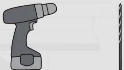
natural_image
Illustration of a handheld electric drill and a pair of tweezers (no text or symbols)9/64" Drill BitDrill
© 2024 Hunter Fan Company
7130 Goodlett Farms Pkwy, Suite 400
MemphisTN38016
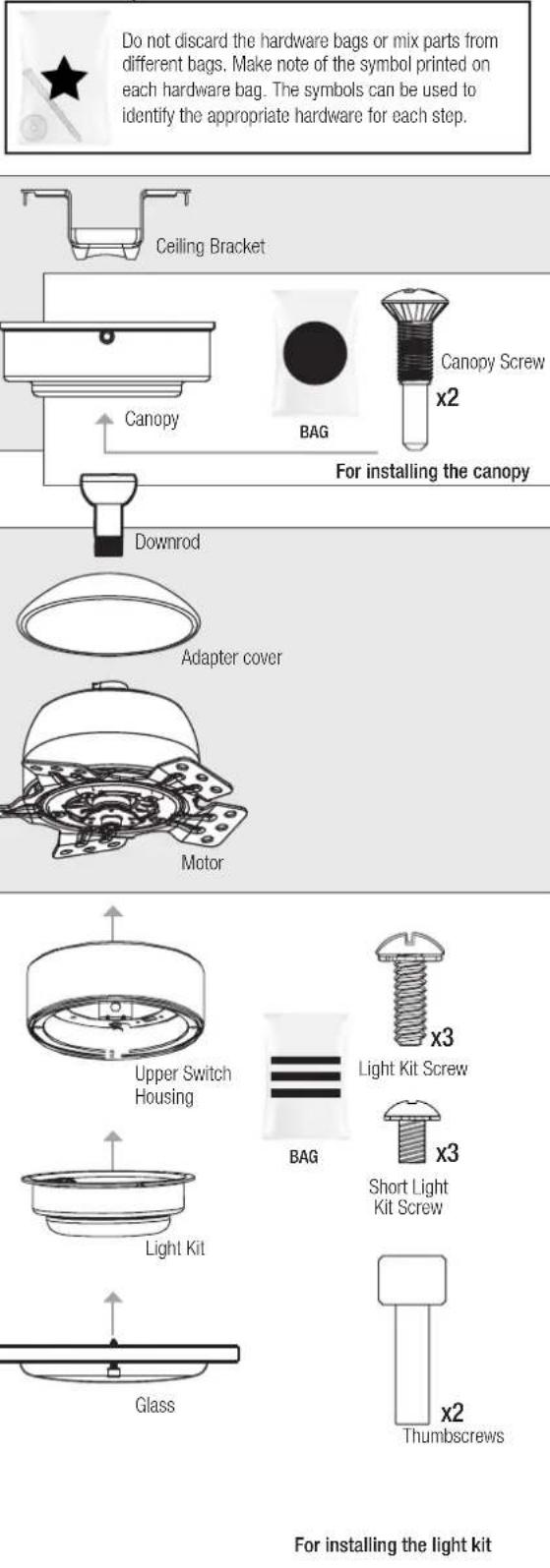
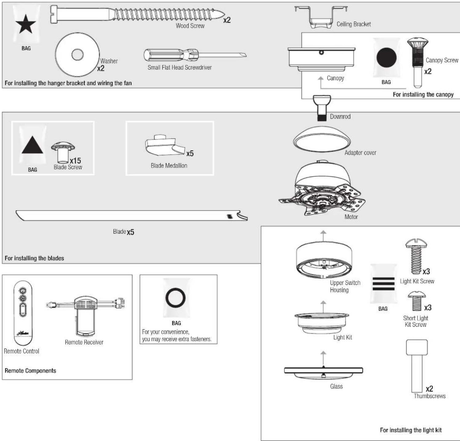
Here is what comes in your box:
We recommend that you pull everything out of the box and lay it out. We have grouped the drawn components below with the hardware you'll need for those parts. The screws below are drawn to scale to make it easier to identify what piece of hardware is needed to install each component.
Hunter Pro Tip:
Note:
Fan style may vary.

Find a part that is missing or damaged?
Don't take it back to the store. Let us make it right. Visit us at HunterFan.com or call us at 1.888.830.1326.
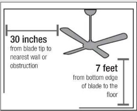
Choosing the Right Installation Location
You probably bought this fan with a location in mind. Let's check below to make sure it is a good fit.
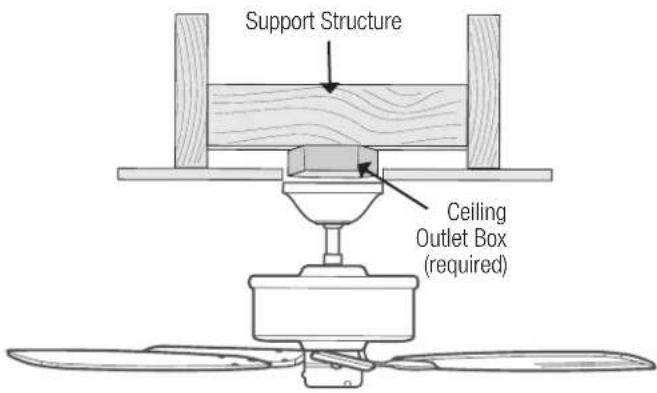
Check the room dimensions: Check the outlet box:
For ceilings over 10 feet, purchase a DC wire extension kit and downrod online.
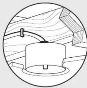
natural_image
Simple line drawing of a mechanical component with a curved pipe and base, set against a wooden background (no text or symbols)You must be able to secure the fan to building structure or fan-rated outlet box.
Checking the Ceiling Angle:
Standard Mounting
If you have a flat ceiling:
Hang your fan by a standard downrod. Some fans come with a shorter downrod for a Low Profile installation.

If you have an angled or vaulted ceiling:
- You will need a longer downrod. (sold separately at HunterFan.com)
- If your ceiling angle is greater than 34^ , you will also need an Angled Mounting Kit. (Sold separately at HunterFan.com)
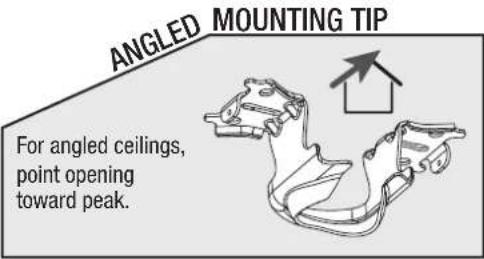
Angled Mounting
A little more information on Angled Mounting:
For optimum performance and appearance, a longer downrod should be used with your Hunter ceiling fan when installing on high or angled ceiling. If your ceiling is angled greater than 34° you will also need an Angled Mounting Kit. Longer downrods and the Angled Mounting Kit are sold separately at HunterFan.com.
Hunter Pro Tip:
Determining if you need an Angled Mounting Kit: Fold on the dotted line. Place against edge against the wall. Slide towards the ceiling. If the guide touches the wall but not the ceiling, you need an angled mounting kit.

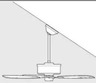
natural_image
Line drawing of a three-blade fan with a vertical support and diagonal line above (no text or symbols)


Installing the Ceiling Bracket
You have two options for installation. Pick which one works best for your location. Remove any existing bracket prior to installation. Only use the provided Hunter ceiling bracket that came in your fan's box.

Do this first!
Option 1: Machine Screws
Use machine screws (provided with outlet box) and washers when securing to existing ceiling fan-rated outlet box. Make sure it is securely installed and is acceptable for fan support of 31.8 kg (70 lbs) or less.
Box Outlet Mount
Option 2: Wood Screws
Use wood screws and washers (included) when securing to support structure with approved electrical outlet box. Drill 9/64" pilot holes in support structure to aid in securing ceiling bracket with hardware found in the ★ hardware bag.
Building Structure Mount
Hunter Pro Tip:
The machine screws are the ones that came with your outlet box.
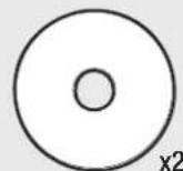
Washer

BAG

natural_image
Line drawing of a screw with threaded shaft and pointed tip (no text or symbols)Wood Screw
Wiring the Fan

Connect wiring from ceiling to terminal block (on side of canopy mount) and tighten using flathead screwdriver (included).
WARNING

- To avoid possible electrical shock, before installing your fan, disconnect the power by turning off the circuit breakers to the outlet box associated with the wall switch location.
- All wiring must be in accordance with national and local electrical codes ANSI/NFPA 70. If you are unfamiliar with wiring or in doubt, consult a qualified electrician.
- The ceiling fan must be grounded. If the ground wire for the installation site is not present, immediately STOP installation and consult a qualified electrician.
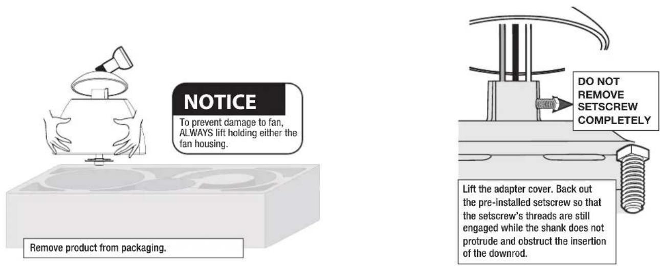
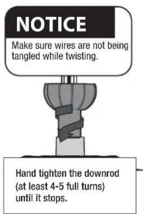
Installing the Downrod
Follow below if you are using the downrod that came pre-assembled in your box. Need to install a longer or shorter downrod? Check out the guide at the end of this manual.
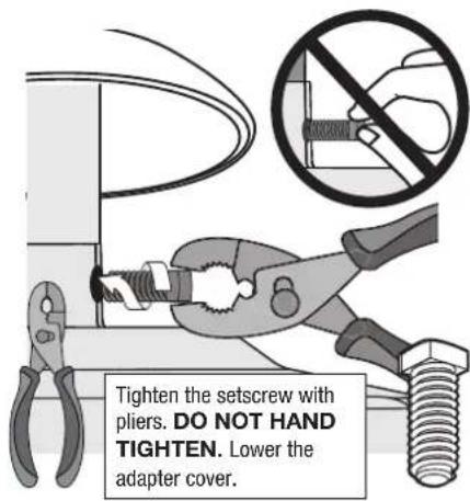
WARNING
FAN FALL HAZARD
To prevent SERIOUS INJURY or DEATH:
• ALWAYS tighten setscrew with pliers.
• DO NOT hand tighten setscrew.
- CHECK the setscrew is tight using pliers each time you change fan direction.
- Pin must be reinserted to secure downrod assembly
Hanging the Fan

Making Connections for the Receiver and the Fan

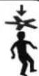
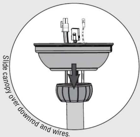
Installing the Canopy
Note:
Fan style may vary.
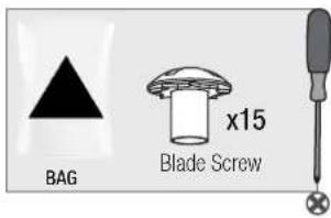
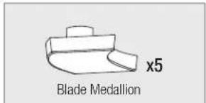
Installing the Blades:
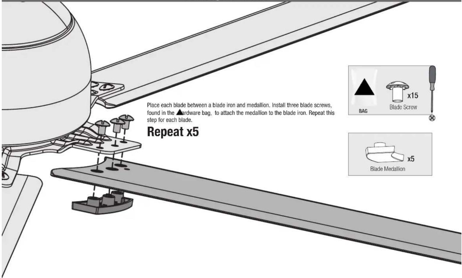
Note:
Fan style may vary.
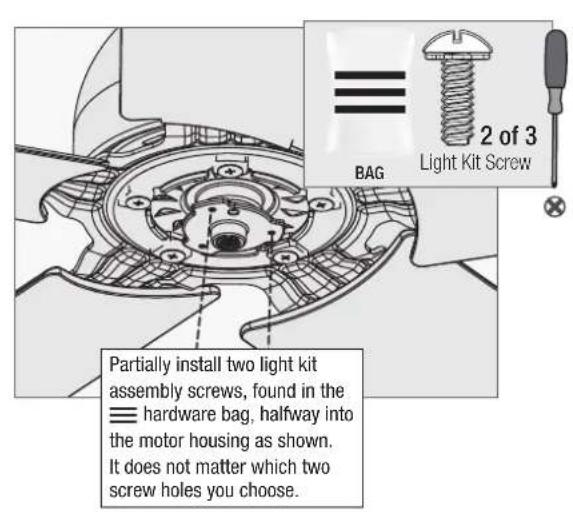
Assembling the Light Kit

natural_image
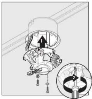
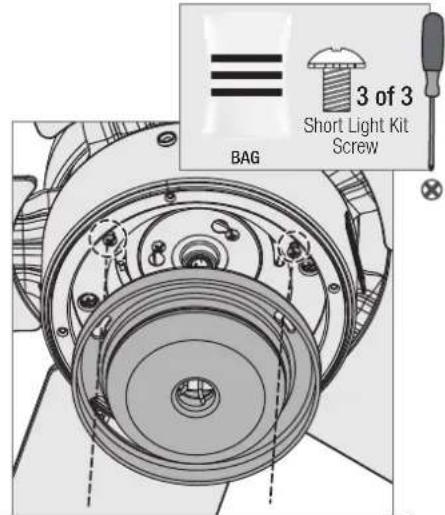
Technical diagram of a mechanical component with circular features and internal components, shown in two views (no text or labels)Partially install two of the light kit screws found in bag. It does not matter which two screw holes you choose. Connect the plugs from the upper switch housing and the LED assembly. Connect the white wires together. Connect the blue and black wires together.

natural_image
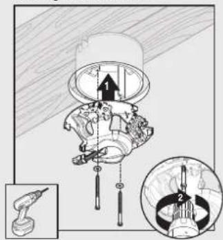
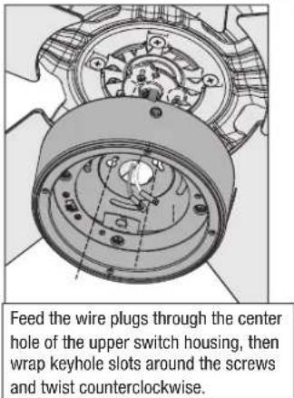
Technical line drawing of a mechanical assembly with concentric gears and mounting holes (no text or symbols)Align the keyhole slots in the light kit housing with the two screws. Make sure all the wires from the fan and the light kit are snug inside the center of the light kit, not pinched in between the upper switch housing and the light kit or hanging out of the sides.
Note:
Fan style may vary.
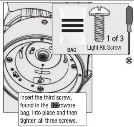
Turn the light kit counterclockwise until the light kit screws are firmly situated in the narrow end of the keyhole slots. Install the third screw and tighten all three screws securely.
WARNING
FAN FALL HAZARD
Make sure all screws are tight to secure the light fixture.
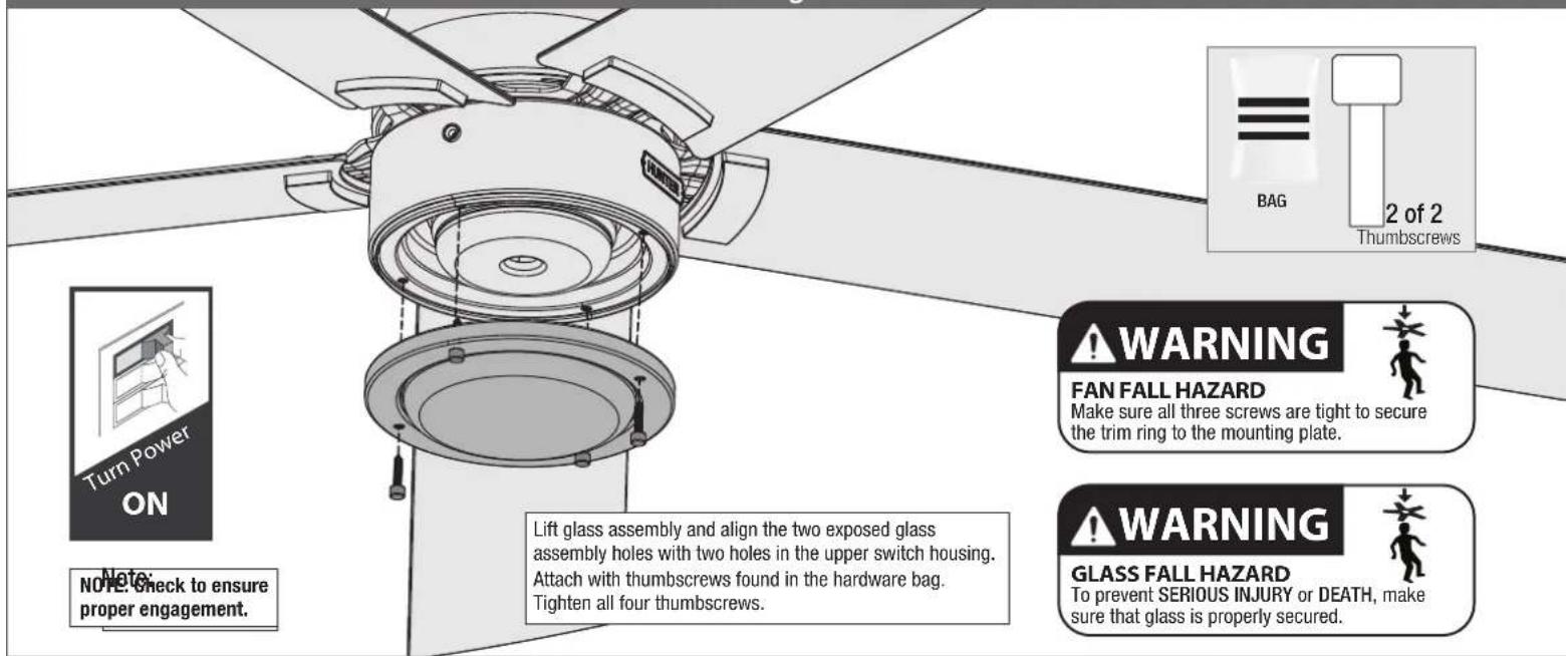
Installing the Glass
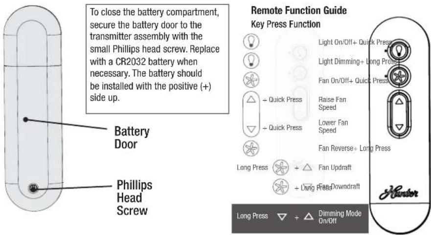
Preparing the Remote
The remote control is already paired for use. For your convenience, a remote function card is packed in with your remote.

WARNING INGESTION HAZARD: This product contains a button cell or coin battery.
WARNING
- INGESTION HAZARD: This product contains a button cell or coin battery.
• DEATH or serious injury can occur if ingested. -
A swallowed button cell or coin battery can cause Internal Chemical Burns in as little as 2 hours.
-
KEEP new and used batteries OUT OF REACH OF CHILDREN
- Seek immediate medical attention if a battery is suspected to be swallowed or inserted inside any part of the body.

NOTICE
• Always purchase the correct size and grade of battery most suitable for the intended use.
- Clean the battery contacts and also those of the device prior to battery installation.
- Remove and immediately recycle or dispose of used batteries according to local regulations and keep away from children. Do NOT dispose of batteries in household trash or incinerate.
• Even used batteries may cause severe injury or death.
- Call a local poison control center for treatment information.
• Compatible battery type is CR2032, 3 V
- Ensure the batteries are installed correctly with regard to polarity (+ and -).
- Do not mix old and new batteries, different brands or types of batteries, such as alkaline, carbon-zinc, or rechargeable batteries
- Non-rechargeable batteries are not to be recharged. Exhausted batteries are to be removed from the product.
- Do not force discharge, recharge, disassemble, heat above (manufacturer's specified temperature rating) or incinerate. Doing so may result in injury due to venting, leakage or explosion resulting in chemical burns.
- Remove and immediately recycle or dispose of batteries from equipment not used for an extended period of time according to local regulations.
- Always completely secure the battery compartment. If the battery compartment does not close securely, stop using the product, remove the batteries, and keep them away from children.
Reversing the Fan
natural_image
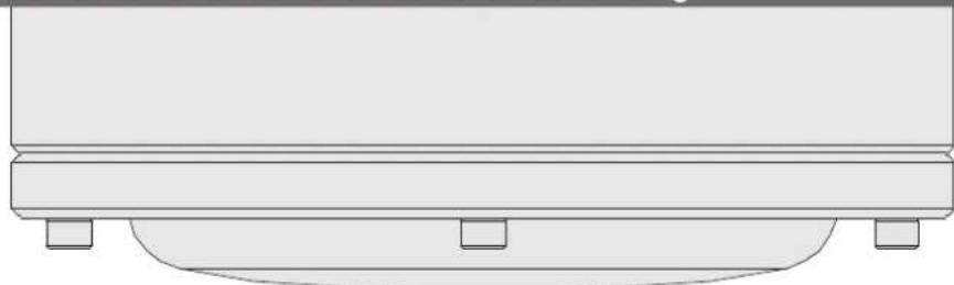
Simple line drawing of a rectangular object with a base and two small square feet at the bottom (no text or symbols)Ceiling fans work in two directions: downdraft (counterclockwise rotation) and updraft (clockwise rotation). To change the direction of air flow, turn the fan off and let it come to a complete stop. Use the remote control to change direction. Restart the fan.
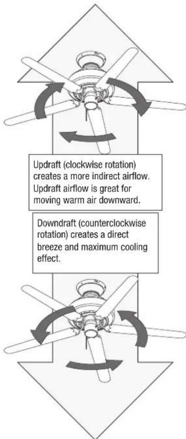
flowchart
graph TD
    A["Updraft (clockwise rotation)"] --> B["Updraft airflow is great for moving warm air downward."]
    C["Downdraft (counterclockwise rotation)"] --> D["Downdraft airflow is more indirect airflow."]
    E["Downdraft"] --> F["Downdraft airflow creates a direct breeze and maximum cooling effect."]
Note:
Fan style may vary.
Limited Lifetime Warranty
Hunter Fan Company grants this limited warranty to the original purchaser of this Hunter ceiling fan. This document can be found at www.HunterFan.com. Thank you for choosing Hunter!
How Can Warranty Service Be Obtained?
Proof of purchase is required when requesting warranty service. The original purchaser must present a sales receipt or other document that establishes proof of purchase. Hunter, at its sole discretion, may accept a gift receipt. To obtain service, contact Hunter Fan Company online or by phone.
www.HunterFan.com/Support/Contact-Us/1-888-830-1326
Please do not ship your fan or any fan parts to Hunter. Delivery will be refused.
What Does This Warranty Cover?
Motor — Limited Lifetime Warranty
If any part of your ceiling fan motor fails during your ownership of the fan due to a defect in material or workmanship, as determined solely by Hunter, Hunter will provide you with a replacement fan free of charge.* The foregoing limited warranty applies only to the motor itself and does not apply to electronic controls – such as remote control transmitters, remote control receivers, or capacitors – used in conjunction with the motor. Such electronic control items are included in the Three-year limited warranty below.
Other — Three-Year Limited Warranty
Except as otherwise indicated throughout this warranty, if any part of your Hunter ceiling fan fails at any time within three years of the date of purchase due to a defect in material or workmanship, as determined solely by Hunter, Hunter will provide a replacement part free of charge.*
* If no replacement product/part can be provided for your fan, we will provide a comparable or superior replacement product/part at the sole discretion of Hunter.
What Does This Warranty NOT Cover?
Labor Excluded. This warranty does not cover any costs or fees associated with the labor (including electrician's fees) required to install, remove, or replace a fan or any fan parts. There is no warranty for light bulbs; remote control batteries; fans purchased or installed outside the United States; fans owned by someone other than the original purchaser; fans for which proof of purchase has not been established; fans purchased from an unauthorized dealer; ordinary wear and tear; minor cosmetic blemishes; refurbished fans; and fans that are damaged due to any of the following: improper installation, misuse, abuse, improper care, failure to follow Hunter instructions, accidental damage caused by the fan owner or related parties, modifications to the fan, improper or incorrectly performed maintenance or repair, improper voltage supply or power surge, use of improper parts or accessories, failure to provide maintenance to the fan, or acts of God (e.g. flood).
ORIGINAL PURCHASER'S SOLE AND EXCLUSIVE REMEDY FOR A CLAIM OF ANY KIND WITH RESPECT TO THIS PRODUCT SHALL BE THE REMEDIES SET FORTH HEREIN. HUNTER FAN COMPANY IS NOT RESPONSIBLE FOR CONSEQUENTIAL OR INCIDENTAL DAMAGES, DUE TO PRODUCT FAILURE, WHETHER ARISING OUT OF BREACH OF WARRANTY, BREACH OF CONTRACT, OR OTHERWISE. Some States do not allow the exclusion or limitation of incidental or consequential damages, so the above limitation or exclusion may not apply to you.
ANY IMPLIED WARRANTIES OF MERCHANTABILITY OR FITNESS FOR A PARTICULAR PURPOSE APPLICABLE TO THIS PRODUCT ARE LIMITED IN DURATION TO THE PERIOD OF COVERAGE OF THE APPLICABLE LIMITED WARRANTIES SET FORTH ABOVE. Some States do not allow limitations on how long an implied warranty lasts, so the above limitation may not apply to you.
How Does State Law Affect Warranty Coverage?
This warranty gives you specific legal rights. You may also have other rights which vary from state to state.
Troubleshooting
Fan Doesn't Work
• Make sure power switch is on.
- Check the circuit breaker to ensure the power is turned on.
• Make sure the blades spin freely.
- Turn off power from the circuit breaker, then loosen the canopy and check all the connections according to the wiring diagram.
Excessive Wobbling
- Make sure the blades are properly installed on the blade iron posts.
- Turn the power off, support the fan carefully, and check that the hanger ball is properly seated.
Remote Control of Fan is Erratic
- Make sure the battery is installed correctly.
• Install a fresh battery.
Remote Only Works Close to Fan
- Change battery.
Noisy Operation
• Make sure the blades are properly installed.
- Check to see if any of the blades are cracked. If so, replace all of the blades.
Multiple Remote Issues
- If you have multiple remotes or multiple remote-controlled fans installed on the same circuit breaker and you are experiencing interference or faulty operation of your remote controls, please go to www.HunterFan.com/FAQs and click "How do I properly install multiple remote-controlled fans?" for information on how to correct this issue.
Fan moves backwards and forwards when turned on.
- This is normal start-up procedure for DC motor fans. The partial movement during start-up is the result of the DC motor aligning the internal magnetic poles for proper motor operation. This design saves electricity and allows the fan to operate much quieter than standard AC motor fans.
Hunter Pro Tip:
Cleaning the Fan
Use soft brushes or cloths to prevent scratching. Cleaning products may damage the finishes.
Downrod
If you need a different downrod length follow these steps:

Remove ball (A), inner sleeve (B) and downrod (C) from fan body and wiring harnesses.
WARNING
FAN FALL HAZARD
To prevent SERIOUS INJURY or DEATH:
• ALWAYS tighten setscrew with pliers.
• DO NOT hand tighten setscrew.
- CHECK the setscrew is tight using pliers each time you change fan direction.
- Pin must be reinserted to secure downrod assembly
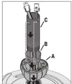
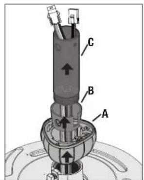
Route wiring harnesses from the fan through the accessory downrod (C). Slide inner sleeve (B) and ball (A) over downrod. Make sure to align the holes for the sleeve (B) and downrod (C).

Reinstall small metal pin (B) and ground screw (C). Slide ball up (C).
natural_image
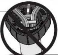
Cross-sectional diagram of a mechanical component with internal channels and a central shaft (no text or labels)NOTICE
Make sure all wiring from the wiring harnesses are on one side of the downrod pin to avoid wire entanglement when engaging the dowrod. Do not have wiring on the same side as the grounding screw to avoid damage to the wiring.
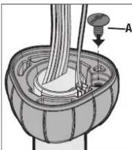
natural_image
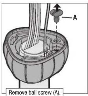
Technical diagram of a mechanical assembly with labeled component A (no text or symbols present)Reinstall ball screw (A).
For ceilings over 10 feet, purchase a DC wire extension kit and downrod online.
- Erling
- Installation Manual
- We are here to help!
- READ and SAVE These Instructions
- WARNING
- Caution
- Here are the tools you'll need to complete your installation:
- OPTIONAL
- Here is what comes in your box:
- Choosing the Right Installation Location
- Check the room dimensions: Check the outlet box:
- Checking the Ceiling Angle:
- If you have an angled or vaulted ceiling:
- Angled Mounting
- A little more information on Angled Mounting:
- Hunter Pro Tip:
- Installing the Ceiling Bracket
- Option 1: Machine Screws
- Option 2: Wood Screws
- Wiring the Fan
- Installing the Downrod
- FAN FALL HAZARD
- Hanging the Fan
- Installing the Blades:
- Preparing the Remote
- NOTICE
- Reversing the Fan
- Limited Lifetime Warranty
- How Can Warranty Service Be Obtained?
- What Does This Warranty Cover?
- Motor — Limited Lifetime Warranty
- Other — Three-Year Limited Warranty
- What Does This Warranty NOT Cover?
- How Does State Law Affect Warranty Coverage?
- Troubleshooting
- Fan Doesn't Work
- Excessive Wobbling
- Remote Control of Fan is Erratic
- Remote Only Works Close to Fan
- Noisy Operation
- Multiple Remote Issues
- Fan moves backwards and forwards when turned on.
- Downrod
- If you need a different downrod length follow these steps:
Brand : HUNTER
Model : Erling
Category : Fan