
HC30WW - Chest Freezer Summit - Free user manual and instructions
Find the device manual for free HC30WW Summit in PDF.

| Product Type | Chest Freezer |
| Brand | Summit |
| Model | HC30WW |
| Color | White |
| Total Capacity | 3.0 cu. ft. |
| Electrical Requirements | 115 V / 60 Hz |
| Amperage | 0.9 A |
| Energy Consumption | ~250 kWh/year |
| Defrost Type | Manual |
| Temperature Control | Adjustable thermostat |
| Interior Light | Yes |
| Locking Lid | Yes, with key |
| Door Swing | Lift-up lid |
| Refrigerant | R600a |
| Climate Class | N/ST |
| Noise Level | < 40 dB |
| Dimensions (W x D x H) | 30" x 19.5" x 28" |
| Net Weight | 55 lbs |
| Warranty | 1 year parts and labor |
| Removable Basket | Yes, includes one storage basket |
Frequently Asked Questions - HC30WW Summit
User questions about HC30WW Summit
0 question about this device. Answer the ones you know or ask your own.
Ask a new question about this device
Download the instructions for your Chest Freezer in PDF format for free! Find your manual HC30WW - Summit and take your electronic device back in hand. On this page are published all the documents necessary for the use of your device. HC30WW by Summit.
USER MANUAL HC30WW Summit
SAFETY INFORMATION ......2
USING THE HOOD
Controls 4
CARE AND CLEANING
Filter 5
Surfaces 6
Lights....6
INSTALLATION INSTRUCTIONS .....7
TROUBLESHOOTING TIPS .....17
LIMITED WARRANTY....18
CUSTOMER SUPPORT......26
SUMMIT
OWNER'S MANUAL
& INSTALLATION
INSTRUCTIONS
MODELS:
HC20BB HC24BB
HC20SS HC24WW
HC20WW HC30WW
HC30BB
Write the model and serial numbers here:
Model # ____
Serial # ____
You can find them on a label on the inside of the hood.
READ AND SAVE THESE INSTRUCTIONS
IMPORTANT SAFETY INFORMATION READ ALL INSTRUCTIONS BEFORE USING
⚠ WARNING TO REDUCE THE RISK OF FIRE, ELECTRIC SHOCK, OR INJURY TO PERSONS, OBSERVE THE FOLLOWING:
A. Use this unit only in the manner intended by the manufacturer. If you have questions, contact the manufacturer.
B. Before servicing or cleaning the unit, switch the power off at the service panel and lock the service disconnecting means to prevent power from being switched on accidentally. When the service disconnecting means cannot be locked, securely fasten a prominent warning device, such as a tag, to the service panel.
C. Do not use this unit with any solid-state speed control device.
D. This unit must be grounded.
⚠ WARNING TO REDUCE THE RISK OF A RANGE TOP GREASE FIRE:
A. Never leave surface units unattended at high settings. Boilovers cause smoking and greasy spillovers that may ignite. Heat oil slowly on medium settings.
B. Always turn the hood ON when cooking at high heat or when flambéing food (i.e., Crepes, Suzette, Cherries Jubilee, Peppercorn Beef Flambé).
C. Clean ventilating fans frequently. Grease should not be allowed to accumulate on the fan or filter.
D. Use proper pan size. Always use cookware appropriate for the size of the surface element.
⚠ WARNING TO REDUCE THE RISK OF INJURY TO PERSONS IN THE EVENT OF A RANGE TOP GREASE FIRE, OBSERVE THE FOLLOWING\*:
A. SMOTHER FLAMES with a close-fitting lid, cookie sheet, or metal tray, then turn off the burner. BE CAREFUL TO PREVENT BURNS. If the flames do not go out immediately, EVACUATE AND CALL THE FIRE DEPARTMENT.
B. NEVER PICK UP A FLAMING PAN—You may be burned.
C. DO NOT USE WATER, including wet dishcloths or towels—a violent steam explosion will result.
D. Use an extinguisher ONLY if:
1. You know you have a Class ABC extinguisher, and you already know how to operate it.
2. The fire is small and contained in the area where it started.
3. The fire department is being called.
4. You can fight the fire with your back to an exit.
*Based on "Kitchen Fire Safety" published by NFPA.
▲CAUTION FOR GENERAL VENTILATING USE ONLY. DO NOT USE TO EXHAUST HAZARDOUS OR EXPLOSIVE MATERIALS AND VAPORS
IMPORTANT SAFETY INFORMATION READ ALL INSTRUCTIONS BEFORE USING
REMOTE ENABLE EQUIPMENT (on some models)
This device complies with part 15 of the FCC Rules. Operation is subject to the following two conditions: (1) This device may not cause harmful interference, and (2) this device must accept any interference received, including interference that may cause undesired operation.
The wireless communication equipment installed on this hood has been tested and found to comply with the limits for a Class B digital device, pursuant to part 15 of the FCC Rules. These limits are designed to:
(a) provide reasonable protection against harmful interference in a residential installation. This equipment generates, uses, and can radiate radio frequency energy and, if not installed and used in accordance with the instructions, may cause harmful interference to radio communications. However, there is no guarantee that interference will not occur in a particular installation. If this equipment does cause harmful interference to radio or television reception, which can be determined by turning the equipment off and on, the user is encouraged to try to correct the interference by one or more of the following measures:
■ Reorient or relocate the receiving antenna.
■ Increase the separation between the equipment and receiver.
- Plug the equipment into an outlet on a circuit different from that to which the receiver is connected.
■ Consult the dealer or an experienced radio/TV technician for help.
(b) accept any interference received, including interference that may cause undesired operation of the device.
Note that any changes or modifications to the wireless communication device installed on this oven that are not expressly approved by the manufacturer could void the user's authority to operate the equipment.
How to Remove Protective Shipping Film and Packaging Tape
Carefully grasp a corner of the protective shipping film with your fingers and slowly peel it from the appliance surface. Do not use any sharp items to remove the film. Remove all the film before using the appliance for the first time.
To assure no damage is done to the finish of the product, the safest way to remove the adhesive from packaging tape on new appliances is an application of a household liquid dishwashing detergent. Apply with a soft cloth and allow to soak.
NOTE: The adhesive must be removed from all parts.
READ AND SAVE THESE INSTRUCTIONS
Controls
On Some Models
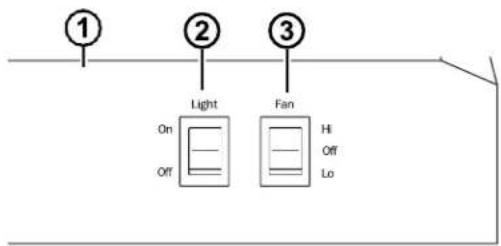
- Rangehood Control Panel: The control panel is located on the front of the canopy.
-
Light Switch: The light switch toggles between the lightbulb On and Off.
-
Fan Power Switch: The power switch toggles between fan settings Hi, Lo, and Off.
Filter
Be sure the circuit breaker is off, and all surfaces are cool before cleaning or servicing any part of the vent hood.
Charcoal Filter
For this model, the air needs to be recirculated through a disposable charcoal filter that helps remove smoke and odors.
NOTE: DO NOT rinse or put the charcoal filter in an automatic dishwasher.
The charcoal filter cannot be cleaned. It must be replaced. It is recommended that the charcoal filter be replaced every 6-12 months or if it is noticeably dirty or discolored.
To inquire about purchasing replacement charcoal filters or to find the location of a dealer near you, please call us at (718) 893-3900.
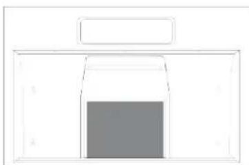
natural_image
Simple line drawing of a rectangular box with a central square (no text or symbols)A charcoal filter is included with this model.
To install:
- Slip the back edge of the filter into the retaining slot.
- Rotate the filter block pin to fix the filters in place.
To remove the filter, complete the above process in reverse.
Surfaces
Stainless Steel Surfaces (on some models)
Do not use a steel wool pad; it will scratch the surface.
Use warm sudsy water or a stainless steel cleaner or polish to clean the stainless steel surface. Always wipe the surface in the direction of the brush line. Follow the cleaner instructions for cleaning the stainless steel surface.
Use only a liquid cleanser free of grit and rub in the direction of the brush lines with a damp soft sponge.
To inquire about purchasing stainless steel appliance cleaner or polish, or to find the location of a dealer nearest you, please call us at 800-932-4267.
Painted Surfaces (on some models)
Do not use steel wool pads or other abrasive cleaners; they will scratch the surface.
Clean grease-laden surfaces of the hood frequently. To clean the hood surface, use a hot, damp cloth with a mild detergent suitable for painted surfaces. About one tablespoon of ammonia may be added to the water. Use a clean, hot, damp cloth to remove soap. Dry with a dry, clean cloth.
NOTE: When cleaning, take care not to come in contact with filters and other surfaces.
CAUTION
When cleaning the hood surfaces,
be certain that you do not touch the light with moist hands or cloth. A warm or hot light may break if touched with a moist surface. Always let the light cool completely before cleaning around it.
Lights
CAUTION
Allow lights to cool before touching.
On Some Models
- Before attempting to replace the lights, make sure that the light switch is turned off.
- Remove the lightbulb's cover.
- Unscrew the lightbulb counterclockwise and pull it out to remove the lightbulb.
- Replace the lightbulb with the same type of lightbulb (standard incandescent), making sure the socket is properly inserted into the housing of the lightbulb holder.
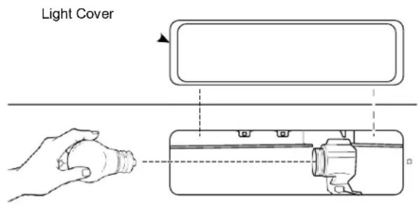
NOTE: A lightbulb is NOT included with this unit.
Installation Instructions
Under the Cabinet (UTC) Hoods
If you have questions, call Summit at 1-718-893-3900 or visit our website at: www.summitappliance.com/support
BEFORE YOU BEGIN
Read these instructions completely and carefully.
- IMPORTANT — Save these instructions for local inspector's use.
- IMPORTANT — Observe all governing codes and ordinances.
- Note to Installer – Be sure to leave these instructions with the Customer.
- Note to Customer – Keep these instructions for future reference.
- Skill level – Installation of this vent hood requires basic mechanical and electrical skills.
- Proper installation is the responsibility of the installer.
- Product failure due to improper installation is not covered under the Warranty.
FOR YOUR SAFETY
⚠ WARNING
Before beginning the installation, switch power off at service panel and lock the service disconnecting means to prevent power from being switched on accidentally. When the service disconnecting means cannot be locked, securely fasten a prominent warning device, such as a tag, to the service panel.
CAUTION
To reduce risk of fire and to properly exhaust air, be sure to duct air outside. Do not vent exhaust air into spaces within walls or ceilings or into attics, crawl spaces or garages.
WARNING
TO REDUCE THE RISK OF FIRE, ELECTRIC SHOCK, OR INJURY TO PERSONS, OBSERVE THE FOLLOWING:
A. Installation work and electrical wiring must be done by a qualified person(s) in accordance with all applicable codes and standards, including fire-rated construction.
B. Sufficient air is needed for proper combustion and exhausting of gases through the flue (chimney) of fuel-burning equipment to prevent back drafting. Follow the heating equipment manufacturer's guidelines and safety standards such as those published by the National Fire Protection Association (NFPA), the American Society for Heating, Refrigeration and Air Conditioning Engineers (ASHRAE), and the local code authorities.
C. When cutting or drilling into wall or ceiling, do not damage electrical wiring and other hidden utilities.
D. Ducted fans must always be vented to the outdoors.
⚠ WARNING
TO REDUCE THE RISK OF FIRE, USE ONLY METAL DUCT WORK.
⚠ WARNING
Disconnect all electrical power at the main circuit breaker or fuse box before installing.
DUCTWORK REQUIREMENTS
⚠ WARNING
TO REDUCE THE RISK OF FIRE, USE ONLY METAL DUCTWORK.
NOTE: Read the ductwork sections only if you do not have existing ductwork. If you have existing ductwork, skip to the "Damage" section, and proceed.
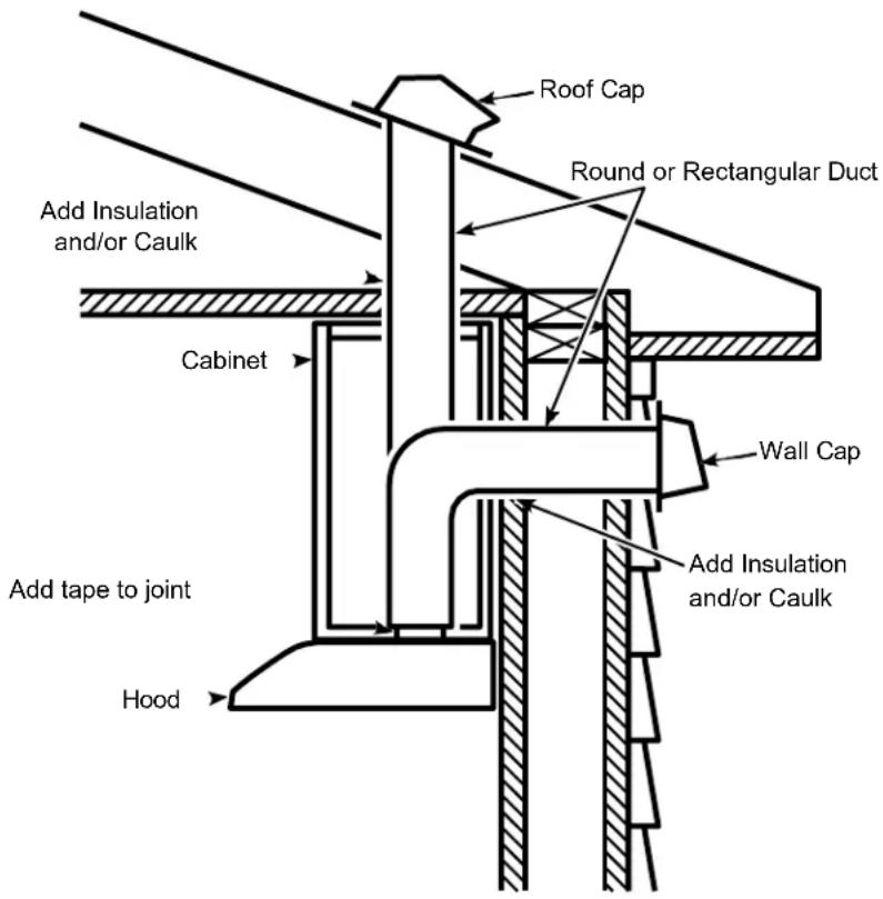
The venting system must exhaust to the outside.
This hood can be vented vertically through upper cabinets or horizontally through an outside wall. Ductwork is not included.
Exhaust connection
This hood is designed to be vented vertically using a 7" round duct or a 3 14 " x 10" rectangular duct or horizontally using a 3 14 " x 10" rectangular duct. Do not use less than a 7" diameter duct.
Duct length
The ducting from this fan to the outside of the building has a strong effect on the air flow, noise, and energy use of the fan. Use the shortest, straightest duct routing possible for best performance, and avoid installing the fan with smaller ducts than recommended. Insulation around the ducts can reduce energy loss and inhibit mold growth. Fans installed with existing ducts may not achieve their rated air flow.
INSULATION AND/OR CAULK AROUND THE DUCTS
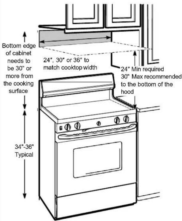
PRODUCT DIMENSIONS


NOTES:
- The width of the hood can be greater than the width of the range or cooktop, but it may not be smaller.
• Installation height should be measured from the cooking surface to the lowest part of the hood. This hood must be installed onto a cabinet. It can be vented to the outdoors, or it can be installed for recirculating operation.
MOUNTING SPACE
PLAN THE INSTALLATION
CAUTION
To reduce risk of fire and to
properly exhaust air, be sure to duct the air outside – Do not vent exhaust air into spaces within walls or ceilings or into attics, crawl spaces, or garages.
PARTS SUPPLIED FOR INSTALLATION
• 1 Hardware Package
• 1 Literature Package
• 1 Vented Mode Deflector Part
PARTS NEEDED FOR INSTALLATION
• 1 Strain Relief
• Power Supply Cable
- 1 Wall or Roof Cap (for external venting only)
- All Metal Ductwork (for external venting only)
NOTE: This range hood can be installed as either ducted or recirculation. In a ducted application, this range hood can be vented through the wall or ceiling. When installed for recirculation, the range hood vents out the front of the hood.
NOTE: Before making any cuts or holes for installation, determine which venting method will be used and carefully calculate all measurements.
TOOLS AND MATERIALS REQUIRED
(NOT INCLUDED)

Pencil and tape measure

Safety glasses
Spirit level
Wire cutter/stripper

Electric drill, #2 Phillips, flat head, and 932 " drill bit

UL listed wire nuts
Torx 10, 15, 20
driver
Strain relief for junction box
Aluminized Duct tape
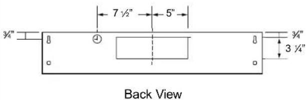
INSTALLATION DIMENSIONS

REMOVE THE PACKAGING
CAUTION
Wear gloves to protect against
sharp edges.
- Remove the hardware bag, literature package and other boxed parts.
- Remove and properly discard the protective plastic wrapping and other packaging materials.
ADVANCE PLANNING
Vented Install Planning
- This hood is designed to be vented vertically using a 7" round duct or a 3 14 " x 10" rectangular duct or horizontally using a 3 14 " x 10" rectangular duct.
- Use metal ductwork only.
- Determine the exact location of the vent hood.
-
Plan the route for venting exhaust to the outdoors. To maximize the ventilation performance of the vent system:
-
Minimize the duct run length and number of transitions and elbows.
- Maintain a constant duct size.
- Seal all joints with duct tape to prevent any leaks.
- Do not use any type of flexible ducting.
• Install a wall cap or roof cap at the exterior opening. Purchase the wall or roof cap and any transition and length of duct needed in advance.
- When applicable, install any makeup (replacement) air system in accordance with local building code requirements.
Recirculation Install Planning
This hood may be installed in recirculation mode and is shipped in this configuration. The charcoal filter is necessary for recirculation installation.
This part may need to be ordered separately depending on model.
Power Supply Planning
The location of the power supply connection is called out in the Prepare for Electrical and Venting section on page 15.
POWER SUPPLY
IMPORTANT – (please read carefully)
⚠ WARNING
FOR PERSONAL SAFETY, THIS APPLIANCE MUST BE PROPERLY GROUNDED.
Remove house fuse or open circuit breaker before beginning installation.
Do not use an extension cord or adapter plug with this appliance. Follow National Electrical Codes or prevailing local codes and ordinances.
Electrical supply
These vent hoods must be supplied with 120V, 60Hz, and connected to an individual, properly grounded branch circuit, and protected by a 15 or 20 amp circuit breaker or time delay fuse.
- Wiring must be 2 wire with ground.
- If the electrical supply does not meet the above requirements, call a licensed electrician before proceeding.
- Route house wiring as close to the installation location as possible in the ceiling or wall.
- Connect the wiring to the house wiring in accordance with local codes.
Grounding instructions
The grounding conductor must be connected to a ground metal, permanent wiring system, or an equipment-grounding terminal or lead on the hood.
WARNING
The improper connection of the
equipment-grounding conductor can result in a risk of electric shock. Check with a qualified electrician or service representative if you are in doubt whether the appliance is properly grounded.
1 SELECT VENT OPTION THAT YOUR INSTALLATION WILL REQUIRE (A-D)
A Outside top exhaust
(Vertical duct—3¼" x 10" Rectangular)

natural_image
Simple line drawing of a mechanical component with an upward arrow indicating force or motion (no text or symbols)B Outside top exhaust (Vertical duct—7" Round)

natural_image
Simple line drawing of a mechanical component with a central circular feature and an upward arrow (no text or symbols)C Outside rear exhaust (Horizontal duct—3 14 " x 10" Rectangular)

natural_image
Simple line drawing of a rectangular metal tray with a downward arrow indicating direction (no text or symbols)D Recirculating (Unit is shipped from the factory in this configuration)
natural_image
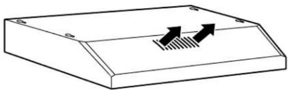
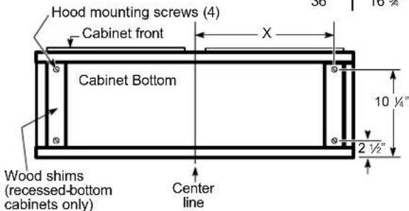
Simple line drawing of a rectangular electronic component with two upward-pointing arrows and a hatched base (no text or symbols)2 PREPARING MOUNTING
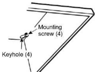
A To install to the bottom of cabinet
Use the diagram or hood as a template and mark the locations on the cabinet for the keyhole screws.
Drive the 4 (F) screws partway into the bottom of the cabinet (or wood shims).
| Cabinet | X |
| 24" | 10 34" |
| 30" | 13 34" |
| 36" | 16 34" |
3 PREPARE FOR ELECTRICAL AND VENTING
Select the vent option that your installation will require and proceed to that section:
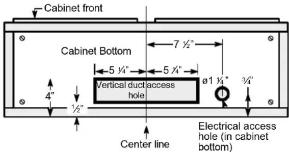
A Outside top exhaust
(Vertical duct-3 1/4" x 10" Rectangular)
- Use the diagram as a template and mark the locations on the cabinet for ductwork and electrical wiring.
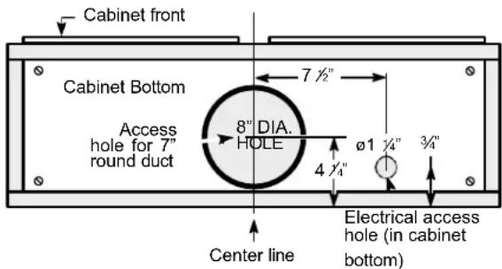
B Outside top exhaust
(Vertical duct-7" Round)
- Use the diagram as a template and mark the locations on the cabinet for ductwork and electrical wiring.
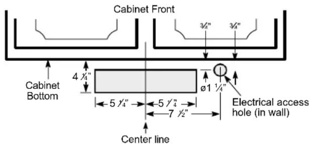
C Outside rear exhaust
(Horizontal duct-3 1/4" x 10" Rectangular)
- Use the diagram as a template and mark the locations on the cabinet for ductwork and electrical wiring.
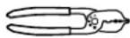
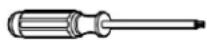
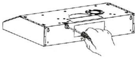
4 REMOVE ELECTRICAL KNOCKOUTS
Use a flat blade screwdriver, remove the appropriate electrical knockout from the back or the top of the hood.
natural_image
Hand using a tool to adjust or install a mechanical component (no text or symbols visible)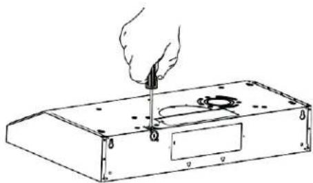
natural_image
Line drawing of a hand using a tool to press or install electronic components on a rectangular base (no text or symbols)5 REMOVE JUNCTION BOX
Remove junction box from inside the hood. Set the junction box and mounting screws aside.

1" = 2.5 cm ; 1' = 0.3 m
6 REMOVE DUCT KNOCKOUT(S) FOR VENTED INSTALLATION
Determine which ducting option to use. Using a flat blade screwdriver, remove the appropriate duct knockout(s) from the top or back of the hood.
3 ¼" x 10" Rectangular vertical discharge. Remove top rectangular duct knockout only.
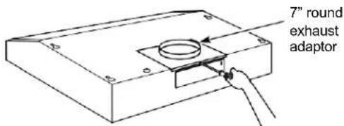
7" Round vertical discharge. Remove semi-circular duct knockout and top rectangular duct knockout.

3 1/4" x 10" Rectangular horizontal discharge. Remove rear rectangular duct knockout only.
NOTE: If the hood is to be installed in a recirculation, non-vented ductless manner, do not remove any venting knockouts.
NOTE: For an ENERGY STAR® model, unit must be vented mode to be considered ENERGY STAR® certified.
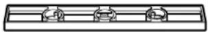
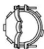
7 ATTACH DAMPER/DUCT CONNECTOR
Attach damper/duct connector over knockout opening with two or four (D) screws. Make sure damper pivot is nearest to top/back edge of hood. Remove any packaging tape to allow damper to move freely.

Rectangular Ducting
Round Ducting
8 FOR VENTED INSTALLATIONS
On Some Models:
Install with vented mode deflector part.

natural_image
Diagram of a mechanical device with arrows indicating motion or force direction, no text or symbols presentOn Some Models:
Install vented mode deflector part.

natural_image
Simple line drawing of a rectangular container with a central circular object and a hanging handle, no text or symbols present.9 FEED-IN WIRES
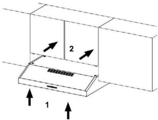
Lift the hood into position and feed the house wiring through the wiring knockout.
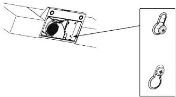
10 MOUNT THE UTC
Place the hood onto the partially installed screws using the keyholes and slide the hood back into position.
natural_image
Technical line drawing of a mechanical component with two inset views showing a circular opening and a hanging hook (no text or symbols)11 SECURE HOOD
Tighten the mounting screws. Be sure the screw heads are in the narrow neck of the keyhole slot.
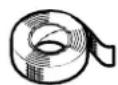
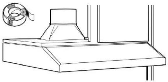
12 CONNECT DUCTWORK TO HOOD (Ducted installations only)
Connect ducting to hood. Use duct tape to make joints secure and airtight.
natural_image
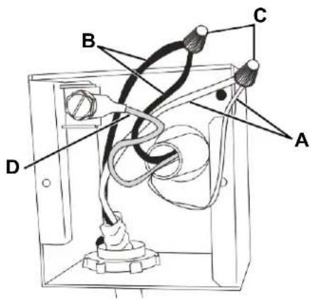
Line drawing of a kitchen chimney with a coiled cable attached (no text or symbols)13 ELECTRICAL CONNECTIONS
-
Connect the Power Supply Cable to the range hood. Attach the white lead of the power supply to the white lead of the range hood (A) with a wire nut (C). Attach the black lead of the power supply to the black lead of the range hood (B) with a wire nut (C). Connect the green (D) ground wire under the green grounding screw.
-
Replace the junction box cover.
14 FINISH THE INSTALLATION
On Some Models:
- For recirculation: Install the charcoal filter.

natural_image
Simple line drawing of a rectangular container with a lid and side markers (no text or symbols)- For ducted installation: Install the grease filters.

natural_image
Simple line drawing of a rectangular container with a central circular pattern and a top handle (no text or symbols)On Some Models:
- For recirculation: Place the charcoal filter (not included) in place and mount using 2 screws. Replace the grease filters.

natural_image
Technical line drawing of a fan assembly with internal components and mounting holes (no text or labels)- For vented installation: Install the grease filters.

natural_image
Two side panels of a textured fabric or panel with circular ends, no visible text or symbols.Troubleshooting tips ... Before you call for service
You can solve many common problems easily, saving you the cost of a possible service call. Try the suggestions below to see if you can solve the problem before calling for service.
| Problem | Possible Cause | What To Do |
| Fan/Light does not operate when either button is pressed | A house fuse may be blown, or a circuit breaker tripped. | Replace the fuse or reset the circuit breaker. |
| Fan does not operate when fan Lo, Med, Hi buttons are pressed | The blower connector is loose or not plugged into its mating connector. | Disconnect power to the unit. Remove the filters and look up at the blower. If the blower connector plug is loose or you see the connector dangling, the installer failed to plug it in securely. See the mini manual for the plug location and how to plug in the connector. |
| Loud or abnormal airflow noise | Wrong duct size during installation. | Using smaller duct pipe will cause reduced venting. Minimize the duct run length and number of transitions and elbows. GE service technicians cannot correct this issue if installed improperly. |
| Fan fails to circulate air or moves air slower than normal and/or fan is making loud or abnormal airflow noise | Obstructions in duct work. | Make sure nothing is blocking the vent. Make sure your wall or roof cap has a blade or door. |
| Damper blade on wall or roof cap may not be open. | Make sure damper swings freely. Damper blades may flip over and will not fully open when this happens. Adjust to original position. | |
| Metal grease filter and charcoal filter (if present) may be dirty. | Clean the metal grease filter and replace charcoal filter (if present). See Care and Cleaning of the Vent Hood. | |
| Insufficient makeup (replacement) air | Sufficient makeup (replacement) air is required for exhausting appliances to operate at an optimal level. Check with local building codes, which may require or strongly advise the use of makeup air. | |
| The hood controls are not operating correctly | Control logic confused. | Disconnect power to the hood by resetting the circuit breaker. Wait 30 seconds to allow controls to reset. |
| Early light failure | Light wattage is too high. | Replace with correct wattage (40W recommended) |
| Fan continually cycles off and on | The motor is probably overheating and turning itself off. This can be harmful to the motor. Filter may be excessively soiled. | Clean the metal grease filter and replace charcoal filter (if present). See Care and Cleaning of the Vent Hood. |
If you have checked the information above and find that you still need help with your appliance, call our Customer Service facility at 800-932-4267 between 9:00 AM and 5:00 PM ET or visit https://www.summitappliance.com/support any time. We will do our best to answer your questions.
Within the 48 contiguous United States, for one year from the date of purchase, when this appliance is operated and maintained according to instructions attached to or furnished with the product, the warrantor will pay for factory-specified parts and repair labor to correct defects in materials or workmanship. Service must be provided by a designated service company. Outside the 48 states, all parts are warranted for one year from manufacturing defects. Plastic parts, shelves, and cabinets are warranted to be manufactured to commercially acceptable standards and are not covered from damage during handling or breakage.
ITEMS WARRANTOR WILL NOT PAY FOR:
- Service calls to correct the installation of your appliance, to instruct you how to use your appliance, to replace or repair fuses, or to correct wiring or plumbing.
- Service calls to repair or replace appliance light bulbs or broken glass shelves. Consumable parts (such as filters) are excluded from warranty coverage.
- Damage resulting from accident, alteration, misuse, abuse, fire, flood, acts of God, improper installation, installation not in accordance with electrical or plumbing codes, or use of products not approved by the warrantor.
- Replacement parts or repair labor costs for units operated outside the United States.
- Repairs to parts or systems resulting from unauthorized modifications made to the appliance.
- The removal and reinstallation of your appliance if it is installed in an inaccessible location or is not installed in accordance with published installation instructions.
DISCLAIMER OF IMPLIED WARRANTIES; LIMITATION OF REMEDIES
THE CUSTOMER'S SOLE AND EXCLUSIVE REMEDY UNDER THIS LIMITED WARRANTY SHALL BE PRODUCT REPAIR AS PROVIDED HEREIN. IMPLIED WARRANTIES, INCLUDING WARRANTIES OF MERCHANTABILITY OR FITNESS FOR A PARTICULAR PURPOSE, ARE LIMITED TO ONE YEAR. WARRANTOR SHALL NOT BE LIABLE FOR INCIDENTAL OR CONSEQUENTIAL DAMAGES. SOME STATES DO NOT ALLOW THE EXCLUSION OR LIMITATION OF INCIDENTAL OR CONSEQUENTIAL DAMAGES, OR LIMITATIONS ON THE DURATION OF IMPLIED WARRANTIES OF MERCHANTABILITY OR FITNESS, SO THESE EXCLUSIONS OR LIMITATIONS MAY NOT APPLY TO YOU. THIS WARRANTY GIVES YOU SPECIFIC LEGAL RIGHTS AND YOU MAY ALSO HAVE OTHER RIGHTS, WHICH VARY FROM STATE TO STATE.

WARNING: This product can expose you to chemicals including Nickel (Metallic) which is known to the State of California to cause cancer.
For more information go to www.P65Warnings.ca.gov
Note: Nickel is a component in all stainless steel and some other metallic compositions.
SUMMIT®
An ISO 9001:2015 registered company
770 Garrison Avenue Bronx, NY 10474
TEL 718-893-3900
FAX 844-478-8799

info@summitappliance.com
www.summitappliance.com
991.0701.864_01-230413
D_00009305_00


- SUMMIT
- READ AND SAVE THESE INSTRUCTIONS
- IMPORTANT SAFETY INFORMATION READ ALL INSTRUCTIONS BEFORE USING
- ⚠ WARNING TO REDUCE THE RISK OF FIRE, ELECTRIC SHOCK, OR INJURY TO PERSONS, OBSERVE THE FOLLOWING:
- ⚠ WARNING TO REDUCE THE RISK OF A RANGE TOP GREASE FIRE:
- ⚠ WARNING TO REDUCE THE RISK OF INJURY TO PERSONS IN THE EVENT OF A RANGE TOP GREASE FIRE, OBSERVE THE FOLLOWING\*:
- ▲CAUTION FOR GENERAL VENTILATING USE ONLY. DO NOT USE TO EXHAUST HAZARDOUS OR EXPLOSIVE MATERIALS AND VAPORS
- REMOTE ENABLE EQUIPMENT (on some models)
- How to Remove Protective Shipping Film and Packaging Tape
- Controls
- On Some Models
- Filter
- Charcoal Filter
- To install:
- Surfaces
- Stainless Steel Surfaces (on some models)
- Painted Surfaces (on some models)
- CAUTION
- Lights
- Installation Instructions
- Under the Cabinet (UTC) Hoods
- BEFORE YOU BEGIN
- FOR YOUR SAFETY
- ⚠ WARNING
- WARNING
- DUCTWORK REQUIREMENTS
- Exhaust connection
- Duct length
- NOTES:
- PLAN THE INSTALLATION
- PARTS SUPPLIED FOR INSTALLATION
- PARTS NEEDED FOR INSTALLATION
- REMOVE THE PACKAGING
- ADVANCE PLANNING
- Vented Install Planning
- Recirculation Install Planning
- Power Supply Planning
- POWER SUPPLY
- IMPORTANT – (please read carefully)
- Electrical supply
- Grounding instructions
- PREPARE FOR ELECTRICAL AND VENTING
- A Outside top exhaust
- B Outside top exhaust
- C Outside rear exhaust
- REMOVE ELECTRICAL KNOCKOUTS
- REMOVE JUNCTION BOX
- REMOVE DUCT KNOCKOUT(S) FOR VENTED INSTALLATION
- ATTACH DAMPER/DUCT CONNECTOR
- FOR VENTED INSTALLATIONS
- On Some Models:
- FEED-IN WIRES
- MOUNT THE UTC
- SECURE HOOD
- CONNECT DUCTWORK TO HOOD (Ducted installations only)
- ELECTRICAL CONNECTIONS
- FINISH THE INSTALLATION
- Troubleshooting tips ... Before you call for service
- ITEMS WARRANTOR WILL NOT PAY FOR:
- DISCLAIMER OF IMPLIED WARRANTIES; LIMITATION OF REMEDIES
- SUMMIT®
Brand : Summit
Model : HC30WW
Category : Chest Freezer