
CA-HM-MIT-PSA.001 - Unspecified PIONEER - Free user manual and instructions
Find the device manual for free CA-HM-MIT-PSA.001 PIONEER in PDF.

| Product Type | Car Stereo Installation Kit |
| Brand | Pioneer (Metra 99-7013) |
| Model | CA-HM-MIT-PSA.001 |
| Compatible Vehicles | Mitsubishi Outlander 2007-2008 |
| Radio Provision Types | DIN with Pocket, ISO Mount with Pocket, Double DIN, Stacked ISO Units |
| Kit Components | Radio housing, trim plate, brackets, pocket, double DIN trim plate, labels |
| Dimensions (Approx.) | 7" x 4" x 2" (fits standard DIN slots) |
| Weight | 1.2 lbs (approx.) |
| Material | Plastic, metal brackets |
| Mounting Hardware | Screws and brackets included |
| Wiring Harness | EIA color code compatible (adapter not included) |
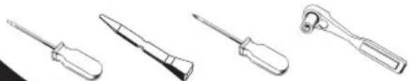
| Tools Required | Small flat blade screwdriver, Phillips screwdriver, socket set |
| Installation Difficulty | Moderate |
| Safety Features | Disconnect battery before installation; tape unused wires |
| Maintenance | Periodic check of connections; keep dry |
| Warranty | 1 year limited warranty (check manufacturer) |
Frequently Asked Questions - CA-HM-MIT-PSA.001 PIONEER
User questions about CA-HM-MIT-PSA.001 PIONEER
0 question about this device. Answer the ones you know or ask your own.
Ask a new question about this device
Download the instructions for your Unspecified in PDF format for free! Find your manual CA-HM-MIT-PSA.001 - PIONEER and take your electronic device back in hand. On this page are published all the documents necessary for the use of your device. CA-HM-MIT-PSA.001 by PIONEER.
USER MANUAL CA-HM-MIT-PSA.001 PIONEER
INSTALLATION INSTRUCTIONS FOR PART 99-7013
APPLICATIONS
Mitsubishi Outlander
2007-2008
99-7013
KIT FEATURES
• DIN Radio Provision with Pocket
• ISO Mount Radio Provision with Pocket
• Double DIN Radio Provision
- Stacked ISO Mount Units Provision
natural_image
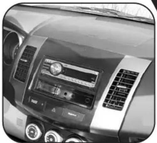
Interior view of a car dashboard with air filters and a central touchscreen display (no visible text or symbols)KIT COMPONENTS
natural_image
Technical line drawing of a 3D mechanical component with no visible text or symbols
natural_image
Technical line drawings of mechanical components labeled B, D, and E (no text or symbols on parts)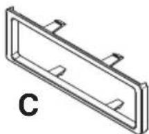
natural_image
Technical line drawing of a rectangular frame with mounting holes and a label 'C' (no text or symbols on the diagram itself)TOOLS REQUIRED:
natural_image
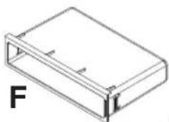
Isometric line drawing of a rectangular box with a flat top and side connectors, labeled 'F' (no text or symbols on the diagram itself)Small Flat Blade Screwdriver/ Panel Removal Tool
- Phillips Screwdriver - Socket Set
natural_image
Line drawings of four different screwdriver tools (no text or symbols)TABLE OF CONTENTS
Dash Disassembly
- Mitsubishi Outlander 2007-2008 ..... 1,2
Kit Preparation .... 3
Kit Assembly
- DIN Radio Provision with Pocket ....4
- ISO Mount Radio Provision with Pocket 5
- Double DIN/Stacked ISO Units Provision 6
Final Assembly 7
*Note:
Refer also to the instructions included with the aftermarket radio.
MITSUBISHI OUTLANDER 2007-2008
1 Disconnect the negative battery terminal to prevent an accidental short circuit.
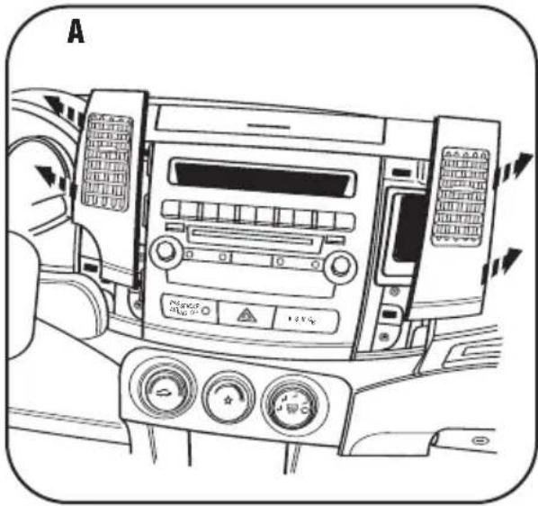
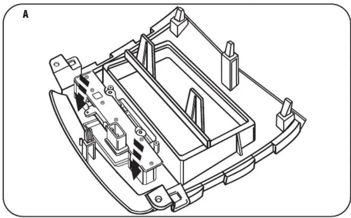
2 Unclip and remove the vents from the left and right side of the factory radio panel. (Figure A)
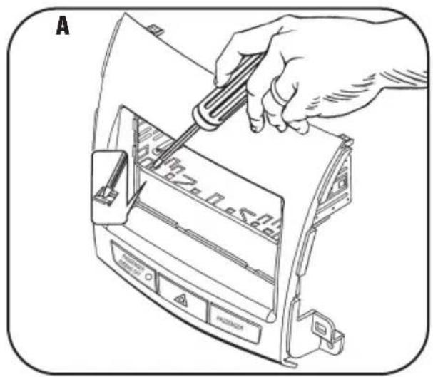
3 Remove (2) Phillips screws securing the radio trim panel then unclip and remove the panel. (Figure B)
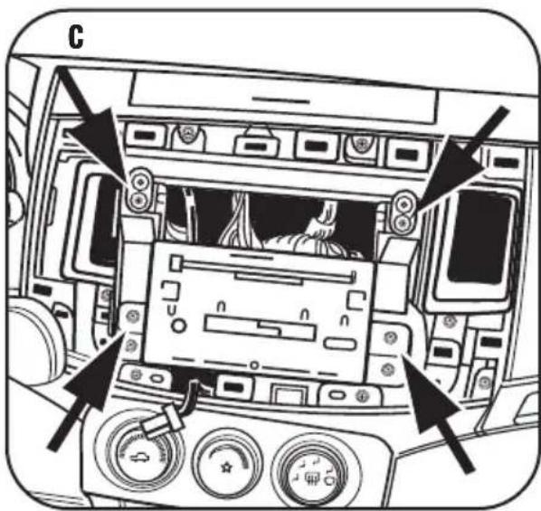
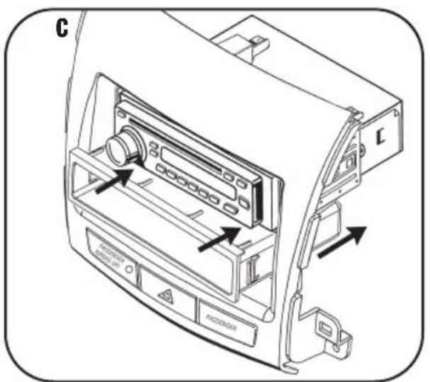
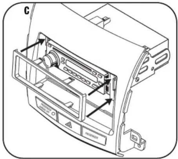
4 Remove (4) Phillips screws securing the radio chassis. Unplug and remove the chassis. (Figure C)
Continued on page 2.
natural_image
Interior view of a car dashboard with air conditioners, controls, and directional arrows (no text or symbols)
MITSUBISHI OUTLANDER 2007-2008
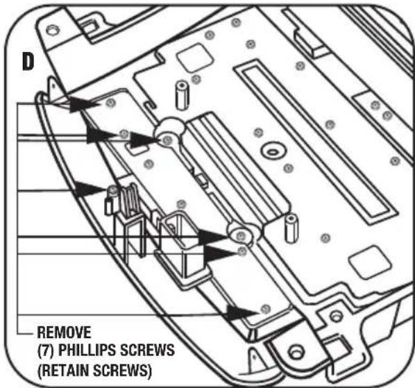
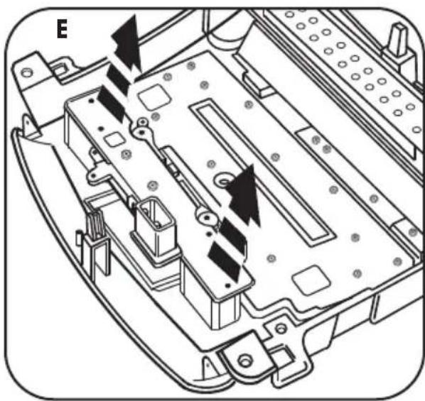
5 Remove (7) Phillips screws securing the hazard switch assembly to the back of the factory radio trim panel. Unplug the ribbon cable from the hazard switch assembly and remove assembly from panel from rear. (Retain the screws and switch assembly to be reused during kit preparation) (Figure D,E)
6 Remove the labels from the front of the radio trim panel at each side of the hazard switch by pushing them out from behind the panel. (Retain the labels to be reused during kit preparation) (Figure F)
Continued to kit preparation.

MITSUBISHI OUTLANDER 2007-2008
5 Secure the hazard switch panel into the radio housing using the factory hardware removed previously and apply labels from the front of the factory radio trim panel to front of the Metra radio panel. (Figure A,B)
Continue to kit assembly.
natural_image
Technical line drawing of a mechanical assembly with no visible text or symbols
DIN RADIO PROVISION WITH POCKET
*Note: Refer also to the instructions included with the aftermarket radio.
1 Slide the DIN cage into the Radio Housing and secure by bending the metal locking tabs outward. (Figure A)
2 Slide the aftermarket radio into the cage until it snaps into place. (Figure B)
3 Snap the pocket into the radio housing. (Figure C)
Continue to final assembly.
natural_image
Line drawing of a hand using a screwdriver to adjust or install electronic components on a device (no text or symbols visible)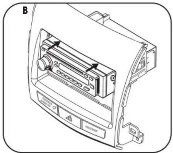
ISO MOUNT RADIO PROVISION WITH POCKET
*Note: Refer also to the instructions included with the aftermarket radio.
1 Mount the ISO Brackets to the aftermarket radio using the screws supplied with the radio. (Figure A)
2 Slide the radio into the Radio Housing until it snaps into place. (Figure B)
3 Snap the Trim Plate onto the front of the Radio Housing. (Figure C)
4 Snap the pocket into the Radio Housing. (Figure D)
Continue to final assembly.

natural_image
Illustration of a hand using a screwdriver to adjust or install an electronic device component (no text or symbols visible)

DOUBLE DIN/STACKED ISO UNITS PROVISION
*Note: Refer also to the instructions included with the aftermarket radio.
1 Cut and remove the center bar from the Radio Housing. (Figure A)
2 Snap the Double DIN Brackets to the inside edge of the Radio Housing. (Figure B)
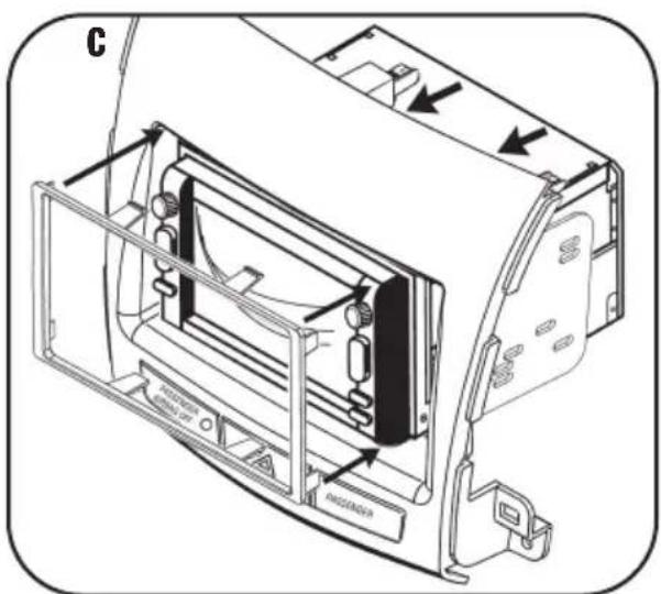
3 Slide the Double DIN or stacked ISO unit(s) into the bracket/radio housing assembly and secure the Double DIN or stacked ISO unit(s) to the assembly using the screws supplied with the unit(s). (Figure C)
4 Snap the Double DIN Trim Plate onto the front of the Radio Housing. (Figure C)
Continue to final assembly.


FINAL ASSEMBLY
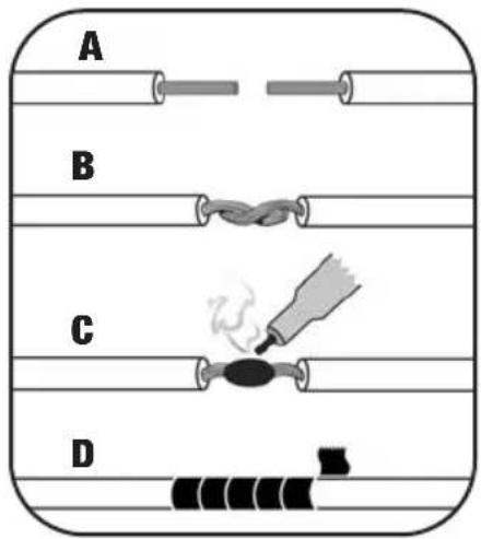
(A) Strip wire ends back 1/2"
B) Twist ends together
C) Solder
D) Tape
1 Locate the factory wiring harness in the dash. Metra recommends using the proper mating adapter and making connections as shown. (Isolate and individually tape off the ends of any unused wires to prevent electrical short circuit.)
2 Re-connect the negative battery terminal and test the unit for proper operation.
3 Reassemble radio and dash assemblies in reverse order of disassembly.
FINAL WIRING CONNECTIONS
Make wiring connections using the EIA color code chart shown below and the instructions included with the head unit. Metra recommends making connections as shown below; Strip, Splice, Solder, Tape. Isolate and individually tape off ends of any unused wires to prevent electrical short circuit.
METRA / EIA WIRING CODE
| 12V Ignition / Acc......Red | Right Front (+)......Gray |
| 12V Batt / Memory......Yellow | Right Front (-)......Gray/ Black |
| Ground......Black* | Left Front (+)......White |
| Power Antenna......Blue | Left Front (-)......White / Black |
| Amp Turn-On......Blue / White | Right Rear (+)......Violet |
| Amp Ground......Black / White | Right Rear (-)......Violet / Black |
| Illumination......Orange | Left Rear (+)......Green |
| Dimmer......Orange / White | Left Rear (-)......Green / Black |
*NOTE: When a Black wire is not present, ground radio to vehicle chassis. All colors may not be present on all leads due to manufacturer's specifications.
NOTES
NOTES
99-7013 INSTRUCTIONS
- INSTALLATION INSTRUCTIONS FOR PART 99-7013
- APPLICATIONS
- Mitsubishi Outlander
- 2007-2008
- 99-7013
- KIT FEATURES
- KIT COMPONENTS
- TABLE OF CONTENTS
- Dash Disassembly
- Kit Assembly
- MITSUBISHI OUTLANDER 2007-2008
- DIN RADIO PROVISION WITH POCKET
- ISO MOUNT RADIO PROVISION WITH POCKET
- DOUBLE DIN/STACKED ISO UNITS PROVISION
- FINAL ASSEMBLY
- FINAL WIRING CONNECTIONS
- NOTES
Brand : PIONEER
Model : CA-HM-MIT-PSA.001
Category : Unspecified