
Cable Cubby F55 - Mobile device accessory Extron - Free user manual and instructions
Find the device manual for free Cable Cubby F55 Extron in PDF.

| Product Type | Lift-up cable access enclosure for AV connectivity, remote control, and power |
| Brand | Extron |
| Model | Cable Cubby F55 |
| Cut-out Dimensions (Width x Depth) | 10.50 x 6.00 inches (267 x 152 mm) |
| Estimated Weight | 2.5 lbs (1.1 kg) |
| Material | Aluminum and steel with plastic components |
| Mounting Type | Furniture mountable, flush with table surface |
| Compatible Modules | Flex55 and EU modules (half-, full-, and double-size), including AC and USB power modules |
| Included Accessories | 2 Flex55 Adapter Modules, 4 #10-32 screws, 4 zip ties, 2 cable grommet plates, 2 pry tools, 1 Tweeker |
| Optional Accessories | ZipClip 100, 200, or 400 mounting devices |
| Lid Operation | Lifts up to expose connectivity interface at ergonomic angle; nearly flush when closed |
| Cable Pass-through | Supported via cable grommet plates; allow at least 36 inches (914 mm) cable loop per cable |
| Installation Requirements | Must be installed by licensed craftspeople; comply with local building and electrical codes; safety glasses required |
| Safety Warnings | Flanged edges are sharp; handle with care; use appropriate personal protective equipment |
| Maintenance | Clean with a soft, dry cloth; avoid abrasive cleaners |
| Spare Parts and Repairability | Modules are replaceable; removal of bridge supports for double-size modules is irreversible |
| Compliance | Designed in accordance with Extron safety and regulatory guidelines; check local accessibility requirements (e.g., ADA) |
| Operating Temperature | Not specified; typical room temperature |
| Color | Black (standard) |
| Warranty | Extron standard warranty; contact manufacturer for details |
Frequently Asked Questions - Cable Cubby F55 Extron
User questions about Cable Cubby F55 Extron
0 question about this device. Answer the ones you know or ask your own.
Ask a new question about this device
Download the instructions for your Mobile device accessory in PDF format for free! Find your manual Cable Cubby F55 - Extron and take your electronic device back in hand. On this page are published all the documents necessary for the use of your device. Cable Cubby F55 by Extron.
USER MANUAL Cable Cubby F55 Extron
Cable Cubby F55 • Installation Guide
This guide provides instructions for an experienced technician to install and connect the Extron Cable Cubby F55.
The Cable Cubby F55 is a lift-up cable access, furniture mountable enclosure for AV connectivity, remote control, and power. The lid lifts up to expose the connectivity interface at a comfortable and ergonomic angle. When closed, the Cable Cubby is nearly flush with the table surface.
Planning the Installation
Check with local and state regulations before starting the installation
- Ensure that the planned installation complies with national and local building and electrical codes.
- Ensure that the planned installation complies with the Americans with Disabilities Act or other accessibility requirements.

natural_image
Illustration of a wall-mounted electrical socket with internal components and a small device, placed on a wooden surface (no text or symbols)Check All Parts and Equipment
- Ensure that all parts are present in each kit.
- Ensure that necessary tools and equipment are available for the installation.
Kit contents

natural_image
3D technical illustration of a cable cubby F55 device with internal compartments and mounting base (no text or symbols on the diagram itself)
Flex55 Adapter Module (2)

10-32 Screws (4)

Zip Ties (4)

Cable Grommet Plate (2)

Pry Tool (2)

Tweeker
Optional Accessories

ZipClip 100

ZipClip 200

ZipClip 400
Figure 1. Cable Cubby F55 Kit Contents
Cable Cubby F55 • Installation Guide (Continued)
Application diagram
The application diagram below shows a power, data, and video wiring setup from a laptop to a conference monitor.
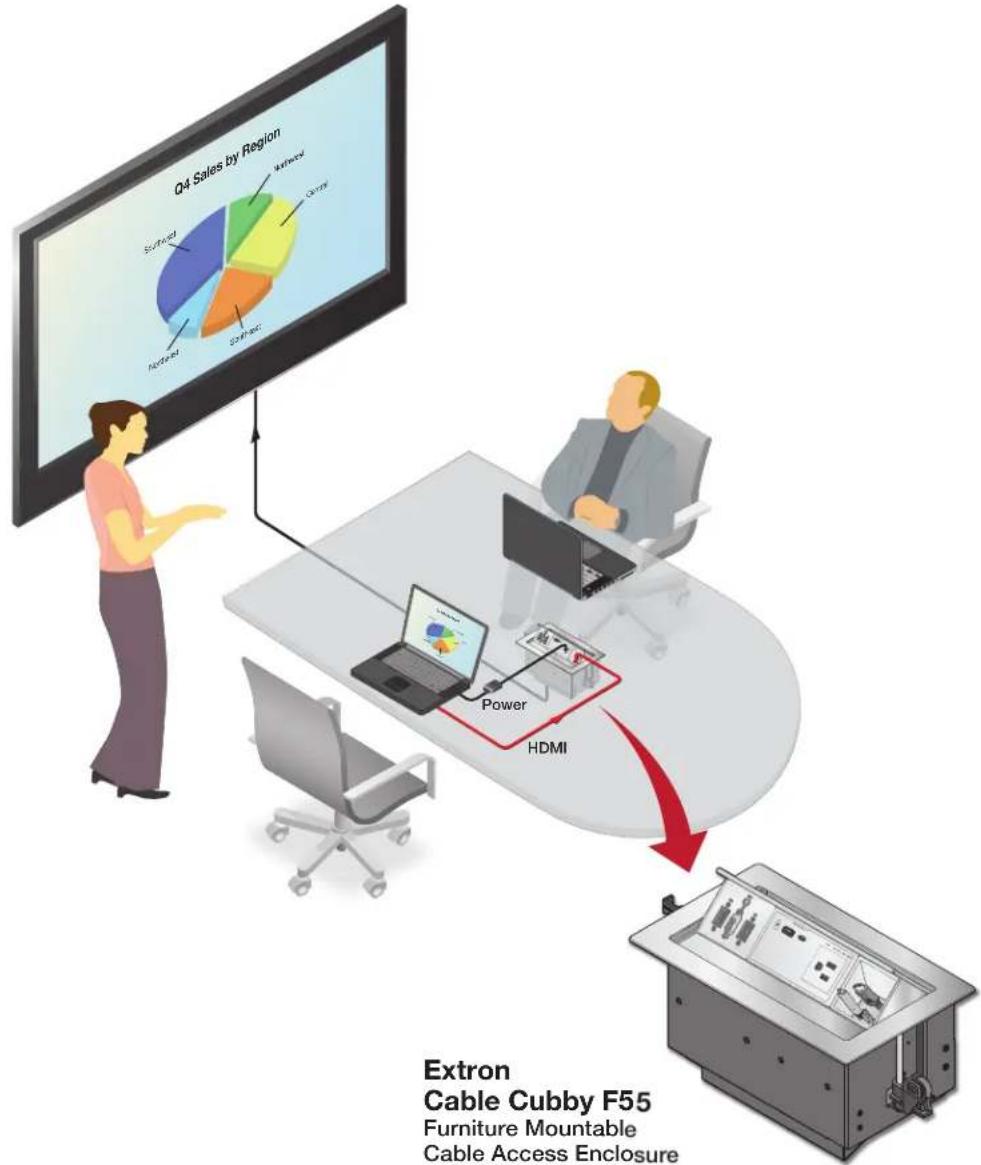
Figure 2. Application Example Using the Cable Cubby F55 Enclosure
Preparing the Table
Determine the Best Location for the Enclosure
- Ensure that the location where the Cable Cubby is to be installed is convenient for as many users as possible.
- Ensure that the edge on which the lid opens is oriented correctly.
- Ensure that there is ample space under the table for cables. Allow at least 36 inches of cable loop for each cable (see Routing and Managing Cables on page 8).
CAUTION: The flanged edges of the top of the surface enclosure are sharp. These edges are also soft and may be easily nicked or bent. Exercise caution when handling the enclosure to prevent personal injury or damage to the enclosure.
Cut a Hole in the Table
Read the following information before making a cut in the table.
CAUTION: Wear safety glasses when operating power equipment. Failure to comply can result in eye injury.
ATTENTION: The opening in the table for the Cable Cubby should be cut only by licensed and bonded craftspeople. Exercise care to prevent scarring or damaging the furniture.
- Choose one of the following methods for cutting the hole:
| Hand Router and Routing Template Jigsaw and Paper Cut-Out Template CNC Wood Router | ||||
 | 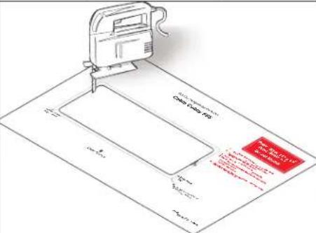 | If using a CNC wood router or other precise machinery, use the exact cut-out dimensions (see the table below). | ||
| Cut-out Dimensions | ||||
| User Access Width | Side Dimension | |||
| Cable Cubby F55 | 10.50" (267 mm) | 6.00" (152 mm) | ||
| Go to www.extron.com for routing template part numbers and instructions. | Dimensions and cut-out templates are available online at www.extron.com. | |||
- Measure and cut the hole in the surface where the enclosure will be installed.
Installing the Modules into the Cable Cubby F55 Enclosure
The Cable Cubby F55 enclosure supports Flex55 and EU modules, which can be installed in a variety of combinations. These modules can be installed either before or after the Cable Cubby F55 installation, in any slot of the enclosure. Determine where the connectivity modules and power module will be installed in the enclosure.
NOTE: For a complete and up-to-date list of compatible modules, see the product page at www.extron.com.
Figure 3 shows the process for removing the supports in order to install a double-size module, such as the Flex55 AC+USB 130 US Power Module, into the Cable Cubby F55 enclosure. Half- and full-size modules can be snapped into the enclosure without removing the supports (①).

For a double-size module installation, use pliers to carefully twist the desired support back and forth until loose, and remove.
NOTE: Removal of a bridge support is irreversible.

Extron Cable Cubby F55 Enclosure
Figure 3. Removing a Support for a Double-sized Flex55 Module Installation
② Install the cable grommet plate for cable pass-through applications.
d Snap included grommet plugs into any unused holes in the grommet plate.
C Align the adapter module with an opening in the Cable Cubby F55 frame and then snap it into place in the enclosure.

a For cable pass-through installation, insert the cables through the bottom of the Cable Cubby F55, through the Cable Cubby F55 Adapter Module, and then through the holes of the grommet plate.
b Snap the grommet plate into the Adapter Module.
Figure 4. Setting Up the Cable Grommet Plate

Figure 5. Installing Flex55 and EU Modules into the Cable Cubby F55 Enclosure
Cable Cubby F55 • Installation Guide (Continued)
Attaching an Optional ZipClip Mounting Device to the Cable Cubby F55
The ZipClip 100, 200, or 400 can be attached to the Cable Cubby F55 with the included #10-32 screws, in order to mount a power supply or other device to the enclosure. Determine which ZipClip to use, and ensure there is ample space for the device and its cables.
NOTE: All ZipClips must be mounted with horizontal orientation.

Figure 6. Mounting a ZipClip to the Cable Cubby F55 Enclosure
Mounting the Cable Cubby F55 in the Table
Step 1 — Mount the Cable Cubby Flush with the Table

Figure 7. Mounting the Cable Cubby F55 to a Table
Cable Cubby F55 • Installation Guide (Continued)
Step 2 — Under the Table, Adjust the Side Clamps on the Enclosure

Rotate the side clamp outward and ensure that the lever is down.
Slide the clamp all the way up against the bottom of the table.
Ensure the Cable Cubby is firmly seated in the table. Raise the lever to secure the Cable Cubby.
Figure 8. Adjusting and Securing the Side Clamps
Cable Cubby F55 • Installation Guide (Continued)
Routing and Managing Cables
Organize and connect cables as shown in figure 8. Use zip ties (provided) to fasten the cables to the enclosure where needed.
1 Manage the cables with the lid in the fully open position.

② For cable pass-through applications, allow at least 36 inches (914 mm) of cable loop for each cable.


③ Manage cables for fixed modules by zip-tying the cables to the bottom of the unit.
Give a generous cable loop to allow the lid to open and close without restrictions.
4 Raise and lower the lid again after cabling is installed to ensure the lid operates as desired. Provide more loop in the cabling if necessary and re-secure to the enclosure.
Figure 9. Routing and Managing the Cables
Cable Cubby F55 • Installation Guide (Continued)
Appendix
Removing Flex55 and EU Modules from the Cable Cubby F55
If the modules need to be replaced or removed from the Cable Cubby F55 enclosure, the following diagrams show the procedure for removing modules with the provided pry tools. This process applies to any compatible Flex55 and EU module.

4 Repeat steps 1 through 3 on the other side of the module.
Figure 10. Removing a Double Module
NOTE: To verify the location of the locking tabs, check the module specifications (available at www.extron.com).

Figure 11. Removing Flex55 and EU Modules
Cable Cubby F55 • Installation Guide (Continued)
Removing the Enclosure from the Table
To remove the Cable Cubby F55 enclosure from its mounting location in the table, release the side clamps as shown below:
NOTE: When the clamps cannot be loosened by hand, an Extron Tweeker or other small screwdriver may be necessary to help with leverage.

Figure 12. Removing the Cable Cubby F55 Enclosure from the Table
Installation Overview
1. Plan the installation (see page 1).
- Check with local and state regulations before starting the installation.
- Check all parts and equipment before installation.
2. Prepare the table (see page 2).
• Determine the best location for the enclosure.
- Choose a method for cutting the hole in the table.
3. Install the modules into the Cable Cubby F55 enclosure (see page 3).
- Check the modules for compatibility and installation requirements.
- Remove bridge supports if necessary to accommodate a double-sized module. Note that removal of bridge supports is irreversible.
- Cable and install half-, single- and double-size modules into the Cable Cubby F55.
4. (Optional) Attach a ZipClip mounting device to the Cable Cubby F55 (see page 5).
- If using a ZipClip, determine which model to use (100, 200, or 400). Plan and ensure there is ample space for the device and its cables.
- Attach the ZipClip to the Cable Cubby F55.
- Attach the desired power supply or other device to the ZipClip.
5. Mount the Cable Cubby F55 in the table (see page 6).
- Seat the clamps against the enclosure and in the lowest position.
- Drop the enclosure into the cut opening.
- Remove the plastic strip and film.
- Under the table, adjust the side clamps on the enclosure, and secure it to the table.
6. Route and manage the cables (see page 8).
- Organize and connect the cables. For cable pass-through applications, allow at least 36 inches (1 meter) of cable loop.
• With the lid open, allow sufficient cable loop. Use tie wraps to attach cables to the enclosure where needed. - Raise and lower the lid to ensure it operates as desired.
For information on safety guidelines, regulatory compliances, EMI/EMF compatibility, accessibility, and related topics, see the Extron Safety and Regulatory Compliance Guide on the Extron website.
© 2023 Extron Electronics — All rights reserved. www.extron.com
All trademarks mentioned are the property of their respective owners.
Worldwide Headquarters: Extron USA West, 1025 E. Ball Road, Anaheim, CA 92805, 800.633.9876
68-3527-50 Rev. A 04 23
- Cable Cubby F55 • Installation Guide
- Planning the Installation
- Check with local and state regulations before starting the installation
- Check All Parts and Equipment
- 10-32 Screws (4)
- Cable Cubby F55 • Installation Guide (Continued)
- Application diagram
- Preparing the Table
- Determine the Best Location for the Enclosure
- Cut a Hole in the Table
- Installing the Modules into the Cable Cubby F55 Enclosure
- ② Install the cable grommet plate for cable pass-through applications.
- Attaching an Optional ZipClip Mounting Device to the Cable Cubby F55
- Mounting the Cable Cubby F55 in the Table
- Routing and Managing Cables
- Appendix
- Removing Flex55 and EU Modules from the Cable Cubby F55
- Removing the Enclosure from the Table
- Installation Overview
- Plan the installation (see page 1).
- Prepare the table (see page 2).
- Install the modules into the Cable Cubby F55 enclosure (see page 3).
- (Optional) Attach a ZipClip mounting device to the Cable Cubby F55 (see page 5).
- Mount the Cable Cubby F55 in the table (see page 6).
- Route and manage the cables (see page 8).
Brand : Extron
Model : Cable Cubby F55
Category : Mobile device accessory