
XOE30W - Cap XO - Free user manual and instructions
Find the device manual for free XOE30W XO in PDF.

| Product Type | Range Hood |
| Brand | XO |
| Model | XOE30W |
| Width | 30 inches (deduced from model) |
| Rated Voltage | 120V |
| Rated Frequency | 60Hz |
| Total Power | 250W |
| Motor Power | 150W |
| Light Power | 2 x 50W Halogen bulbs |
| Amperage | 2.08 Amps |
| Number of Motors | 1 |
| Blower Speeds | 3 (Off, Low, High) |
| Light Intensity Levels | 3 (Off, Low, High) |
| Mounting Height | 26" to 32" from cooking surface |
| Ducting Options | 6" Round, 3-1/4" x 10" Rectangle (vertical/horizontal) |
| Maximum Duct Length | 100 feet (equivalent) |
| Grease Filter Cleaning | Every 2 months, washable |
| Charcoal Filter Replacement | Every 3 months, not washable |
| Light Bulb Model | XOPXOE12B (GU10, 120V, 50W Max) |
| Replacement Mesh Filter | XOPXOE3012F (for 30" model) |
| Recirculation Filter | XORFK10 (for 30" model) |
| Warranty | 1 year limited |
| Usage | Indoor, general ventilating only |
Frequently Asked Questions - XOE30W XO
User questions about XOE30W XO
0 question about this device. Answer the ones you know or ask your own.
Ask a new question about this device
Download the instructions for your Cap in PDF format for free! Find your manual XOE30W - XO and take your electronic device back in hand. On this page are published all the documents necessary for the use of your device. XOE30W by XO.
USER MANUAL XOE30W XO
natural_image
Line drawing of a front-mounted air duct box with ventilation slots and mounting brackets (no text or symbols)XOE30
XOE36
READ AND SAVE THE INSTRUCTIONS
Call our ventilation experts at 800-966-8300
XO Hood Warranty Proof of original purchase date and invoice is needed to obtain service under warranty.
What is covered Limited 1 Year Warranty.
For 1 year from the original date of purchase, we will provide, free of charge, parts and service labor in your home to repair or replace any part of the hood that fails because of a manufacturing defect.
The warranty is extended to the original purchaser for products purchased for ordinary home use in North America.
Should you require service for your XO product call a product service specialist at 800.966.8300
What is not covered Improper Installation. Service trips to the home to teach you how to use the product. Resetting circuit breakers. Damage caused after delivery.
EXPECT MORE FROM XO
When buying any XO appliance you can be confident you have purchased a high quality, innovative, and stylish product, from a company who cares about you
Dear Customer, If you follow the recommendations contained in this Instruction Manual, our appliance will give you constant high performance and will remain efficient for many years to come.
CONTENTS
WARNING & CAUTION
CHARACTERISTICS
INSTALLATION & USE
MAINTENANCE & CLEAN
Product Specification & Technical Parameters
| Rated Voltage | 120V |
| Rated Power Frequency | 60Hz |
| Light Power | 2x50W Halogen bulbs |
| Motor Power | 150W |
| Total Power | 250W |
| Motor | 1 |
| Parameters of Ducting Outlets Options | - 6" Round Vertical Duct- 3 1/4" x 10" Rectangle Vertical Duct- 3 1/4 x 10" Rectangle Horizontal Duct |
| Ampere | 2.08 Amps |
| Mounting height | 26" to 32" from cooking surface |
XO How Beautiful K itch hens B rea th
DUCT FITTINGS:
| This Hood Must Use an 6" Round Duct. It Can Transition to 3-1/4" x 10" or 3-1/4" x 12" Duct. |
Use this chart to compute maximum permissible lengths for duct runs to outdoors.
NOTE: Do not exceed maximum permissible equivalent lengths!
Maximum duct length: 100 feet for range ho-ods.
Flexible ducting:
If flexible metal ducting is used, all the equivalent feet values in the table should be doubled. The flexible metal duct should be straight and smooth and extended as much as possible.
DO NOT use flexible plastic ducting.
NOTE: Any home ventilation system, such as a ventilation hood, may interrupt the proper flow of combustion air and exhaust required by fireplaces, gas furnaces, gas water heaters and other naturally vented systems. To minimize the chance of interruption of such naturally vented systems, follow the heating equipment manufacturer's guidelines and safety standards such as those published by NFPA and ASHRAE.
| Duct Piece: | Dimensions: | Equivalent Number Length*: | Quantity Used: | Total Equivalent Length: |
| Round, straight | 1 ft. (per foot length) | |||
| 3-1/4" x 10" straight | 1 ft. (per foot length) | |||
| 90" elbow | 12 ft. | |||
| 45" elbow | 7 ft. | |||
| 3-1/4" x 10"3-1/4" x 12"90" elbow | 14 ft.10 ft. | |||
| 3-1/4" x 10"3-1/4" x 12"45" elbow | 8 ft.6 ft. | |||
| 3-1/4" x 10"3-1/4" x 12"90" elbow | 33 ft.24 ft. | |||
| 6" round to rectangular | 2 ft. | |||
| Rectangular to 8" round | 2 ft. | |||
| 3-1/4" x 10"3-1/4" x 12"6" round to rectangular transition 90" elbow | 4 ft.4 ft. | |||
| 3-1/4" x 10"3-1/4" x 12"Rectangular to 6" round transition 90" elbow | 4 ft.4 ft. | |||
| Round wall cap with dramper | 24 ft. | |||
| 3-1/4" x 10"3-1/4" x 12"Rectangular wall cap with dramper | 24 ft.18 ft. | |||
| Round roof cap | 33 ft. | |||
| *Actual length of straight duct plus duct fitting equivalent. Equivalent length of duct pieces are based on actual tests conducted by GE Evaluation Engineering and reflect requirements for good venting performance with any ventilation hood. | Total Duct Run = | |||
WARNING
TO RUDUCE THE RICK OF FIRE, ELECTRIC SHOCK OR INJURE TO PERSONS, PLEASE OBSERVE THE FOLLOWINGS:
- Installation work and electric wiring (including switch location) must be done by the qualified person(s) in accordance with local applicable codes and standards, including fire-rated construction.
- This hood may have sharp edges. Be careful to avoid cuts and abrasions during installation and cleaning.
- The hood must be placed at a minimum distance of 26" and a maximum of 32" from the cooktop for best capture of cooking impurities and a minimum distance of 28" from gas range.
- Provide sufficient air for proper combustion and exhausting of gases through the chimney of the burning equipment to prevent back drafting. Follow the heating equipment manufacturer's guideline and safety standards such as those published by the National Fire Protection Association (NFPA), and the American Society for Heating, Refrigeration and Air Conditioning Engineer (ASHRAE), and the local code authorities.
- Ducted fans must always be vented to the outdoors.
- This appliance is design to be operated by adults. Children should not be allowed to temper with the controls or play with this appliance.
- To reduce the risk of fire or electric shock, do not use this fan with any solid-state speed control device.
- When cutting or drilling into wall or ceiling, do not damage electrical wiring and other hidden utilities.
- Before servicing or cleaning unit, switch power off at service panel and lock the service disconnecting means to prevent power from being switched on accidentally. When the service disconnecting means cannot be locked, securely fasten a prominent warning device, such as a tag, to the service panel.
- Use this unit only in the manner intended by manufacturer. If you have questions, please contact the manufacturer or local agent.
- This unit must be grounded.
WARNING-TO REDUCE THE RISK OF FIRE, USE ONLY THE METAL DUCTWORK.
WARNING - TO REDUCE THE RISK OF A RANGE TOP GREASE FIRE:
- Never leave surface units unattended at high settings. Boilovers cause smoking and greasy spillovers that may ignite. Heat oils slowly on low or medium settings.
- Always turn hood ON when cooking at high heat or when cooking flaming foods (i.e. Crepes Suzette, Cherries Jubilee, and Peppercorn Beef Flambé).
- Clean ventilating fans frequently. Grease should not be allowed to accumulate on fan or filter.
- Use proper pan size. Always use cookware appropriate for the size of the surface element.
WARNING – TO REDUCE THE RISK OF INJURY TO PERSONS IN THE EVENT OF A RANGE TOP GREASE FIRE, OBSERVE THE FOLLOWING:
- SMOTHER FLAMES with a close-fitting lid, cookie sheet, or metal tray, then turn off the burner. BE CAREFUL TO PREVENT BURNS. If the flames do not go out immediately, EVACUATE AND CALL THE FIRE DEPARTMENT.
- NEVER PICK UP A FLAMING PAN – You may be burned or spread the fire.
- DO NOT USE WATER, including wet dishcloths or towels – violent steam explosion will result.
- Use an extinguisher ONLY if:
a. You know you have a Class ABC extinguisher and you already know how to operate it.
b. The fire is small and contained in the area where it started.
c. The fire department is being called.
d. You can fight the fire with your back to an exit.
Based on "Kitchen Fire Safety Tips" published by NFPA.
CAUTION
- For indoor use only.
- For general ventilating use only. Do not use to exhaust hazardous or explosive materials and vapors.
- To avoid motor bearing damage and noisy and/or unbalanced impeller, keep drywall spray, construction dust, etc., off power unit.
- Your hood motor has a thermal fuse which will automatically shut off the motor if it becomes overheated.
- The hood MUST NOT BE LESS than 26" and at a maximum of 32" above cooktop for
best capture of cooking impurities.
- This hood is not intended to be used as a shelf.
- Please read specification for further information and requirements.
NOTE: If hood is to be installed non-ducted, buy a set of (2) non-ducted filters from your local retailer and attach them to the aluminum mesh filters.
CHARACTERISTICS
Dimension

INSTALLATION & USE
NOTE: on the stainless steel hoods, carefully remove the plastic protective film from exterior of the surfaces of the hood prior to final installation.
Caution: To Reduce Risk of Fire and Electric Shock, install this range hood only with integral blowers supplied by manufacturer.
DESCRIPTION / CONNECTION
This appliance may be installed in ducted version or non-ducted version. Use proper installation template, for replacement of ductwork and electrical cutout in cabinet or wall. For a non-ducted version installation, do not cut a duct access hole.
DUCTED VERSION
The hood discharge kitchen air saturated with odor and fume passes it through the grease filters and expels it to the outside through an outlet pipe. With this version the charcoal filters are not required.
- Determine whether the hood will discharge vertically (3 1/4"×10" or 6" round) or horizontally (3 1/4"×10" only). For vertical or horizontal discharge, run ductwork between the hood location and a roof cap or wall cap. For best results, use a minimum number of transitions and elbows.

** Duct and roof cap/wall cap are not supplied.
Warning: to avoid the risk of fire, use only the metal ductwork.
NON-DUCTED VERSION
- No need of plastic or metal duct.

- Must be installed charcoal filter on the hood.
NOTE: Buy a set of (2) non-ducted filters from your local retailer and attach them to the aluminum mesh filters.
PREPARATION OF THE HOOD BEFORE INSTALLATION
- Remove the Aluminum filter from the hood.
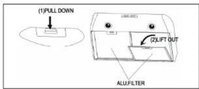
7
- Remove the bottom cover fixed in place with 3 screws.

natural_image
Line drawing of a front-loading washing machine with fan and vent (no text or symbols)- Remove the Accessory parts box from inside of the hood.

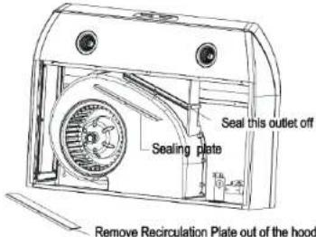
- Non ducted installation only
Remove the Recirculation Plate out of the hood and use sealing plate (supplied in the accessory box) to seal the outlet off.
- Non-ducted installation only
Attach the charcoal filter to the aluminum filter back, locking well with metal wires.
8

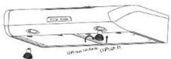
5.Ducted installation only
Tighten the Recirculation Plate and the outlet with screws.

natural_image
Technical line drawing of a mechanical device with a fan and housing (no text or symbols)- Ducted installation only
6.1 Remove 3 1/4"×10" vertical, 3 1/4"×10" horizontal, or 6" round knockout plates as appropriate for your ducting method.
6.2 Attach 3 1/4"×10" Damper/Duct connector (if using 3 1/4"×10"duct) or 6" Damper/Duct connector (if using 6" round duct) over the Knockout openings.

INSTALLATION
WARNING: To reduce the risk of electrical shock, switch power off at service panel. Lock or tag service panel to prevent power from being switched on accidentally.
-
Remove Electrical Wiring Box Cover from inside of hood and appropriate Electrical Power Cable Knockout from top or back of hood.
-
Attach house power cable to hood using appropriate clamp.
- Hold the hood in position under the cabinet. Tighten all 4 mounting screws completely to secure the hood to the cabinet.

- For ducted installation, connect ductwork to hood and use duct tape to make joints secure and air-tight. Make sure the damper/duct connector enters ductwork and that the damper opens and closes freely.
- Connect the house power cable to the range hood wiring: BLACK to BLACK, WHITE to WHITE and GREEN or BEAR WIRE to GREEN GROUD SCREW.

6.Reinstall the Bottom Cover to the hood.

natural_image
Technical line drawing of a device casing with internal components and mounting holes (no text or symbols)- Install the Halogen lamp.
- Replace the filters and turn on the power at service panel and test for proper operation.
OPERATION
The hood is operated using a rocker switch on the front panel.


Blower switch
The 3-position blower switch turns the blower ON/OFF and controls the blower speed.
Set the left side of the switch (0) turns blower on and off.
Set the middle of the switch (1) turns blower on to low speed.
Set the right side of the switch (2) turns blower to high speed.

Light switch
The 3-position blower switch turns the lights ON/OFF and controls their intensity.
Set the left side of the switch (0) turns the lights on and off.
Set the middle of the switch (1) turns the lights on to low intensity.
Set the right of the switch (2) turns the lights on to high intensity.
CAUTION- The unit is for General Ventilating Use Only. Do Not Use To Exhaust Hazardous Or Explosive Materials And Vapors
MAINTENTANCE & CLEAN
Caution: Unplug or disconnect the appliance from the power supply before servicing.
GREASE FILTER
* The grease filters should be cleaned frequently (every two months of operation, or more frequently for heavy use). Use a warm detergent solution.
^A Grease filters are washable.
Remove the grease filters from the hood. Wash the filters, taking care not to bend them. Allow them to be dry before refitting.
When refitting the filters, make sure that the handle is visible from the outside.
Reinstall the grease filters to the hood.
RECIRCULATION CHARCOAL FILTER (FILTERING VERSION)
This charcoal filter is not washable, can not be regenerated, and should be replaced approximately every 3 months of operation, or more frequently in the case of heavy usage.
HOOD CLEANING
Stainless steel is one of the easiest materials to keep clean. Occasional care will help preserve its fine appearance.
Cleaning tips:
* Hot water with soap or detergent is all that is usually needed.
* Follow all cleaning by rinsing with clear water. Wipe dry with a clean, soft cloth to avoid water marks.
^A For discolorations or deposits that persist, use a non-scratching household cleanser or stainless steel polishing powder with a little water and a soft cloth.
* For stubborn cases use a plastic scouring pad or soft bristle brush together with cleanser and water. Rub lightly in direction of polishing lines or "grain" of the stainless finish. Avoid using too much pressure that may mar the surface.
* Do not allow deposits to remain for long periods of time.
* Do not use ordinary steel wool or steel brushes. Small bits of steel may adhere to the surface causing rust.
* Do not allow salt solutions, disinfectants, bleaches, or cleaning compounds to remain in contact with stainless steel for extended periods. Many of these compounds contain chemicals that may be harmful. Rinse with water after exposure and wipe dry with a clean cloth.
* Painted surfaces should be cleaned with warm water and mild detergent only.
FILTER & REPLACEMENT PARTS
Light Bulb: Model: XOPXOE12B (GU10, 120V, 50W Max)
Recirculation Filters: Model: XORFK10 = 30", Model: XORFK11=36"
Replacement Mesh Filters:
Model: XOPXOE3012F = 30", Model: XOPXOE3612F=36"


- EXPECT MORE FROM XO
- CONTENTS
- Maximum duct length: 100 feet for range ho-ods.
- Flexible ducting:
- WARNING
- TO RUDUCE THE RICK OF FIRE, ELECTRIC SHOCK OR INJURE TO PERSONS, PLEASE OBSERVE THE FOLLOWINGS:
- WARNING - TO REDUCE THE RISK OF A RANGE TOP GREASE FIRE:
- WARNING – TO REDUCE THE RISK OF INJURY TO PERSONS IN THE EVENT OF A RANGE TOP GREASE FIRE, OBSERVE THE FOLLOWING:
- Based on "Kitchen Fire Safety Tips" published by NFPA.
- CAUTION
- CHARACTERISTICS
- INSTALLATION & USE
- DESCRIPTION / CONNECTION
- DUCTED VERSION
- NON-DUCTED VERSION
- PREPARATION OF THE HOOD BEFORE INSTALLATION
- INSTALLATION
- OPERATION
- Blower switch
- Light switch
- CAUTION- The unit is for General Ventilating Use Only. Do Not Use To Exhaust Hazardous Or Explosive Materials And Vapors
- MAINTENTANCE & CLEAN
- GREASE FILTER
- RECIRCULATION CHARCOAL FILTER (FILTERING VERSION)
- HOOD CLEANING
- FILTER & REPLACEMENT PARTS
Brand : XO
Model : XOE30W
Category : Cap