RFM-RAM1 - Car alarm CRUX - Free user manual and instructions
Find the device manual for free RFM-RAM1 CRUX in PDF.

User questions about RFM-RAM1 CRUX
0 question about this device. Answer the ones you know or ask your own.
Ask a new question about this device
Download the instructions for your Car alarm in PDF format for free! Find your manual RFM-RAM1 - CRUX and take your electronic device back in hand. On this page are published all the documents necessary for the use of your device. RFM-RAM1 by CRUX.
USER MANUAL RFM-RAM1 CRUX
- Adds a reverse camera input, plus 5 video inputs and an additional audio/video input.
- Uses the steering wheel control buttons to toggle between the sources.
- Turn signals automatically trigger the corresponding side camera.
- Turn signal camera trigger can be turned on or off by using the BACK button on the radio.
- Includes 2 adjustable angle cameras for the side mirrors.
PARTS INCLUDED:
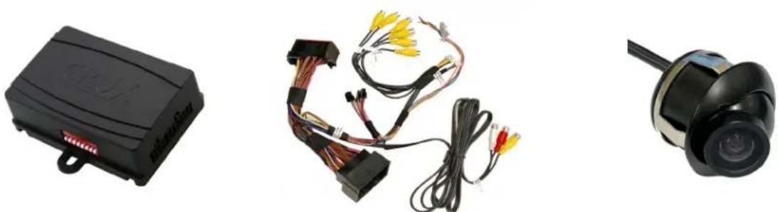
RFM-RAM1 Module RFM-RAM1 Harness CUB-15 Adjustable Angle Side Camera
(2 pieces)
OPTIONAL ADD-ON CAMERAS:
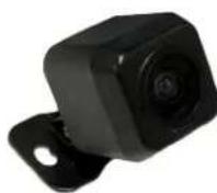
Optional add on cameras are available to complete the multi-view capability of the RFM-RAM1. Cameras available and sold separately include:
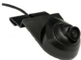
natural_image
Close-up of a black electronic device with a circular lens and cable (no visible text or symbols)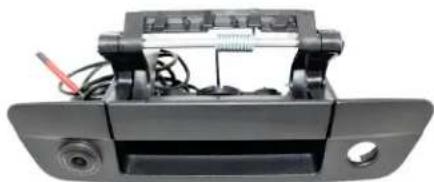
natural_image
Close-up of a black automotive rear bumper with visible electrical components and wiring (no text or symbols)CDR-31C Cargo Camera CDR-02 Tailgate Handle Camera
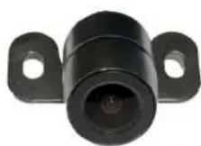

natural_image
Close-up of a black camera lens mounted on a metal bracket (no visible text or symbols)CFF-01 Bullet Type Front Camera CFF-02 Square Body Front Camera CFF-03 Grille Mount Front Camera

INSTALLATION DIAGRAM:
To Vehicle Harness

flowchart
graph TD
    A["To Radio"] --> B["CRUX Camera"]
    B --> C["Audio/Video Input"]
    B --> D["Front and Rear Camera Power Output 12V (purple/white)"]
    B --> E["Left and Right Camera Power Output 12V (green/white)"]
    B --> F["Cargo and Trailer Camera Power Output 12V (orange/white)"]
    B --> G["Video AUX Power Output 12V (red/white)"]
    B --> H["Front Camera Input"]
    B --> I["Right Camera Input"]
    B --> J["Left Camera Input"]
    B --> K["Cargo Camera Input"]
    B --> L["Aftermarket Backup Camera Input"]
    B --> M["Trailer Camera Input"]
    B --> N["Connect this 6-pin plug if OEM backup camera is being used"]
INSTALLATION INSTRUCTIONS:
natural_image
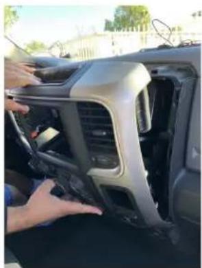
Person adjusting a car interior panel with visible dashboard and side-mounted air vent (no text or symbols)- Carefully remove the radio trim bezel by pulling outward.

natural_image
Interior view of a car battery pack with visible wiring and components (no text or symbols)- Unplug the connectors behind the radio trim bezel.
natural_image
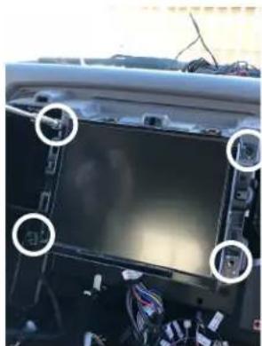
Interior view of a car dashboard with visible electronics and wiring (no text or symbols)- Remove the factory screen by removing the 4 screws on the corners.
natural_image
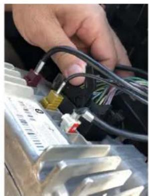
Close-up of hands connecting cables to an electrical component with visible wiring and a temperature scale (no text or symbols)
natural_image
Close-up of a hand holding a red plastic component with visible wiring and components (no text or symbols)
natural_image
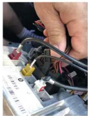
Close-up of hands installing or adjusting a black electronic component with wires and components (no visible text or symbols)- Unplug the factory 52-pin connector by pulling on the lock lever. 5. Connect the factory 52-pin
connector to the mating connector on the RFM-RAM1 T-harness.
natural_image
Close-up of hands connecting cables to electronic components (no visible text or symbols)
natural_image
Close-up of hands connecting cables to a device with visible wiring and connectors (no text or symbols)
natural_image
Close-up of a hand holding a black electronic device with wires and connectors (no visible text or symbols)-
Plug the 52-pin connector of the RFM-RAM1 T-harness to the radio and push in the lock lever.
-
Plug the Molex connectors from the T-harness to the module.

natural_image
Close-up of hands installing a black cable with a green connector (no visible text or symbols)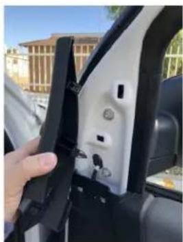
natural_image
Close-up of a hand inserting a car into a black plastic door, with no visible text or symbols.
natural_image
Close-up of a car's side panel showing black textured surface and a circular button (no text or symbols visible)
natural_image
Close-up of a mechanical component with a coiled black pipe and flanged parts, no visible text or symbols-
Plug the video RCA harness to the module.
-
Remove the door panels and side mirror to install the side mirror cameras. Run the cable through the boot for a clean install.
natural_image
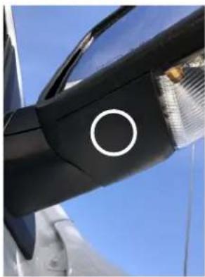
Close-up of a black mechanical component with a white circular mark and blue background (no text or symbols visible)- Use the provided hole saw to drill a hole on the side mirrors for the adjustable angle camera.
natural_image
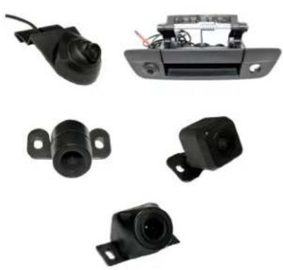
Collection of black automotive sensor components including camera, lens, and display unit (no text or symbols visible)- Mount the other optional front, rear and cargo cameras desired for the install. (Optional cameras sold separately. See page 1)

natural_image
Close-up of electrical wiring and components in a vehicle chassis (no visible text or symbols)- Run all the camera cables to the radio cavity.
natural_image
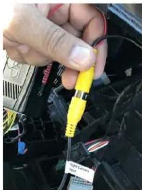
Close-up of a hand holding a yellow and black electronic component, with visible wiring and connectors (no text or symbols)- Plug the camera's male RCAs to the corresponding female RCAs of the RFM-RAM1 video harness. Each RCA is labeled for the input.
text_image
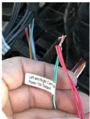
Left and Right Cable Power 12V Output- Connect the camera power wires to the corresponding camera power output wires of the RFM-RAM1 harness. Each wire is labeled.
natural_image
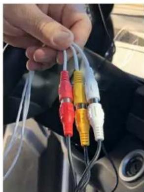
Close-up of a hand holding multiple colored audio/video cables (no visible text or symbols)- If you will be using the AV input option, plug in the AV RCAs of your device to the AV Input of the RFM-RAM1. Crux VCIP5 for HDMI input shown here (sold separately).
DIP SWITCH SETTINGS:
| DIP#ONOFF | — | — |
| 1 No Function – Leave OFF | ||
| 2 Front Camera ON Front Camera OFF | ||
| 3 Left Camera ON Left Camera OFF | ||
| 4 Right Camera ON Right Camera OFF | ||
| 5 Cargo Camera ON Cargo Camera OFF | ||
| 6 Trailer Camera ON Trailer Camera OFF | ||
| 7 | AUX A/V ON | AUX A/V OFF |
| 8 | Set to ON | |
OPERATION:
natural_image
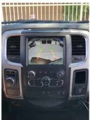
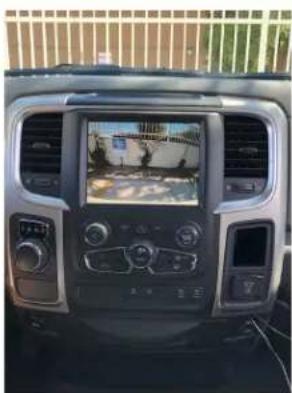
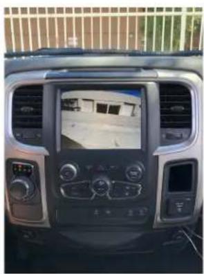
Interior view of a car dashboard with a digital display showing vehicle and sensor interface (no readable text or symbols)- Whether an aftermarket or OEM backup camera is used, putting the gear in reverse will automatically show the backup camera image on the screen.
natural_image
Interior view of a car dashboard with a digital display showing navigation and weather controls (no readable text or symbols)- Putting the gear to drive after the reverse process turns on the front camera for 7 seconds.
natural_image
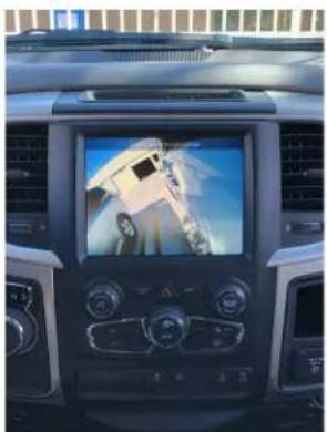
Interior view of a car dashboard with a digital display showing a vehicle's rear camera (no visible text or symbols)- Using the left and right turn signal triggers the respective side mirror mounted camera to show on the screen. To turn on automatic triggering, move the turn signal switch to the camera to be turned on and press the BACK button on the radio for 3-5 seconds.
text_image
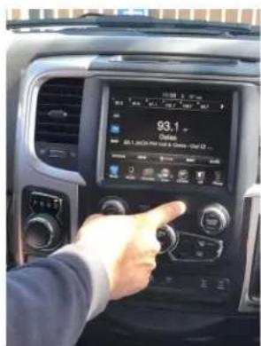
93.1 Select 93.1 selected car with a mode-Net 12...- To turn off the automatic triggering of the side mirror cameras, move the turn signal switch to the camera to be turned off and press the BACK button on the radio for 3-5 seconds. With the turn signal switch in nuetral, the same button turns on the VIM feature.
natural_image
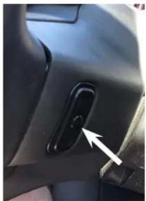
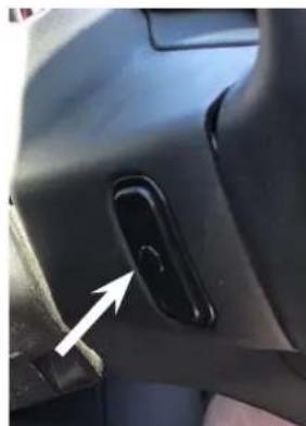
Close-up of a car interior component with a black handle and white arrow pointing to a button (no text or symbols visible)- To force view any of the cameras installed, press and hold the rear right side steering wheel control middle button once to enter force view mode and short press to toggle through all the different cameras.
natural_image
Close-up of a car's side panel showing a black handle and a white arrow pointing to a button (no text or symbols visible)- To use the AV input, press and hold the left rear side steering wheel control middle button to toggle to AV mode. Audio plugged in the AV RCAs will automatically be heard through the OE audio system. No need to plug to the AUX input of the vehicle.
Sample camera views and A/V Input:

natural_image
Interior view of a car dashboard with a digital display showing a road scene (no visible text or symbols)Cargo View
natural_image
Interior view of a car dashboard with digital display and control panels (no visible text or symbols)Trailer Hitch View
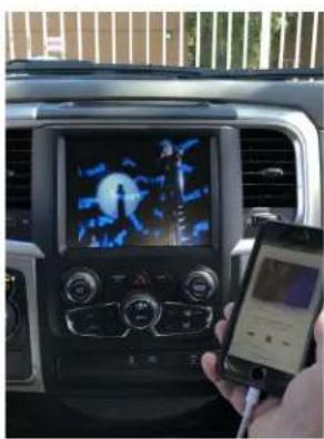
text_image
Car dashboard screen displaying a digital map with a person on the right, held by a hand holding a smartphone.A/V Input Mode
VEHICLE APPLICATIONS:
RAM
2013 - 2017 1500
2013 - 2017 2500
2013 - 2017 3500