
XOGRILL30L - Barbecue XO - Free user manual and instructions
Find the device manual for free XOGRILL30L XO in PDF.

| Product Type | Gas Barbecue Grill |
| Model | XOGRILL30L |
| Brand | XO |
| Main Cooking Area Dimensions | 665 sq. in. |
| Total Cooking Area (including warming rack) | 851 sq. in. |
| Gas Type | Natural Gas / Liquid Propane (convertible) |
| Main Burner BTU | 2 x 22,000 BTU (total 44,000 BTU) |
| Rear Rotisserie Burner BTU | 11,000 BTU |
| Burner Type | 1 Cast Stainless Steel H-Burner, 1 Infrared Burner |
| Cooking Grids | 2 x 5/16" Stainless Steel |
| Flame Tamers | 1 Stainless Steel Ceramic |
| Ignition Type | Push and Turn Flame Thrower (no battery) |
| Temperature Gauge | Hood-mounted |
| Control Panel Lights | LED Blue 12V |
| Interior Work Lights | 2 Halogen 12V |
| Warming Rack | Stainless Steel, Tilt and Lock Away |
| Rotisserie Kit | Optional |
| Cutout Dimensions (for built-in) | 10 7/8" H x 24" D x 28 3/4" W |
| Overall Dimensions (approximate) | 30" width (estimated) |
| Weight (approximate) | 150 lbs (estimated) |
| Power Supply | 12V AC via transformer (for lights) |
| Materials | Stainless Steel (hood, control panel, cooking grates), Cast Stainless Steel burners |
| Warranty | Limited Lifetime (main burners and housing), 5-year (briquette trays, grates, valves), 2-year (other components) |
| Use | Outdoor residential use only |
| Cleaning | Hand wash with mild soap; avoid abrasive cleaners; periodic burn-off |
| Safety Features | Automatic safety valve on rear burner, flame failure device, temperature gauge |
| Accessories Included | LP conversion kit, natural gas regulator, rotisserie motor bracket (motor optional) |
Frequently Asked Questions - XOGRILL30L XO
User questions about XOGRILL30L XO
0 question about this device. Answer the ones you know or ask your own.
Ask a new question about this device
Download the instructions for your Barbecue in PDF format for free! Find your manual XOGRILL30L - XO and take your electronic device back in hand. On this page are published all the documents necessary for the use of your device. XOGRILL30L by XO.
USER MANUAL XOGRILL30L XO
EVERYTHING YOU NEED TO KNOW ABOUT
YOUR

GAS GRILL
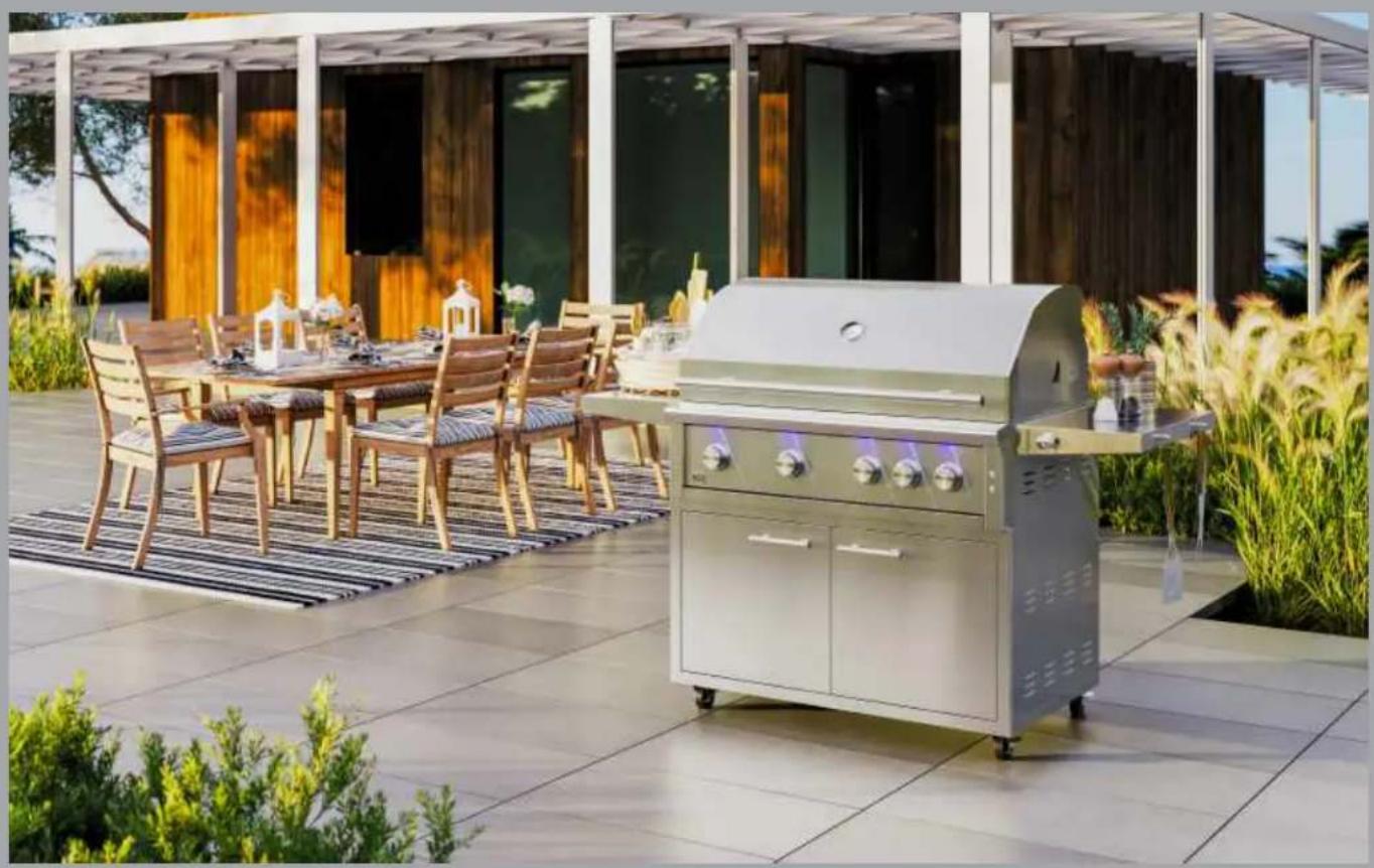
natural_image
Outdoor patio scene with a modern bench set, wooden table, chairs, and outdoor seating under a white arched shelter (no visible text or symbols)GAS GRILL
CARE & USE / INSTALLATION
I worked really hard on this manual - so please read it...
Installation, Care And Use Of Your XO Professional Cooking Product
THIS MANUAL MUST REMAIN WITH THE PRODUCT OWNER FOR FUTURE REFERENCE. RESIDENTIAL USE ONLY.
This manual covers the following XO products:
GRILL MODELS XOGRILL30L/N XOGRILL36L/N XOGRILL42L/N
DANGER
If you smell Gas:
- Shut off gas to appliance
- Extinguish any open flames
- Open Lid
- If odor continues keep away from appliance and immediately call your gas supplier or your fire department.
WARNING
- Do not store or use gasoline or other flammable liquids or vapors in the vaccinity of this or any other appliance!
- An Ip cylinder not connected for use shall not be stored in the vaccinity of this or any other appliance!

natural_image
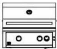
Line drawing of a front panel with buttons and a lid (no text or symbols)
natural_image
Line drawing of a kitchen appliance with front panel, door, and side-mounted legs (no text or symbols)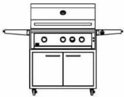
natural_image
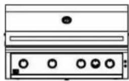
Line drawing of a vintage kitchen appliance with front panel, doors, and control buttons (no text or symbols)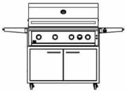
natural_image
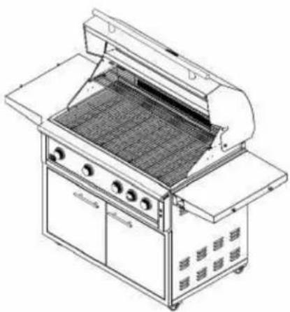
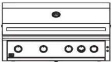
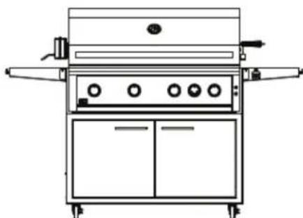
Line drawing of a vintage kitchen appliance with front panel and control panels (no text or symbols)*Grill Head Shown With Optional Carts Above
FOR OUT DOOR USE ONLY
IMPROPER INSTALLATION, ADJUSTMENT, ALTERATION, SERVICE OR MAINTENANCE CAN CAUSE PROPERTY DAMAGE, INJURY OR DEATH. READ THIS MANUAL THOROUGHLY BEFORE INSTALLATION, USE OR SERVICING OF THIS EQUIPMENT
NOTE TO INSTALLER
This manual must remain with grill. Check your local building codes for proper method of installation. In the absence of local codes, this unit should be installed in accordance with National Fuel Gas Code No. ANSI Z21.58D-2002 USA or CAN/CGA-B149.1/.2 Natural Gas/Propane Code. (Canada) latest edition or the National Electrical Code ANSI/NFPA No. 70 or the Canadian Electrical Code CGA 1.6b2005 or latest edition.

WHERE THINGS ARE
XO BBQ Models....2
Unique Features & Benefit 4
Product Specification 5
Overall Grill Dimensions....6
Control Identification 7
Warning Instructions 8
NOTICE: Commonwealth Of Massachusetts 9
Grill Location....10
Location Of Your Grill (Using Your Grill During In Windy Conditions)....11/12/13/14
Built-In Grill Dimensions 15
Vent Registers 16
Built-In Sleeve Dimensions....17
Electrical Requirements & Hook-up....18
Wiring Schematics....19
LP Gas Cylinder Safety 20
Gas Requirements & Hook-up....21/22/23/24
Important Safety Grilling Information 25
Converting Your Gas Grill....26/27
Converting Your Gas Grill Type 28
Regulator Gas Conversion 29
Lighting The Burners 30
Manually Lighting The Grill 31
Burner Type Identification 32
Using The XO Grill....32
Direct Cooking Method 33
Indirect Cooking Method....33
Using The Rotisserie 34
Cooking Tips....35
Burner Cleaning And Adjustment....36
Warnings 37
Grill Cleaning Methods 37
Cleaning The Grill....38/39
Light Bulb Replacement 40
Warranty 41
How To Order Repair Parts....42
Contacting XO 43
XO Parts List.... 44
Parts Diagram....45
Service Record....46
MEET YOUR XO
UNIQUE FEATURES AND BENEFITS
natural_image
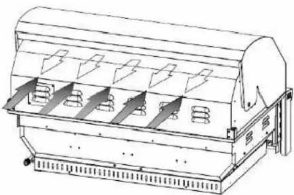
Line drawing of a portable electric grill with grating and side-mounted dish (no text or symbols)The XO gas grill has some of the most unique grilling features that will enhance your grilling experience and make you that "master chef". These features include Stainless Steel Grills, enhanced briquette and flame tamers to create even heat and minimize flair-ups, IR Burner and Cast Stainless H-burner designs to enhance the overall searing of your food.

natural_image
Pure geometric diagram of a rectangular grid with diagonal lines and no text or symbolsProfessional Grade stainless steel cooking grates allow for the food to be cooked quickly and with control. The heavy duty grates heat up evenly and sear the natural juices into the food.

natural_image
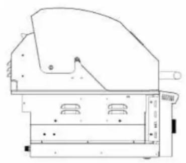
Isometric line drawing of a multi-level architectural structure with grid-like panels (no text or symbols)Unique design technology is placed into this “one of a kind” briquette and Flame Tamer system. This briquette system pump’s even heat onto the food at the same time as vaporizing overflow juices that create added flavor in the food.

natural_image
Pure technical line drawing of a mechanical component with no text or symbolsProfessional cast stainless H-Style burner technology is used in the XO gas grill. This new Burner has “even heat distribution” that allows for even heating for the front and back across the entire heat zone.
natural_image
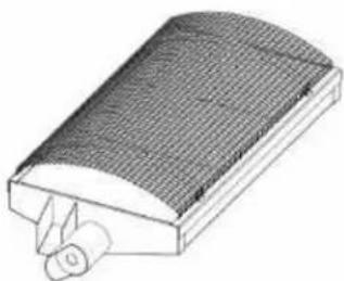
3D illustration of a curved, textured object with a small protrusion at the base (no text or symbols)Your XO grill includes a Infrared Burner produced in California by the #1 manufacturer of infrared technology. Temperature ranges from 300 to 1000 degrees. This burner will soon become your favorite.
PRODUCT SPECIFICATIONS
| Description | 30" XO GRILL | 36" XO GRILL | 42" XO GRILL42 |
| Main Cooking Area Dimension 665 869598 | |||
| Total Cooking Area Sq. In.(Includes Warming Rack) | 851 | 978 1235 | |
| Gas Type NAT/LP NAT/LP | NAT/LP | ||
| LP Conversion Kit Packed w/Grill | Packed w/Grill | ||
| Orifices Main Burners N T Gas | 2 - 2.26 mm | 3 - 2.26 mm | 4 - 2.26 mm |
| Orifices Main Burners L Gas 3 - | 1.40 2mm 1.40 mm | ||
| Orifices Rear Burner N T Gas 1.5 mm | 1.55mm | ||
| Orifices Rear Burner L Gas | 1.1 mm | 1.1 mm 1.1 mm | |
| Burner Type | 1- Cast SS1-IR Burner | 2- Cast SS1-IR Burner | 3- Cast SS1-IR Burner |
| Burner BTU's (Each/Total) | 22,000 / 44,000 | 22,000 / 66,000 | 22,000 / 88,000 |
| Cooking Grids | 2- 5/16" SS | 3 - 5/16" SS | 4 - 5/16" SS |
| Flame Tamers | 1 - SS Ceramic | 2 - SS Ceramic | 3 - SS Ceramic |
| Heat Zone Dividers | 1 - SS(Removable) | 2 - SS(Removable) | 3 - SS(Removable) |
| Rear Rotisserie Burner | 11,000 BTUCeramic | 11,000 BTUCeramic | 11,000 BTUCeramic |
| Rotisserie Kit | Optional | Optional | Optional |
| Lid Assembly | Fully Weldedw/PolishedEdges | Fully Weldedw/PolishedEdges | Fully Weldedw/PolishedEdges |
| Control Panel | Fully Welded | Fully Welded | Fully Welded |
| Drip Tray | Fully Welded | Fully Welded | Fully Welded |
| Ignition Type (No Battery) | Push And TurnFlame Thrower | Push And TurnFlame Thrower | Push And TurnFlame Thrower |
| Warming Rack | SS Tilt AndLock Away | SS Tilt AndLock Away | SS Tilt AndLock Away |
| Temp Gauge | Hood | Hood | Hood |
| Control Panel Lights | LED Blue 12V | LED Blue 12V | LED Blue 12V |
| Interior Work Lights | 2 - Halogen 12V | 2 - Halogen 12V | 2 - Halogen 12V |
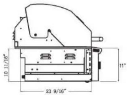
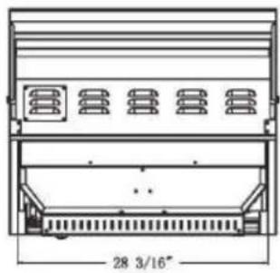
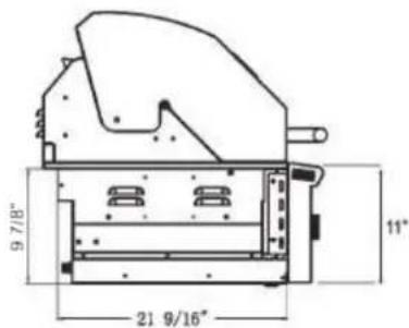
| Cutout Dimensions For Grill | 10 7/8H x 24Dx 28 3/4W | 10 1/8H x 22Dx 34 3/4W | 10 7/8H x 24Dx 40 3/4W |
PLEASE READ AND FOLLOW ALL SAFETY INSTRUCTIONS
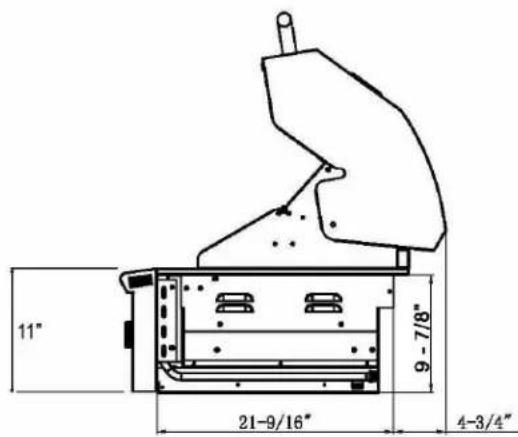
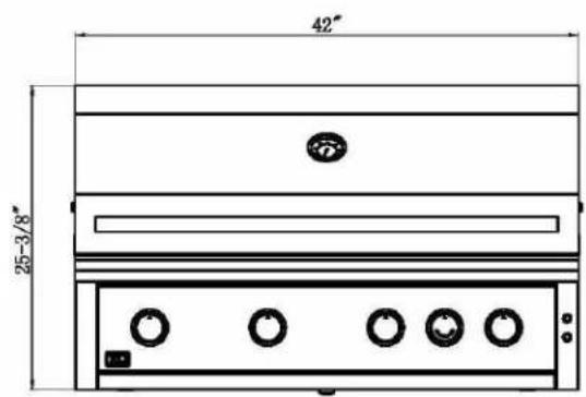
OVERALL
GRILL DIMENSIONS
XO GRILL 30


XO GRILL 36

XO GRILL 42

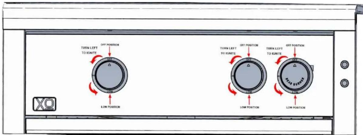
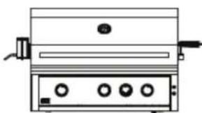
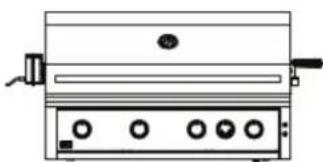
CONTROL
IDENTIFICATION
30" XO GRILL

36" XO GRILL
42" XO GRILL


IGNITION POSITION:
Push Burner control knob "IN" and to the "LEFT. Wait 3-5 Seconds and Ignite by hearing "CLICK". Always turn to the "OFF" position when done.
YOUR SAFETY MATTERS

WARNING

- Read this manual carefully and completely before using your grill, to reduce the risk of fire, burn hazard or other injury and to ensure proper installation and servicing.
- Never use rusted, dented or damaged propane cylinders. Never store additional or empty propane cylinders in the grill cabinet or in the vicinity of this or any other gas or electrical appliance. Do not store propane cylinders indoors or on their sides for gas may escape. Gas cylinders are highly flammable
- No Children should ever be left alone or unattended in an area where a grill is located. Place your grill well away from areas where children play. Do not store items that may interest children in or around the grill, in the cart or in the enclosure or Island.
- Never move the grill when hot. When in use, portions of the grill are hot enough to cause severe burns.
• Always maintain the required clearances from combustibles as detailed. The grill is designed for outdoor use only. Never use in a garage, building, shed, breezeway or other enclosed area. Do not use this grill under any unprotected overhead combustible construction. Combustible material exposed to heat will catch on fire
- Gas grills are not designed or certified for and are not to be installed in or on a recreational vehicles, portable trailers, boats or any other moving installation including commercial use.
• Always have a Fire Extinguisher accessible — never attempt to extinguish a grease fire with water or other liquids.
- Store your grill in a well-ventilated area. If stored indoors, detach and leave L.P. cylinder outdoors in a well-ventilated area away from heat and away from where children may tamper with it. Always leave tank outdoors.
- Keep any electrical supply cord and the fuel supply hose away from any heated surfaces. Electrical cords should be placed away from walkways to avoid tripping hazard.
- Do not repair or replace any part of the grill unless specific recommended in this manual. Other service should be performed by a certified and qualified BBQ technician.
- If the grill is installed by a professional installer or technician, be sure that he/she shows you where your gas supply shut-off is located. All gas lines must have a shut-off that is readily and easily accessible. If you smell gas, check for gas leaks immediately. Check only with a soap and water solution. Never check for gas leaks with an open flame
- Inspect the LP gas supply hose prior to each use of the grill. If there is evidence of excessive abrasion or wear, or the hose is cut, it must be replaced before using the grill.
- The outdoor cooking gas appliance and its individual shutoff valve must be disconnected from the gas supply piping system during any pressure testing of that system at test pressures in excess of 0.5 psi (3.5 kPa).
- The outdoor cooking gas appliance must be isolated from the gas supply piping system by closing its individual manual shutoff valve during any pressure testing of the gas supply piping system at test pressures equal to or less than 1/2 psi (3.5 kPa).
NOTICE: COMMONWEALTH OF MASSACHUSETTS
- Massachusetts requires all gas be installed using a plumber or gas fitter carrying the appropriate Massachusetts license.
- All permanently-installed natural gas or propane installations require a "T" handle type manual gas valve be installed in the gas supply line to this appliance.
- This does not apply to portable propane installations using a 20 pound cylinder.

WARNING! CALIFORNIA PROPOSITION 65
- The burning of gas cooking fuel generates some by-products which are on the list of substances which are known by the State of California to cause cancer or reproductive harm.
- California law requires businesses to warn customers of potential exposure to such substances. To minimize exposure to the substances, always operate this unit according to the use and care instructions found in this manual. Be certain to provide adequate ventilation when cooking.
- Warning: Handling the brass material on this product exposes you to lead, a chemical known to the state of California to cause cancer, birth defects or other reproductive harm. (Wash hands after handling this product.)
- For more information go to this website: www.p65warning.ca.gov

WARNING

Combustion byproducts produced when using this product contains chemicals known to the state of California to cause cancer, birth defects or other reproductive harm.
Handling the brass material on this product exposes you to lead, a chemical known to the state of California to cause cancer, birth defects or other reproductive harm (wash hands after handling this product)
For more information go to this website www.P65warnings.ca.gov


GRILL LOCATION


- Never install this product into a combustible enclosure without an insulated jacket. Doing so could result in fire, property damage and personal injur. Combustible material is "anything" that can catch on fire
- Never locate the grill under a roof or overhang, in a building, garage, shed or other such enclosed area.
• Installation must conform with local codes or, in the absence of local codes, with either the National Fuel Gas Code, ANSI Z223.1/NFPA 54, Natural Gas and propane Installation Code, CSA B149.1, or Propane Storage and Handling Code, B149.2, in Canada.
WHERE IS THE WIND COMING FROM?
When selecting a suitable location, consider important factors such as exposure to the wind and foot-traffic patterns
If you have a free standing grill, position it so the prevailing wind blows into the front control panel (at your back when grilling), supporting the proper front of BBQ to rear of BBQ airflow. Built-in grills located in areas with prevailing winds should be protected by a wind barrier.
Winds hitting the back of the grill directly may cause problems, as well as wind blowing along the hood opening
natural_image
Technical line drawing of a mechanical device with internal components and directional arrows (no text or symbols)HOW LONG IS YOUR GAS RUN GOING TO BE?
Keep all gas supply lines as short as possible because gas lines lose pressure over distance and with each elbow and tee that is added. This drop in pressure affects grill performance.
CHECK THE BBQ IS LEVEL?
Proper leveling during installation is critical. A grill that is out of level will cause erratic burner combustion and inefficient, uneven heating. A carpenter's spirit level should be used to level the grill both front-to-back and side-to-side.
If the floor is uneven or has a decided slope, re-leveling may be required each time you move a freestanding unit.

natural_image
Technical line drawing of a mechanical device with multiple slots and mounting brackets (no text or symbols)Be sure wind doesn't blow into the back of the hood gap.
USING YOUR GRILL IN WINDY CONDITIONS:
- As a high-performance gas appliance, your XO grill requires significant amounts of air to support the burner combustion process. Your grill has been engineered to take air in through the control panel area, and exhaust the combustion out through the gap between the front and rear hoods
- Using your grill in windy conditions can disrupt the proper flow of air through you grill, leading to reduced performance, or in certain severe cases, causing heat buildup in the control panel area. This can lead to problems such as having the control knobs getting hot or melting, or burn hazards when the control panel surfaces become too hot to touch.
- If you have a freestanding grill, it is best to position the unit so the prevailing wind blows into the front control panel (or at your back), thus supporting the proper airflow. Winds hitting the back of the grill directly are the most likely to cause problems, although wind blowing along the hood gap can also be a problem.
- Please note that damage to your grill resulting from use in windy conditions, such as melted knobs or igniter wires, or control panel discoloration from heat build-up, are excluded from warranty coverage.
- Outdoor grilling can create more heat than indoor kitchen ranges.
BUT THERE ARE A FEW THINGS YOU CAN DO TO FURTHER PREVENT THE POSSIBILITY OF IMPROPER HEAT BUILDUP:
- If you suspect the grill is overheating, using an heat resistant mitt, open the front hood. Then adjust the burner control knob to a lower setting. Do not grab the knobs without testing the temperature of them.
• Install your grill with a wind break behind it. This is a wall, fence or anything that will disrupt the wind directly hitting the gas grill. - Situate the grill so prevailing winds are not blowing into the rear of the grill.
- On windy days, be careful not to leave the hood down for more than 15 minutes when the burners are on high. (Never leave the grill unattended when in operation)

Wind hitting the back of the grill can disrupt proper exhaust.
- The XO Built in model is designed for easy installation into a non-combustible masonry enclosure.
- The BBQ must be surrounded by non-combustible material like Brick or Hardibacker but should never be installed into a wood island without a insulated sleeve (accessory) surrounding the Gas Grill.
5" Hood Clearance
natural_image
Technical line drawing of a mechanical component or housing (no text or symbols visible)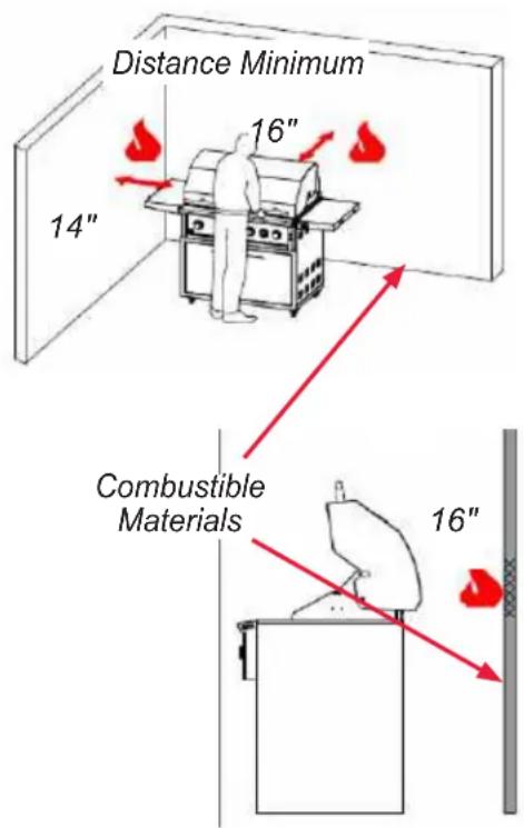
- The grill drops into the cutout opening and sits on the sides and back of the grill. There is no need to fasten the grill to the island. The gas grill must be able to be removed for general maintenance so do not grout sides or fasten in.
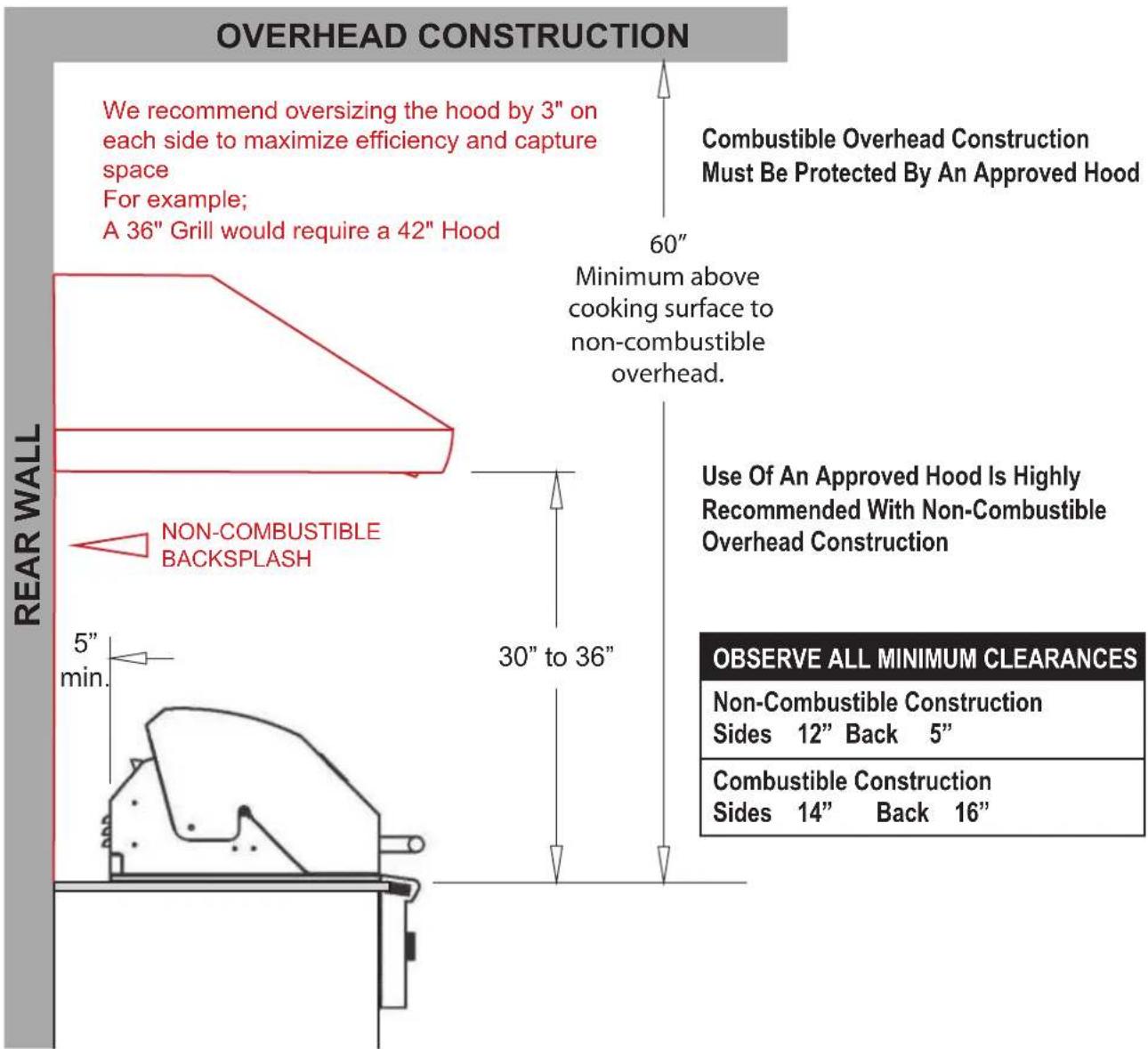
- For the hood to open there is a minimum of 5" clearance behind the hood. There is a required 12" clearance on each side of the Gas Grill. Remember that combustible materials should not be located behind the grill, because the 5" space doesn't satisfy the distance required from a combustible surface. See below clearance to combustibles.
CLEARANCE TO COMBUSTIBLE CONSTRUCTION:
Minimum clearance from sides and back of unit to adjacent combustible construction below top of unit are 14" from sides and 16" from back. Use your grill at least 16" away from any wall or surface.
Use your grill 16" or more away from any combustible objects that can melt or catch fire such as vinyl or wood siding, fences, overhangs, or any other sources of ignition; including pilot lights and live electrical appliances.
Do not use your grill under any overhead combustible construction. Never use your gas grill in a garage, porch, shed, breezeway, or any other enclosed area. Never use your gas grill on a balcony, deck, or patio above the ground floor of your home.

WARNING

Installing this product into a combustible enclosure without an insulated jacket could result in fire, property damage and personal injury.
- If installed under any combustible construction the area above the cooking surface of the grill must be covered with an approved exhaust hood.
- It is highly recommended the hood be sized with a 3" overhang on all exposed sides.
• The exhaust hood shall provide no less than 1,000 CFM of proper exhaust ventilation. - The exhaust hood must be approved for outdoor installation and used with a dedicated GFCI branch circuit.
TYPICAL EXHAUST HOOD INSTALLATION
OUTDOOR RATED EXHAUST HOODS
AVAILABLE IN THREE SIZES
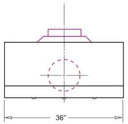

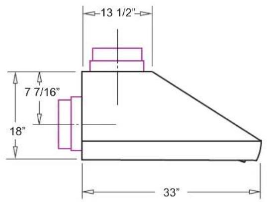
MODEL: XOGVENT36
36" Wide - use with XOGRILL30 & XOGRIDDLE30
MODEL: XOGVENT42
42" Wide - use with XOGRILL36
MODEL: XOGVENT48
48" Wide - use with XOGRILL42
All Models:
33" Deep
18" High to the top of the Canopy
10" Dia. Exhaust Top or Rear
All Models have the following features:
Top or Rear Venting
304 Stainless Steel Construction
Professional Stainless Steel Baffle Filters
Four LED Lamps
Rotary Controls
Two High Velocity Blowers capable
of exhausting up to 1,200 CFM
Matching SS Top Duct Cover

natural_image
3D rendering of a metallic industrial ventilation duct with slatted ventilation slots (no text or symbols)BUILT IN GRILL DIMENSIONS
Must conform with local codes or, in the absence of local codes, with either the National Fuel Gas Code, ANSI Z223.1/NFPA 54, or the Natural Gas and Propane Installation Code, CSA B149.1, or the Propane Storage and Handling Code, CSA B149.2, or the Standard for Recreational Vehicles, ANSI A119.2/NFPA 1192, and CSA Z240 RV Series, Recreational Vehicle Code, as applicable
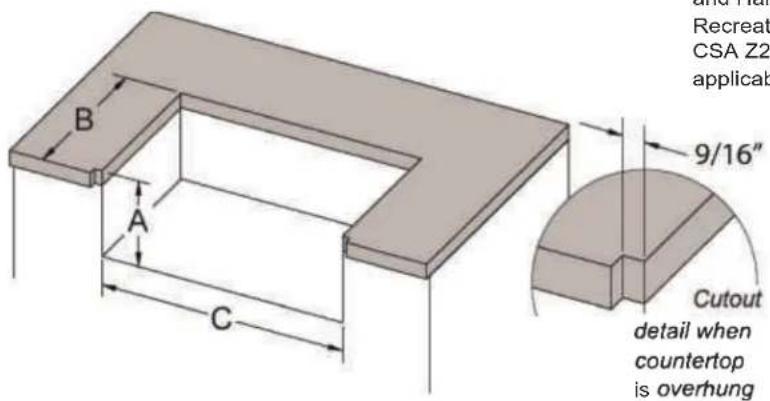
| A | B | C | ||
| 30" 2 Burner | XOGRILL30 | 10 7/8 | 24" | 28 3/4" |
| 36" 3 Burner | XOGRILL36 | 10 1/8" | 22" | 34 3/4" |
| 42" 4 Burner | XOGRILL42 | 10 7/8" | 24" | 40 3/4" |
30" GRILL
natural_image
Technical line drawing of a mechanical or electrical component with no visible text or symbols36" GRILL

natural_image
Technical line drawing of a mechanical or electrical component with no visible text or symbols42" GRILL
natural_image
Technical line drawing of a mechanical component with no visible text or symbolsISLAND VENTING
LP Gas
flowchart
graph TD
    A["Clamp down flexline"] --> B["QCC-1/OPD Tank"]
    B --> C["CSA Approved Propane Regulator"]
    C --> D["Stainless Flexline"]
    D --> E["CSA Approved Rubber Gas Hose"]
    E --> F["Vented Access Door"]
    F --> G["Non-combustible Construction"]
    G --> H["Vented on BOTH SIDES of Island"]
    style A fill:#f9f,stroke:#333
    style B fill:#ccf,stroke:#333
    style C fill:#cfc,stroke:#333
    style D fill:#fcc,stroke:#333
    style E fill:#cff,stroke:#333
    style F fill:#ffc,stroke:#333
    style G fill:#fcc,stroke:#333
    style H fill:#fff,stroke:#333
INSULATED SLEEVE INSTALLATION INSTRUCTIONS
IMPORTANT: Before you build the frame, you must take into consideration the total weight of the sleeve, grill and any finishing materials
Review the table on the next page for the proper framing dimensions for the insulation sleeve. Determine the entry point for both the gas inlet and electric connections. Make the 4" square holes for gas and electrical connections (rear or bottom access) based on your requirements. Note that the gas and electrical connections are located on the right side.
A "Level" should be used to assure that the framing is level, both front to back and side to side.
NOTE: Never under any circumstance should you install the transformer or run a gas hose in between the grill and the
SLEEVE INSTALLATION
Position the sleeve into the frame. No part of the combustible enclosure can protrude above the top surface or in front of the face surface of the liner.
GRILL INSTALLATION
Use the proper equipment to support the grill. Place the grill into the sleeve and place it over the sleeve lip across the back and sides. The liner is designed to support the grill without additional fasteners.
FINISHING
If desired any gap remaining between the sleeve and the combustible enclosure may be filled with a non-combustible sealant
NOTE: Do not store any chemicals in the island. Pool chemicals or any chemical will corrode the gas hoses and manifold / valves and may cause a leak resulting in an explosion and/or bodily harm or death. Warranty on all equipment will be void if chemicals are stored in the island.
INSULATED
BUILT-IN SLEEVE
WARNING: Combustible Material will ignite if used without an insulated liner to protect the combustible material.
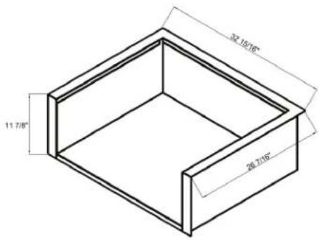
MODEL# XOG30JACKET 30" SS Insulated Sleeve

natural_image
Line drawing of a double boiler with control panel (no text or symbols)Overall Dimensions
| Width | Height | Depth |
| 32 15/16 | 11 7/8 | 26 7/16 |
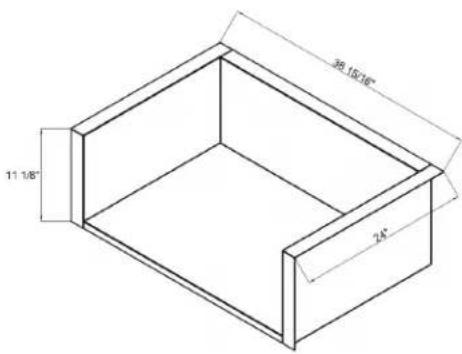
MODEL# XOG36JACKET 36" SS Insulated Sleeve
natural_image
Line drawing of a front view of a double boiler or air conditioner unit (no text or symbols)Overall Dimensions
| Width | Height | Depth |
| 38 15/16 | 11 1/8 | 24 |
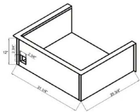
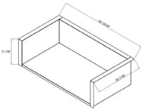
MODEL# XOG42JACKET 42" SS Insulated Sleeve
natural_image
Line drawing of a double-door air conditioner unit with control buttons (no text or symbols)Overall Dimensions
| Width | Height | Depth |
| 44 15/16 | 11 7/8 | 26 7/16 |
Cut - Out Dimensions
| Width | Height | Depth |
| 31 1/4 | 12 | 25 3/4 |
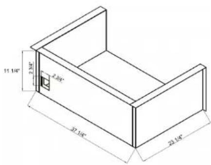
Cut - Out Dimensions
| Width | Height | Depth |
| 37 1/4 | 11 1/4 | 23 1/4 |
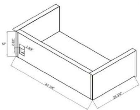
Cut - Out Dimensions
| Width | Height | Depth |
| 43 1/4 | 12 | 25 3/4 |
ELECTRICAL REQUIREMENTS AND HOOK-UP

WARNING! ELECTRICAL GROUNDING
- Product installation must meet local electric codes or, in the absence of local codes, the latest edition of the National Electrical Code ANSI/NFPA No. 70 or the Canadian Electrical Code CGA 1.6b2005.
- Use only a Ground Fault Interrupter (GFI) protected circuit with this outdoor cooking gas appliance.
- This grill is equipped with a three prong (grounding) electric plug for your protection against shock hazard and must be plugged directly into a properly grounded three prong outlet. Never cut or remove the grounding prong from this plug.
- Use only extension cords with a 3 prong grounding plug, rated for the power of the equipment, and approved for outdoor use with a "W-A" marking.
- To protect against electric shock, do not immerse any part of the power cord, an extension cord or any plugs in water or other liquid.
- Unplug the product from the outlet when not in use and before cleaning. Allow it to cool before putting on or taking off parts.
- Do not let the cord touch hot surfaces.
- Do not use an outdoor cooking gas appliance for purposes other than intended.
- Do not operate any outdoor cooking gas appliance with a damaged cord, plug, or after the appliance malfunctions or has been damaged in any manner. Contact the dealer for repair.

WARNING

CALIFORNIA PROPOSITION 65
The electrical supply cord and plug of the Rotisserie and Transformer contain chemicals, including lead, known to the State of California to cause cancer, and birth defects or other reproductive harm. Wash hands after handling.


CAUTION

To protect against shock hazard risk, connect only to properly Grounded Outlet.

WARNING

This appliance, when installed, must be electrically grounded in accordance with local codes or, in the absence of local codes, with the National Electrical Code, ANSI/NFPA 70, or the Canadian Electrical Code, CSA C22.1. Keep any electrical supply cord and the fuel supply hose away from any heated surface.
WIRING SCHEMATICS
NOTE: This grill uses a transformer to provide power to the LED lights and work lights. The transformer should be secured to the island walls or cart back wall. Plug only into a Ground Fault Interrupter (GFI) protected circuit.

WIRING SCHEMATICS
NOTE: On install the electrical transformer to the cart use the 4 Bolts provided in your hardware pack. The transformed has 4 holes that will match up to the holes on the back panel of the cart. face the transformer main electrical wire "facing down" and the wire from the gas grill will connect securely into the top of the transformer making a watertight fit.

natural_image
Technical line drawing of a mechanical assembly with mounting holes and a central component (no text or symbols)
WARNING

Do not store a spare LP-Gas tank under or near this appliance. Never fill the tank beyond 80 percent full; and if the information is not followed exactly, a fire causing death or serious injury may occur.
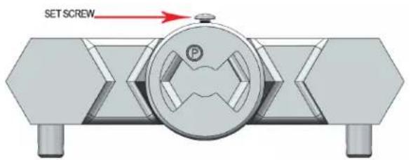
LP Gas grill models are designed for use with a standard 20lb. Liquid Propane Gas (LP Gas) tank (sold separately). Never connect your gas grill to an LP Gas tank that exceeds this capacity. A tank of approximately 12 inches in diameter by 18-1/2 inches high is the maximum size LP Gas tank to use. You must use an "OPD" gas tank which has a listed Overfill Prevention Device. This safety feature prevents tank from being overfilled which can cause a malfunction of the LP Gas tank.
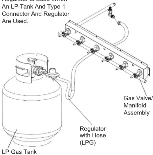
The LP Gas tank must be constructed and marked in accordance with the Specifications for LP-Gas Cylinders of the U.S. Department of Transportation (D.O.T. or the National Standard of Canada, CAN/CSA-B339, Cylinders, Spheres and Tubes for Transportation of Dangerous Goods, and Commission; as applicable.
The LP Gas tank must have a shutoff valve, terminating in an LP Gas supply tank valve outlet, that is compatible with a Type 1 tank connection device. The LP Gas tank must also have a safety relief device that has a direct connection with the vapor space of the tank. The tank supply system must be arranged for vapor withdrawal.
The LP Gas tank must have a collar to protect the tank valve. Never connect an unregulated LP gas tank to your gas grill. The gas regulator assembly supplied with
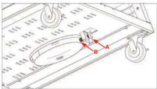
NOTE: LP Tank is secured by a Set Screw (A) and secures the tank by locking it down (B)
Page 20
your gas grill is adjusted to have an outlet pressure of 11" water column (W.C.) for connection to an LP gas tank. Only use the regulator and hose assembly supplied with your gas grill.
Replacement hose and regulator assembly must be identical to those listed in the parts list of this Operator's Manual as specified by XO.
Have your LP Gas dealer check the release valve after every filling to ensure it remains free of defects. Always keep LP Gas tank in upright position. Do not subject the LP Gas tank to excessive heat.
Never store an LP Gas tank indoors. If you store your gas grill in the garage always disconnect the LP Gas tank first and store it safely outside.
LP Gas tanks must be stored outdoors in a well-ventilated area and out of the reach of children. Disconnected LP Gas tanks must not be stored in a building, garage or any other enclosed area.
The regulator and hose assembly can be seen by opening the cart or island doors. They must be inspected before each use of the grill. If the hose is damaged in any way, it must be replaced prior to using the grill again.
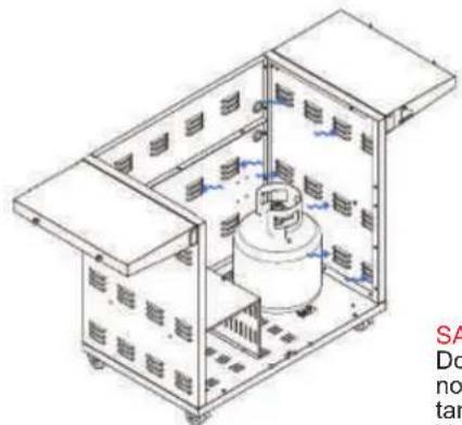
The Gas Grill is setup to operate with a LP Gas Cylinder equipped with an OPD (Overfilling Prevention Device)
BBQ Cart has "Air Vents" on side to allow excess vapor to be released.
natural_image
Isometric technical diagram of a mechanical device with internal components and no visible text or symbolsSAFETY NOTICE
Do not leave tank on while not in use. Always turn tank to OFF position. Vapor will be released if the tank is heated up while not in use.
GAS REQUIREMENTS AND HOOK-UP
LP GAS MODEL ONLY - TYPE 1 CONNECTION WITH REGULATOR AND HOSE TO YOUR LP GAS TANK.
Connect and tighten the swivel nut of the gas hose to the grill manifold shown below.
Turn all Control Knobs to the OFF position. Inspect the valve connection port and regulator assembly for damage or debris. Remove any debris. Never use damaged equipment.
Connect the regulator assembly to the tank valve and HAND TIGHTEN nut clockwise to a full stop. DO NOT use a wrench to tighten because it could damage the Quick Coupling Nut and result in a gas leak/fire hazard
Open the tank valve a full turn (counterclockwise) and use a soapy water solution to check all connections for leaks before attempting to light your grill. See "Check All Connections for LP Gas Leaks." If a leak is found, turn the tank valve off and do not use your grill until the leak is repaired.


WARNING

Failure to read and follow the Use and Care Instructions could result in a fire or explosion that could cause serious bodily injury, death, or property damage.
CHECK ALL CONNECTIONS FOR LP GAS LEAKS.
Never test for leaks with an open flame. Prior to first use, at the beginning of each season, or every time your LP Gas tank is changed, you must check for gas leaks.
FOLLOW THESE THREE STEPS:
- Make a soap solution by mixing one part liquid detergent and one part water.
- Turn the grill Control Knobs to the full OFF position, then turn the gas ON at source.
- Apply the soap solution to all gas connections. If bubbles appear in the soap solution the connections are not properly sealed. Check each fitting an tighten or repair as necessary.
NOTE: No Appliance Regulator Is Used When An LP Tank And Type 1 Connector And Regulator Are Used.
GAS REQUIREMENTS AND HOOK-UP (CONT'D.)
CAUTION: When the appliance is not in use the gas must be turned off at the tank. Place dust cap on cylinder valve outlet whenever the cylinder is not in use. Only install the type of dust cap on the cylinder valve outlet that is provided with the cylinder valve. Other types of caps or plugs may result in leakage of propane.


- Do not store spare LP cylinder within 10 feet (3m) of this appliance.
- Do not store or use gasoline or other flammable liquids and vapors within 25 feet (8m) of this appliance.
- When cooking with oil/grease, do not allow the oil/grease to get hotter 350^ F ( 177^ C).
- Do not leave oil/grease unattended.
DISCONNECTING A LIQUID PROPANE GAS (LPG) TANK FROM YOUR GRILL
- Make sure the Burner Valves and LP Gas tank valve are off. (Turn clockwise to close.)
- Detach the hose and regulator assembly from the LP Gas tank valve by turning the Quick Coupling Nut counterclockwise.
- Do not use a wrench or any tools when turning the Quick Coupling Nut.

WARNING

If you have a gas leak that cannot be repaired, turn off the gas at the source and disconnect the fuel line from your grill. Call your gas supplier or fire department for repair assistance
NATURAL GAS CONNECTION KIT INCLUDED WITH GAS GRILL
- The Natural Gas regulator and 1/2F to 1/2M Brass connection is included in the Gas Grill.
- The Gas Grill Regulator can be Natural Gas or Liquid Propane (LP) Gas compatible.
- Always use a Professional Installer when connection gas.

- Gas grill manifold ends in a 1/2" male thread and "Grip Nut" for wrench.
- Connect the brass fitting to the end of the manifold. Use a wrench on the manifold to not allow it to move.
- Always use plumbers putty or gas tape on the male threads to seal the connection.
- and make the gas regulator sure the "In" and "Out" are correct. There is only one way the regulator works.
- A gas flex line or hose can then be used to the house gas.
- Test the connection with soupy water and make sure there are no leaks.
GAS REQUIREMENTS AND HOOK-UP (CONT'D.)
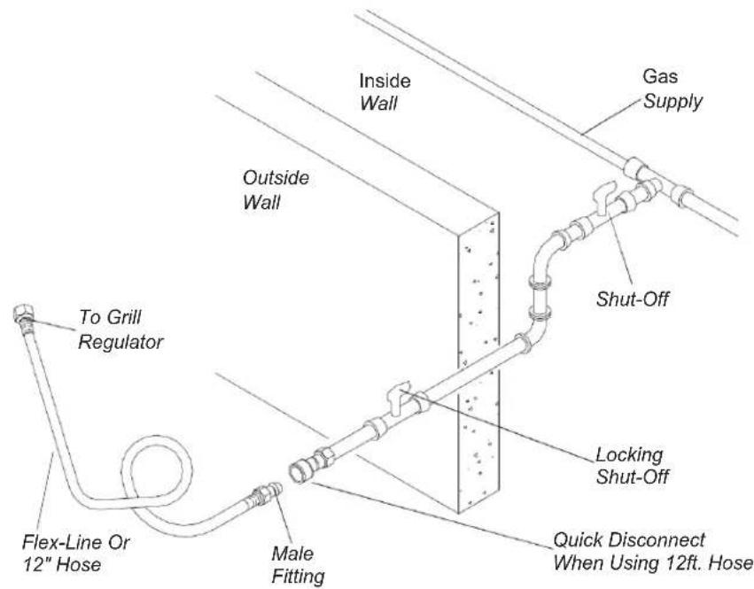
CONNECTING TO A PERMANENTLY PLUMBED GAS LINE
Follow the diagrams below when connecting gas to your grill from a natural gas line or a permanently plumbed hard piped LP connection.
NOTE: When using a portable cart mounted grill, the use of a 12ft. Q.C. Hose is recommended from grill to gas supply.
Whether the grill is built-in to a permanent structure, the use of a S/S Flex-Line is recommended from grill to gas supply.
Connect the Swivel nut of the flex-line or 12' Natural Gas Hose to the horizontal fitting of the regulator as shown and connect the other end to the gas supply line from your home. Read and follow the "Gas Safety Instructions" on page 22.

GAS REQUIREMENTS AND HOOK-UP (CONT'D.)
GAS SAFETY INSTRUCTIONS
Your natural gas grill is designed for use with natural gas (NG) or LP gas. The gas pressure Regulator supplied with this appliance must be installed and used on your grill. The unit and Regulator are set to operate with an outlet pressure of 4" W.C. for NAT gas. When using LP gas, the regulator and grill orifices must be connected to LP gas. (See converting your gas grills section).
Install a Shut-Off Valve at the gas supply source outdoors at a point after the gas pipe exits the outside wall and before the flex-line or quick-disconnect hose. Or install it at the point before the gas line piping enters the ground.
Pipe sealing compound or pipe thread tape resistant to the action of natural gas must be used on all male pipe thread connections.
Disconnect your gas grill from fuel source when the gas supply is being tested at high pressures.
This gas grill and its individual shutoff valve must be disconnected from the gas supply pipe system during any pressure testing of that system at pressure in excess of 1/2 psi (3.5kpa). Turn off your gas grill when the gas supply is being tested at low pressures. The grill must be isolated from the gas supply pipe system by closing its individual manual shutoff valve during any pressure testing of the gas supply pipe system at pressures equal to or less than 1/2 psi (3.5kpa).
CHECK ALL CONNECTIONS FOR GAS LEAKS
Never test for leaks with an open flame. Prior to first use and at the beginning of each season, you must check for gas leaks. Follow these three steps:
- Make a soap solution by mixing one part liquid detergent and one part water.
- Turn the grill Control Knobs to their full OFF positions. Next, turn the gas ON at the source.
- Apply the soap solution to all gas connections. If bubbles appear in the soap solution the connections are not properly sealed. Check each fitting an tighten or repair as necessary.
IMPORTANT GRILLING SAFETY INFORMATION
- ALWAYS ENSURE THAT SOMEONE IS AT THE GRILL AT ALL TIMES.
- Prior to using grill ensure that all tie down wires have been removed from burners. Never operate the grill in a windy area.
- Avoid wearing loose-fitting garments o long sleeves while using the grill. Never touch the grill racks, hood or immediate surrounding metal surfaces with your bare hands as these areas become extremely hot during use and could cause burns.
- Use an insulated glove or mitt when opening and operating the grill. Open grill lid slowly to allow heat and smoke to escape before fully opening.
- Never lean over hot grill surface or look directly into the grill when attempting to light. The grill hood must be fully opened when lighting.
- Do not heat unopened food containers as pressure build-up may cause container to burst.
-
Do not use aluminum foil to line grill racks or drip pans. This will alter combustion airflow or trap excessive heat in the control area. This can result in melted knobs and ignition modules. Never cover or block grilling area with any type of pots and/or pans. These damages are specifically excluded from your warranty.
-
Never use charcoal in this gas grill.
- Be aware that cooking excessively fatty meats and other such products will cause flare ups. Internal fires damage caused by flare-ups or the gril being left unattended while cooking, are not the responsibility of XO and any resulting damage is not covered under the terms and conditions of our warranty.
- Never grill without the drip pan in place. The drip pan must be pushed all the way to the back of the grill. Without the drip pan in place, hot grease could leak downward and produce a fire or explosion hazard.
- Grease is extremely flammable. Let ho grease cool down before attempting to handle or dispose of it. The drip tray should be cleaned of grease on a regular basis.
- Do not use the grill until a leak check has been performed
- Do not operate grill under the influence of alcohol or drugs
CONVERTING YOUR GAS GRILL
Your XGas Grill comes equipped to be converted to the opposite gas. Each grill comes "GAS SPECIFIC", Natural Gas and packed with an LP gas conversion kit. On the side of the GAS BBQ there will be a Rating plate that specifies the "GAS TYPE" and orifice size as well as contains your SERIAL NUMBER for your warranty.
HOW DO I CONVERT MY GRILL GAS TYPE?
A professional plumber or gas grill professional should be used to convert your gas grill. An LP conversion Orifice kit is included in your grill.
- You must remove all cooking grids, vaporizers and dividers to see the main burners in the appliance.
- On the back rear of each burner is a pin. Remove pin with a needle nose pliers.
- To remove burner, pull burner upwards and slide burner toward the rear of the appliance. Repeat this process for each burner.
- Where the burner was previously located, sitting over the main valve orifice through the hole in the fronbasin should now be empty space where you can see the orifice
- Inside the space you will find the end of the valve, with an orifice (brass fitting screwed into the end of the valve stem that can be easily removed.
-
Carefully remove the orifice with a 6m socket set and extension they are brass so be cautious not to strip.
-
Once the old orifice is removed, replac it with the new orifice provided wit each gas grill. See rating plate chart for size on page 42.
- Replace burners and pins making sure that the orifices are inside an centered in the burner tubes.
Rear Burner
- Remove 2 screws on each side of the cover, then remove the rear cover from the back of the firebox
- Remove the orifice
- Replace the orifice with the new orifice provided with each gas grill. See spec sheet chart for size on page 5.
- Replace rear cover.
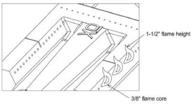
Adjust Main Burner And Air Shutters
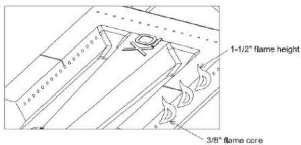
- Light each burner and inspect burners for proper flame appearance
- The best flame appearance is a blue flame with yellow tip
- There is an air shutter found at the end of the main burner Venturi, which can be either opened or closed to make adjustments to the flame's appearance The Air Shutter can be adjusted by loosening the screw and opening the air shutter, then closing it slowly until the flame starts to yellow STOP and turn back 1/16", then tighten the screw. The flame should be blue with yellow tips
CONVERTING YOUR GAS GRILL (CONT'D.)
LOW HEAT ADJUSTMENT
The valves on the grill feature an adjustable low setting. Due to fluctuations in gas pressure, heating value or gas conversion, you may feel it necessary to adjust gas flow in the low position. Do not adjust the infrared rear rotis or optional Sear burner. When doing this adjustment you will be wanting a Blue Flame with a Yellow Tip. Adjust the Valve to obtain this flame
-
Light the burner.
-
Turn the control knob to the lowest setting (all the way counterclockwise). Remove the knob.
-
Insert a small thin flat tipped screw drive into the adjustment screw hole and while viewing the burner flame, adjust toa minimum stable flame. Increase to left and decrease to right.
-
Rear Burner Valve Adjustment:
a. Read Burner Valve must be adjusted by one (1) turn anticlockwise from LP to NG and reversed from NG to LP.

natural_image
Three technical illustrations of mechanical components, shown from different angles (front, side, and top) with no visible text or symbols.Each burner has an air shutter that needs to be adjusted for the correct gas. If you have purchased the grill in the gas type you want then it has been preset at the factory. If you are converting the grill you will need to follow the following steps.
-
Remove each burner.
-
Look at the Silver cover that fits over the burners venturi (part that fits onto the Orifice where gas goes into the burner).
-
Unscrew the small screw that hold the silver part onto the burner.
-
There is a hole that has a N or P on it, slide the silver part until you see the correct gas type.
N=Natural gas
P= Propane gas (bottle gas)
LP to NATURAL GAS


NATURAL GAS to LP
natural_image
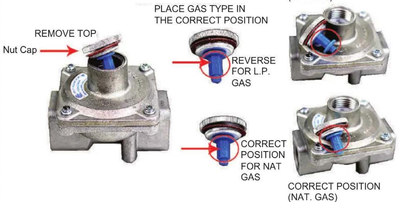
Technical line drawing of a mechanical device with internal components and mounting base (no text or symbols)These instructions describe how to convert a Maxitrol regulator to use either natural gas (NAT-4") or liquid propane gas (LPG-11")
- Carefully remove the top nut cap from the regulator
- Remove Nut Cap and review the small Plastic piece inside the regulator
-
Remove Plastic Piece and turn to the GAS TYPE that you are converting to (see diagram) The plastic piece is clearly market LP or NG.
-
Replace brass top onto the regulator

- Open BBQ hood . DO NOT ATTEMPT TO LIGHT GRILL WITH THE HOOD CLOSED.
- Check to ensure that all burner control knobs are set to OFF.
- Turn on main gas supply.
- Push in and hold knob for 2 seconds while holding the knob in, then turn the knob counterclockwise 1/4 turn to hear the "CLICK" and the burner will ignite. Release knob.
- If burner does not light, turn knob to OFF, wait 5 minutes to allow gas to dissipate, and repeat step 4 above.
- Open hood completely. Do not attempt to light grill with the hood closed.
- Load food onto skewer, and install brackets, motor and skewer onto grill in desired cooking position.
- Check to ensure that all burner control knobs are set to OFF.
- Turn on main gas supply.
- Push in and turn knob 1/4 turn counter clockwise to hear the click to ignite the back burner. When the burner ignites continue to hold in knob for 30 seconds and then release.
- If burner does not light, turn knob to OFF, wait 5 minutes to allow gas to dissipate, and repeat step 5 above.
PREHEATING THE GRILL
Before cooking, always preheat the grill for best results. To preheat the grill, light all main burners and set to HIGH. Close the grill hood and allow to preheat for 10-15 minutes, or until the grill reaches desired temperature.
After preheating, turn off all burners not required, carefully open the hood, and adjust remaining burners to desired temperature.
Do not leave the grill unattended during the preheat cycle or at any time while the grill is in use. Do not allow grill to preheat for prolonged periods of time. Overheating the grill can cause damage to the grill and personal property.
This XO Gas Grill has a "flame out" ignition system located on the rear Burner. This ignition system will automatically switch the gas supply off if the burner is blown out in a windy condition.
Allow the ignition Safety Thermocouple to cool down before trying to relight the back burner.
Note if you are in an extremely windy condition please try and protect the grill from direct wind to the grill front and back.

MANUALLY LIGHTING THE GRILL
- Open the hood and wait five minutes allow any accumulated gas to dissipate.
- Keep your face as far away from the burners as possible.
- Light and insert a long-stem match, holding it near the Lighting Tube on the right side.
- Slowly rotate the burner knob counter-clockwise to the high position.
- If the burner does not light after five seconds, turn the control knobs to the OFF position and wait five minutes until the gas clears before attempting to re-light
- If the burner does not light after several attempts, immediately close all gas valves and consult an authorized service technician.
- To shut off the burners, rotate the knob and turn to OFF.
- It is normal to hear a popping sound when the burners are turned off.

natural_image
Line drawing of a hand operating a mechanical control panel with rotary buttons and dials (no text or symbols)
natural_image
Line drawing of hands operating a vintage kitchen fan with control knobs and a ruler (no text or symbols)
WARNING

Never lean over the grill cooking area while lighting your gas grill. Keep your face and body a safe distance (at least 18 inches) from the front of grill when lighting your grill by match.

WARNING

Do not use standard matches or cigarette lighters to perform match-lighting procedures. Serious burns can occur and lighters can explode.
BURNER TYPE IDENTIFICATION
Your Xgrill comes standard with a Cast Stainless Steel burner. Optional Burners are available and the operation of each burner type varies, so it is important to familiarize yourself with them.

NOT YOUR AVERAGE GRILL NEXT DOOR
Using your new XO Grill
Its time to enjoy your new cooking machine. This is no ordinary grill. It has a combination of Infrared sear burners and Stainless Cast burners. The infrared burner (on the far right) is a favorite of many famous steakhouses. This infrared burner will warm up to a fiery orange/red glow and reach temperatures of up to 1000 degrees in minutes. This is perfect for searing meats and sealing in juices. It can also be adjusted for more gentle cooking.
The durable cast stainless burner coupled with the XO briquette tray system is the all purpose grill and baking area. This burner too can be adjusted from high to low. Allow 15 minutes for the ceramic briquettes to absorb and radiate the heat. Be careful during your first use as the Pro Grade power may be more than you are accustomed to. Dont worry, before long you will love the power and control your XO grill offers.
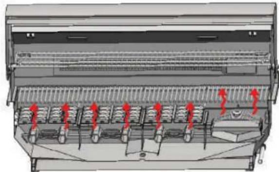
DIRECT COOKING METHOD
Direct cooking involves placing food on grates over direct heat Burners. Use this method for foods that take less than 20 minutes to cook or to sear larger items at the start of the cooking process that will then be indirectly cooked to finish. Place the meat on the preheated surface and leave until they no longer stick. Turning too soon and too often is one of the most common grilling mistakes. Use a meat thermometer to achieve desired doneness and remove items one degree below how you would like to enjoy them, as the resting period before carving or consuming will raise the temperature.
natural_image
Technical diagram of a mechanical device with red arrows indicating directional flow or movement (no text or symbols present)INDIRECT COOKING METHOD
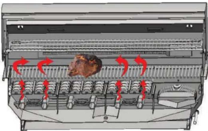
Indirect cooking method is a popular alternative to direct heat grilling. Indirect cooking uses heat from adjacent burners to cook food and, in many cases, reduces the possibility of overcooked or overly browned food. Foods most appropriate for indirect grilling included breads, thicker pieces of chicken or roasts. Indirect cooking involves placing the food on grates where the burners below are not lit and then closing the grill top to create an oven effect. All the items you usually oven-roast can be grilled to perfection using indirect heating. Preheat the burners surrounding the food to be cooked. Use your basting pan below to hold food and add water or marinaid to the pan to prevent the natural juices from burning or evaporating. Place pan on the vaporizers directly under the food above.
natural_image
Diagram of a multi-level kitchen or oven with arrows indicating airflow or movement, showing internal seating arrangement and a central dish (no text or symbols present)USING THE ROTISSERIE
The XO IR rotisserie system consists of three main parts - the motor, the skewer which holds the food, and the infrared rotis back burner. The rotisserie evenly cooks large cuts of meat by turning them continuously in front of a high heat burner. The rotis is capable of turning up to a 25 lb. cut of meat. Make sure the rotis motor is not straining when turning the meat / chicken.
THE MOTOR - The rotisserie motor runs on 110 power that has its own power supply. To power the motor, plug into a 110 power outlet or use a outdoor extension cord. Install the motor onto the grill by sliding it onto the bracket located on the left or right side of the grill. (Bracket is removable and universal for each side)
THE SKEWER - To load the skewer with food, slide one of the meat holders onto the skewer. Push the skewer through the center of the food, then slide the second meat holder onto the skewer. Center the food to be cooked on the skewer then push the meat holders firmly together . Tighten the thumb screws (use pliers if necessary). It may also be necessary to wrap the food with cooking string to secure any loose portions.
WARMING RACK - Remove the warming rack and, if needed, remove the grill racks to gain better clearance. It is normal for the skewer to flex when cooking large foods. Place a cooking pan with water or marinaid beneath the food for basting and to ease cleaning.
THE INFRARED REAR BURNER - The location of the rotis burner makes it more susceptible to strong wind conditions (more so than the main grill burners). For this reason you should avoid operating the rotis cooking during windy conditions. As an added safety feature, the burner is equipped with an automatic safety valve which will not allow gas to flow to the rotis burner if it is not properly lit or goes out.
Rotisserie Available on all models

natural_image
Line drawing of a portable electronic device with control panel and ports (no text or symbols)30" Built in model
natural_image
Line drawing of a portable stove or oven with control panel and side-mounted door (no text or symbols)36" Built in model
natural_image
Line drawing of a portable electronic device with control buttons and a handle (no text or symbols)42" Built in model
natural_image
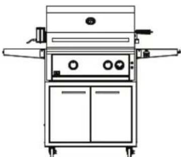
Line drawing of a laboratory apparatus with control panel and side arm (no text or symbols)30" Cart Model
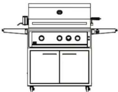
natural_image
Line drawing of a laboratory or industrial machine with control panel and side arm (no text or symbols)36" Cart Model
natural_image
Line drawing of a simple kitchen appliance with control panel and side arm (no text or symbols)42" Cart Model
COOKING TIPS
COOK FOOD TO PROPER TEMPERATURES
Cooking food safely requires that you raise the internal temperature of the meat high enough and for a long enough period of time to kill any food-borne bacteria that may cause illnesses. Color is not the best indicator that food is safe to eat. Use a high-quality probe thermometer to be sure your food is properly cooked. Place the tip of an instant-read thermometer into the center of the thickest part of the food but at least 1/2 inch deep. Read the temperature after about 10 seconds. Follow the temperature guidelines for the type of food you're cooking.
The following guidelines are from the U.S. Food and Drug Administration Center for Food Safety and Applied Nutrition.
| COOK TO INTERNAL TEMP | |||
| Meat And Poultry Medium | Mare Medium Well Done | ||
| Fresh Beef - Medium Rare 145°F | 160°F 170°F | ||
| Ground Turkey, Chicken 165°F | |||
| Ground Veal, Beef, Lamb, Pork | 145°F with 3 minutes of rest and then turn | ||
| Fresh Pork - Medium 160°F 170°F | |||
| Chicken - Whole 165°F | |||
| Turkey - Whole 165°F | |||
| Poultry Breasts, Roast 165°F | |||
| Poultry Thighs, Wings 165°F | |||
| Stuffing (Cooked Alone Or In Bird) | 165°F | ||
| Duck And Goose 180°F | |||
| Fresh Veal - Medium Rare 160°F | |||
| Fresh Lamb - Medium Rare | 145°F 160°F | 170°F | |
| Ham - Fresh (Raw) | 145°F 160°F | 170°F | |
| Ham - Pre-Cooked (Reheat) | 140°F | ||
| SEAFOOD | |||
| Fish | Cook until flesh turns opaque and flakes easily with a fork. | ||
| Shrimp, Lobster, Crab | Cook until shells turn red and flesh becomes pearly opaque. | ||
| Scallops | Should turn milky white or opaque and firm | ||
| Clams, Mussels, Oysters | Cook until shells open. | ||
*The above temperature settings are a guide, the temperatures may vary due to wind and outside ambient temperatures.
BURNER CLEANING AND ADJUSTMENT
Before removing burners ensure the gas supply is off and the knobs are in the "off" position. Make sure the grill has completely cooled before proceeding.
TO REMOVE BURNERS:
Remove the grill racks, vaporizers and zone dividers. Remove the pin holding the burner in place. Grasp the burner, pull it up and slightly to the rear of the unit, so the burner head comes off the brass orifice at the front and remove. Be careful not to upset the air shutter position.
BURNER CLEANING:
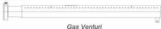
To maximize grill performance, clean the exterior of the burner with a wire brush. Clear stubborn scale with a metal scraper. Clear any clogged ports with a straightened paper clip. Never use a wooden toothpick as it may break off and clog the port. Shake out any debris through the air shutter. Use a flashlight to inspect the burner inlet to ensure it is not blocked. If obstructions can be seen, use a metal wire coat hanger that has been straightened out to clean.
BETTER AIR ADJUSTMENT:
Each grill burner is tested and adjusted at the factory prior to shipment; however, variations in the local gas supply or a conversion from one gas to another may make it necessary to adjust the burners. The flames of the Grill burners should be visually checked, adjusting the air shutter by opening the air shutter and slowly closing it until the flame starts to yellow. STOP and turn back 1/16", and tighten the screw. Flame should be blue with yellow tips when adjusted correctly.

WARNING

It is critical to center every burner on its orifice.

WARNING

For safe operation, make sure the Offices inside the Burner Tubes before using your grill. See figure. is not inside the Burner Tube, lighting the Burner may cause explosion and/or resulting in serious bodily injury and/or property damage.

natural_image
Technical line drawing of a mechanical assembly with no visible text or symbolsGas Valve
Orifice
Burner Tube
Assembly
Orifice
Please Note that the air mixture for LP gas and NG is different. Your gas BBQ will come preset for your gas type. If you find that you are not getting the best flame you can adjust the air shutter and the O2 mix with gas will change the flame. The flame coming from your burner is extremely important. If the flame is not correct you will be able to adjust the flame as described in the section below.

WARNING

Spiders and small insects can spin webs and nest in the grill burner ventures which can lead to a gas flow obstruction resulting in a fire in and around the burner tubes. This type of "FLASHBACK FIRE" can cause serious grill damage and create an unsafe operating condition for the user.
To reduce the chance of FLASHBACK FIRE you must inspect and clean the ventures at least twice a year in summer and fall or whenever spiders are active in your area, and if your grill has not been used for an extended period of time.
Remove the pin from the rear of each Main Burner using needle-nose pliers. Carefully lift each Burner up and away from the Gas VaneuGrifice. Check and clean Burner/V Tubes for insects and insect nests. A clogged tube can lead to a fire beneath the grill.
FOR CLEANING, REFER TO METHODS 1-3 BELOW:
METHOD 1: Bend a stiff wire or wire coat hanger into a small hook as shown and run the hook through the Burner Tube and inside the Burner several times to remove debris.
METHOD 2: Use a bottle brush with a flexible handle and run the brush through the Burner Tube and inside the Burner several times to remove any debris.
METHOD 3: Use an air hose to force air through each Burner Tube. The forced air should pass debris or obstructions through the Burner and out the Ports.

natural_image
Simple line drawing of a handle with a curved handle (no text or symbols)To Clean Burner Tube, Insert Hook Here
Burner Holes Bracket

WARNING

For safe operation ensure the Gas Valve Assembly Orifice is inside the Burner Tube before using your grill. (See above). If the is not inside the Burner Tube, lighting the Burner may cause explosion and/or resulting in serious bodily injury and/or property damage.

natural_image
Technical line drawing of a syringe or pressure vessel with internal components and no visible text or symbols
A LITTLE TLC
GOES A LONG WAY
Cleaning The Grill
Proper care and maintenance will keep your grill in top operating condition and prolong its life. Follow these cleaning procedures on a timely basis and your grill will stay clean and operate with minimum effort. CAUTION: Be sure your grill is OFF and cool before cleaning.
CLEANING THE COOKING GRIDS - Before initial use, and periodically thereafter, wash your Cooking Grids in a mild soap and warm water solution. You can use a wash cloth or vegetable brush to clean your Cooking Grids.
CLEANING THE FLAME TAMERS - You should periodically wash the Flame Tamers in a soap and warm water solution. Use a vegetable brush to remove stubborn burnt-on cooking residue. Dry the Flame Tamers thoroughly before you reinstall them into the grill.
CLEANING THE GREASE TRA Y - To reduce the chance of fire, the Grease Tray should be visually inspected before each grill use. Remove any grease and wash Grease Tray with a mild soap and warm water solution.
CLEANING THE INSIDE OF THE GRILL LID - Grease can build up on the inside of the Grill lid over time. This grease can drip onto your deck or patio when the lid is opened. Visually inspect the inside of the Grill Lid before each grill use. Remove any grease and wash with a mild soap and warm water solution.
ROUTINE CLEANING OF THE GRILL INTERIOR - Burning-off excess food after every cookout will keep it ready for instant use. However, at least every 6 months you must give the entire grill a thorough cleaning to minimize your risk of grease fire and keep the grill in top shape.
FOLLOW THESE STEPS:
- Turn all Control Knobs to the full OFF position. Turn the LP gas tank valve to the full OFF position or turn off NAT gas supply.
- Remove and clean the Vaporizers, Cooking Grids, Warming Rack, Zone Dividers and Grill Burners as above.
- Scrape out and brush the inside and bottom of the grill with a scraper and fiber pad or nylon brush and wash with a mild soap and warm water solution. Rinse thoroughly and let dry.
- Check each Orifice for obstruction.
- Replace the Burners and adjust the Gas Collector Box. The edge of the collector box should be overlapping the Burner Port.
- Replace Burner, F1ZoneTamer dividers and cooking grills.
- Reconnect the gas source and observe the Burner flame for correct operation.
NOTE: Keep Outdoor cooking appliance area clear and free from combustible materials, gasoline and other flammable vapors and liquids. Keeping the ventilation opening(s) of the cylinder enclosure free and clear from debris.
CLEANING YOUR GRILL (CONT.)
CLEANING EXTERIOR STAINLESS STEEL SURFACES:
Routine care and maintenance is required to preserve the appearance and corrosion resistance of stainless steel. The fact is stainless steel can corrode, rust and discolor under certain conditions. Rust is caused when regular steel particles in the atmosphere become attached to the stainless steel surface. Steel particles can also become attached to your grill if you use steel wool or stiff wire brushes to clean the grill instead of non-abrasive cloth, sponge or nylon cleaning tools. In coastal areas rust pits can develop on stainless surfaces that cannot be fully removed. Bleach and other chlorine based solutions used for household and pool cleaning can also cause corrosion to stainless steel. Weathering, extreme heat, smoke from cooking and machine oils used in the manufacturing process of stainless steel can cause stainless steel to turn tan in color. Although there are many factors which can affect the surface appearance of stainless steel, they do not affect the integrity of the steel or the performance of the grill.
TO HELP MAINTAIN THE FINISH OF STAINLESS STEEL FOLLOW THESE CLEANING PROCEDURES FOR THE BEST RESULTS:
- After every use (after your grill has cooled down), wipe stainless surfaces with a soft, soapy cloth or sponge then rinse with water.
- Be sure to remove all food particles, sauces or marinades from stainless steel because these can be highly acidic and damaging to stainless surfaces. Never use abrasive cleaners, scrubbers or stiff wire brushes of any type on your grill.
- Use a heat resistant Stainless Steel Cleaner and rub or wipe in the direction of the stainless steel grain or polish lines. Do not polish against the grain.
LIGHT BULB REPLACEMENT
DO NOT TOUCH THE GLASS OF THE NEW REPLACEMENT BULB.
Replace The Bulb
Replacement bulbs are halogen, 12 volt, 10W max, T3 type with a G4 bi-pin, and are readily available at most stores. The glass cover is held in place by two spring tension tabs. The bulbs are easily removable without the use of tools.
Simply grasp the glass lens at the outer corners, near the front tension clips and push the lens back.
Then, swing the lens down and pull it loose. You may have to loosen the screw to remove the lens.
Avoid touching the glass of a new bulb. Halogen bulbs are very sensitive to the oils found in human skin. Touching the bulbs may shorten their life. Pull the bulb straight out from the socket without twisting. Hold the bulb using a paper towel or other cloth and gently press it straight into the socket. The glass cover should be gently snapped back into place.
natural_image
3D rendering of a mechanical device with colored components and mounting holes (no visible text or symbols)
natural_image
Interior view of a stainless steel industrial machine with metal grating and ventilation grilles, showing red arrows pointing to structural elements (no text or symbols visible)WE'VE GOT YOUR BACK
XO Limited Warranty
WARRANTY TERMS FOR XO - RESIDENTIAL USE ONLY.
XO Stainless Steel Gas Grills & Gas Burners
XO warranties this XO stainless steel gas grill to be free from defects at the time of purchase and for the periods specified below. The grill must be installed by a qualified technician and must be maintained and operated safely, in accordance with the instructions in the owner's manual. This warranty applies to the original purchaser only and is not transferable. All warranty repairs must be accomplished by a qualified gas appliance technician.
Limited Lifetime Warranty
XO warrants the stainless steel cast main burners and fabricated stainless steel housing, to be free from defects in materials and workmanship under normal residential use for the lifetime of the product. This warranty excludes discoloration, surface scratches, weather and atmospheric related staining, and minor surface rust and oxidation which are normal conditions and are to be expected with any outdoor product. The actual part will be repaired or replaced, free of charge, with the owner paying for all other costs including labor, shipping and handling.
FIVE YEAR LIMITED WARRANTY
XO warrants the briquette trays, stainless steel grates, drip pans and gas valves to be free from defects in materials and workmanship under normal residential use for a period of five years from the original date of purchase. The actual part will be repaired or replaced, free of charge, with the owner paying for all other costs including labor, installation, shipping and handling charges.
TWO YEAR LIMITED WARRANTY
XO warrants all other grill components to be free from defects in materials and workmanship under normal residential use for a period of two years from the original date of purchase. The actual part will be repaired or replaced, free of charge, with the owner paying for all other costs including labor, installation, shipping and handling charges.
COMMON AREA WARRANTY
A 180 day warranty applies to applications where use of the product extends beyond normal residential use such as bed and breakfast inn, private clubs, multidwelling condos and apartments. The actual part will be repaired or replaced, free of charge, with the owner paying for all other costs including labor, installation, shipping and handling charges. This warranty excludes all commercial locations such as restaurants and food service locations.
WARRANTY LIMITATIONS & EXCLUSIONS
This warranty shall apply only to the products purchased and located in the continental United States and Canada. The warranty coverage begins on the original date of purchase and proof of date of purchase is required. In order to activate the warranty, we require that you register your product online at www.xoappliance.com within 90 days of purchase. This warranty applies only to the original owner and may not be transferred. This warranty does not apply to damages resulting from negligence, alteration, misuse, abuse, accident, natural disaster, loss of electrical power to the product for any reason, improper installation or improper operation, unauthorized adjustments or calibrations, dings, dents, scratches, or damages due to harsh cleaning chemicals. This warranty does not apply to commercial use, or to products with altered or removed serial numbers.XO shall not be liable for incidental, consequential, special or contingent damages resulting from its breach of this written warranty or any implied warranty.
FOR WARRANTY SERVICE & REPLACEMENT PARTS: check the contact & support section of our website xoappliance.com, email us at service@ xoappliance .com or call 1-800-966-8300 24 Eisenhower Parkway, Roseland, NJ 07068
HOW TO ORDER REPAIR PARTS
Parts Not Under Warranty
Parts can be ordered through XO directly.
Warranty Parts
Warranty parts will need a proof of purchase and can be ordered by contacting XO appliances.. Proof of purchase is required for warranty parts.
All parts listed in the Parts List have a Part Number. When ordering parts, first obtain the Model Number and Serial Number from the name plate on your equipment. Then determine the Part Number and the Description of each part from the following illustration and part list. Be sure to give all this information . . .
Appliance Model Number ____ Part Description ____
Appliance Serial Number ____ Part Number ____
Type of Gas (Propane or Natural
Do not order bolts, screws, washers or nuts. They are standard hardware items and can be purchased at any local hardware store. Shipments contingent upon strikes, fires and all causes beyond our control.
Your XO Premium Gas Grill is identified by model number, serial number, and gas type. This information is provided on a product identification label located on the left side of the grill and under the grill's drip tray. For your convenience, complete this section for future reference when contacting XO Appliance
CONTACTING XO APPLIANCE DIRECTLY
Before contacting XO Appliance, please make sure you have the following information:
- Model number
- Date of purchase
• Proof of purchase by the original owner - Serial number
The serial number can be located on the rating plate which is located on the left side of the grill or on the pull-out drip tray lighting instructions and also on the underside of the drip tray.

An Applicable 24 Haushwaar Fairway Fornion 6 N23768 Xiaoparkov.com 001961 0000
WARNING: Fuel vector gas or oil-fried appliances and the products of contusion of such link, coniser chemicals known to the State of California to cause cancer, birth defects and/or other reproductive harm. This warning is issued pursuant to California Health & Safety Code, Sec. 25241-6. Handling the breast material on this product exposes you to lead, a chemical known to the state of California to cause cancer, birth defects or other reproductive harm (such home after handling this product).
| MODEL | PRICE SIZE(mm) | GASTYPE | RPT/QUARTERSTOCK |
| XOGHRL33LP | 14 | PROPANE | 2200 |
| BEAR | 11 | PROPANE | 1100 |
| XOGHRL38HG | 2.26 | NATURAL GAS | 2200 |
| BEAR | 1.5 | NATURAL GAS | 1100 |
| XOGHRL38LP | 1.4 | PROPANE | 3300 |
| BEAR | 11 | PROPANE | 1100 |
| XOGHRL38HG | 2.26 | NATURAL GAS | 3300 |
| BEAR | 1.5 | NATURAL GAS | 1100 |
| XOGHRL42LP | 1.4 | PROPANE | 2200 |
| BEAR | 11 | PROPANE | 1100 |
| XOGHRL42HG | 2.26 | NATURAL GAS | 2200 |
| BEAR | 1.5 | NATURAL GAS | 1100 |
SERA#
RATING PLATE
PROpane MODELS :
Do not share a Open LP-gas cylinder under or near the cylinder. Never fil the gas cylinder beyond 10% will change of gas cylinder under or near the cylinder and/or overfilling of the cylinder may cause after reaching a death or venous injury.
CAUTION: A LP gas pressure regulator bar at 11° MC MUST be used with this gel appliance. Turn off LP supply at Cylinder when this appliance is not in use. If closed indoors, beach and leave cylinder outdoors
NATURAL GAS MODELS
A BCG gas press on regulator set at 1" NC MUST be used with this appliance. The regulator supplied must be used with this appliance.
NOTE
Do not place Under any Combustible Surface. Minimum clearance to adjacent combustible construction is 14' from sides & 15' from the back of the load. Always follow all City and Local codes. A Permit may be required and Your local City will provide this permit. Always use a certified professional gas appliance install.
CONFORMS TO:
ANS 253.11-2016/CSA | A-2016 Electrical Requirements: 12/F 60Hz 40V Transformer Only for Installation in a suit in constructed of soe-controllable material. When installed in a combustible material a insulated jacket must be used.

TAKE A MINUTE TO CIRCLE YOUR MODEL ABOVE AND RECORD YOUR SERIAL NUMBER HERE IN CASE YOU NEED IT LATER

XO GRILL PARTS LIST
| ITEM | PART NO. | GRILL SIZE | DESCRIPTION |
| 1 | XDPG033 | ALL | Temperature Gauge |
| 2 | XDPG034 | XO30 | Hood welding-KO30" |
| XDPG034 | XO36 | Hood welding-KO36" | |
| XDPG035 | XO40 | Hood welding-KO40" | |
| 3 | XDPG036 | XO30/42 | Hood spring-KO30/KO3" |
| XDPG037 | XO36 | Hood spring-KO36" | |
| 4 | XDPG038 | XO30 | Hood handle-KO30" |
| XDPG039 | XO36 | Hood handle-KO36" | |
| XDPG040 | XO40 | Hood handle-KO40" | |
| 5 | XDPG041 | XO30 | Ceramic flame tamer-KO30" |
| XDPG042 | XO36 | Ceramic flame tamer-KO36" | |
| XDPG043 | XO40 | Ceramic flame tamer-KO40" | |
| 6 | XDPG044 | XO30/42 | Firebox heat separator-KO30/KO3" |
| XDPG045 | XO36 | Firebox heat separator-KO36" | |
| 7 | XDPG005 | ALL | Rodge |
| 8 | XDPG047 | ALL | Blue LED light |
| 9 | XDPG048 | XO30 | LED assembly- KO 30" |
| XDPG049 | XO36 | LED assembly- KO 36" | |
| XDPG050 | XO40 | LED assembly-KO 42" | |
| 10 | XDPG051 | ALL | Main valve |
| 11 | XDPG052 | ALL | Rear burner valve |
| 12 | XDPG053 | XO30 | Firebox welding-KO30" |
| XDPG054 | XO36 | Firebox welding-KO36" | |
| XDPG055 | XO40 | Firebox welding-KO40" | |
| 13 | XDPG056 | XO30/42 | Firebox vent guard baffle- KO30/KO3" |
| XDPG057 | XO36 | Firebox vent guard baffle- KO36" | |
| 14 | XDPG058 | XO30 | Crashfire panel-KO30" |
| XDPG059 | XO36 | Crashfire panel-KO36" | |
| XDPG060 | XO40 | Crashfire panel-KO40" | |
| 15 | XDPG061 | ALL | Main control knob |
| 16 | XDPG062 | ALL | Rear burner control knob |
| 17 | XDPG063 | ALL | Knob bezel |
| 18 | XDPG064 | XO30 | Control panel welding-KO30" |
| XDPG065 | XO36 | Control panel welding-KO36" | |
| XDPG066 | XO40 | Control panel welding-KO40" | |
| 19 | XDPG067 | ALL | Switch |
| 20 | XDPG068 | ALL | Transformer valve |
| 21 | XDPG069 | ALL | BMW transformer |
| 22 | XDPG070 | XO30 | Gas Manifold-KO30" |
| XDPG071 | XO36 | Gas Manifold-KO36" | |
| XDPG072 | XO40 | Gas Manifold-KO40" | |
| 23 | XDPG073 | XO30 | Burner bracket-KO30" |
| XDPG074 | XO36 | Burner bracket-KO36" | |
| XDPG075 | XO40 | Burner bracket-KO40" | |
| 24 | XDPG076 | XO30 | Drip tray-KO30" |
| XDPG077 | XO36 | Drip tray-KO36" | |
| XDPG078 | XO40 | Drip tray-KO40" | |
| 25 | XDPG079 | ALL | Igniter stick |
| 27 | XDPG080 | XO30 | Warming rack-KO30" |
| XDPG081 | XO36 | Warming rack-KO36" | |
| XDPG082 | XO40 | Warming rack-KO40" | |
| 28 | XDPG083 | ALL | Igniter |
| ITEM | PART NO. | GRILL SIZE | DESCRIPTION |
| 29 | KDPG084 | ALL | Rear burner thermocouple |
| KDPG045 | KD30 | Rear burner thermocouple | |
| 30 | KDPG083 | ALL | Rear burner lightbar cover |
| 31 | KDPG086 | ALL | Roller |
| 32 | KDPG087 | KD30 | Rear burner-XO30" |
| KDPG088 | KD36 | Rear burner-XO36" | |
| KDPG089 | KD42 | Rear burner-XO42" | |
| 33 | KDPG090 | KD30 | crossfire tube-XO30" |
| KDPG091 | KD36 | crossfire tube-XO36" | |
| KDPG092 | KD42 | crossfire tube-XO42" | |
| 34 | KDPG145 | KD36 | Hood support base left-XO36" |
| KDPG093 | KD36 | Hood support base right-XO36" | |
| KDPG148 | XD30/42 | Hood support base left-KD30/42" | |
| KDPG150 | XD30/42 | Hood support base right-XO30/42" | |
| 35 | KDPG094 | ALL | Larger rubber bumper |
| 36 | KDPG095 | ALL | Screw for spring |
| 37 | KDPG096 | KD30 | Stainless steel flaxline-XO30" |
| KDPG097 | XD36/42 | Stainless steel flaxline-XO36/42" | |
| 38 | KDPG098 | ALL | Right hood light housing |
| 39 | KDPG199 | KD30/36 | Left hood light-XO30/36" |
| KDPG100 | KD42 | Left hood light-XO42" | |
| 40 | KDPG101 | KD30 | Fimbox back cover-XO30" |
| KDPG102 | KD36 | Fimbox back cover-XO36" | |
| KDPG103 | KD42 | Fimbox back cover-XO42" | |
| 41 | KDPG104 | KD30 | Verr guard for back cover-XO30" |
| KDPG105 | KD36 | Verr guard for back cover-XO36" | |
| KDPG106 | KD42 | Verr guard for back cover-XO42" | |
| 42 | KDPG107 | ALL | Upper Warming rack bracket |
| KDPG108 | KD30 | Back Warming rack bracket-XO30" | |
| KDPG109 | XD36/42 | Back Warming rack bracket-XO42" | |
| KDPG110 | ALL | Side Warming rack bracket | |
| 43 | KOCHREURNER | ALL | IR burner |
| 44 | KDPG1124 | KD30 | Stainless steel cast burner-XO30" |
| KDPG1128 | XD36/42 | Stainless steel cast burner-XO36/42" | |
| 45 | KDPG113 | KD30 | Cooking grill-XO30" |
| KDPG114 | KD36 | Cooking grill-XO36" | |
| KDPG115 | KD42 | Cooking grill-XO42" | |
| 46 | KDPG116 | ALL | Motor |
| 47 | KDPG117 | ALL | Motor bracket |
| 48 | KDPG118 | ALL | Rottaserle fork |
| 49 | KDPG119 | ALL | Screw for Rottaserle fork |
| 50 | KDPG120 | KD30 | Ratio rod-XO30" |
| KDPG121 | KD36 | Ratio rod-XO36" | |
| KDPG122 | KD42 | Ratio rod-XO42" | |
| 51 | KDPG123 | ALL | Counter balance |
| 52 | KDPG124 | ALL | Lock nut |
| 53 | KDPG125 | ALL | Black Handle for Rottaserle Rod |
| 54 | KDPG157 | ALL | Roller Bearing Assembly |
| 55 | KDPG158 | KD30 | Rod Holdem-XO30" |
| KDPG159 | XD36/42 | Rod Holdem-XO36/42" | |
| 56 | KDPG164 | ALL | Handle Standoff |
PARTS DIAGRAM
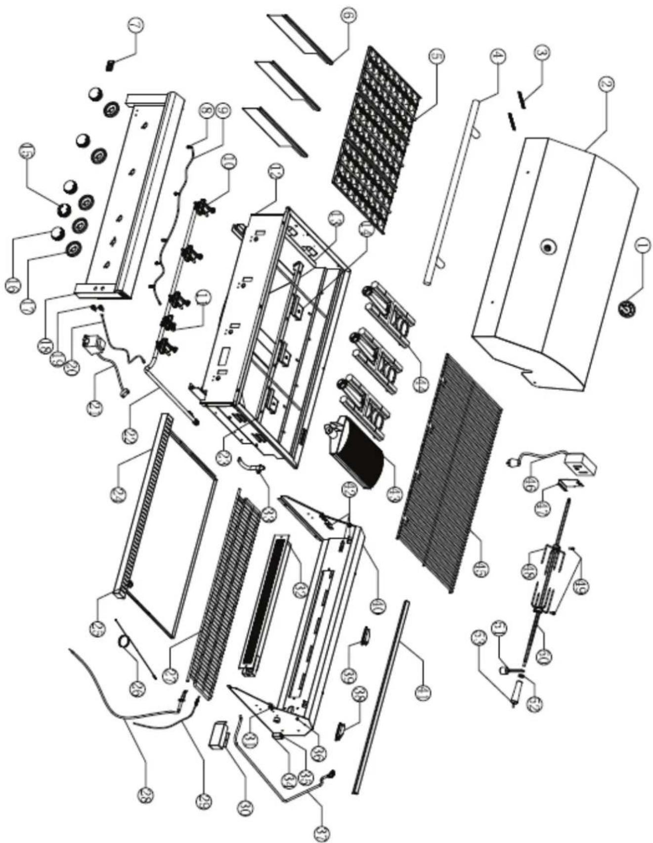
DATE OF INSTALLATION:
DATE OF SERVICE:
WORK PERFORMED:
DATE OF SERVICE:
WORK PERFORMED:
DATE OF SERVICE:
WORK PERFORMED:
DATE OF SERVICE:
WORK PERFORMED:
DATE OF SERVICE:
WORK PERFORMED:
DATE OF SERVICE:
WORK PERFORMED:
DATE OF SERVICE:
WORK PERFORMED:
DATE OF SERVICE:
WORK PERFORMED:
DATE OF SERVICE:
WORK PERFORMED:
DATE OF SERVICE:
WORK PERFORMED:

XO manufactures a complete line of accessories to compliment your new grill.
All Weather Covers to protect your investment.
Power and Side Burners
Outdoor Ventilation Hoods
Access Doors and Drawers
Trash Centers
BarPro Cocktail Centers and Sinks
Factory Assembled Designer Islands
Outdoor Refrigerators and Gourmet Ice Makers
Wood-Fired Pizza Ovens
Fire Pits
See the entire collection of XO Outdoor products at www.xoappliance.com and while you are there checkout XO's complete line of luxury appliances.
Undercounter Beverage Centers
Undercounter Wine Coolers
Designer Kitchen Ventilation
Built-In Microwaves
Waster Disposals
AND THANKS,
FOR CHOOSING

Xo

natural_image
Outdoor patio scene with a modern bench, wooden table, chairs, and potted pavement (no visible text or symbols)NOW WE ARE COOKING

1-800-966-8300
Visit our web site at www.xoappliance.com


- EVERYTHING YOU NEED TO KNOW ABOUT
- YOUR
- GAS GRILL
- CARE & USE / INSTALLATION
- Installation, Care And Use Of Your XO Professional Cooking Product
- DANGER
- WARNING
- FOR OUT DOOR USE ONLY
- NOTE TO INSTALLER
- WHERE THINGS ARE
- MEET YOUR XO
- UNIQUE FEATURES AND BENEFITS
- PLEASE READ AND FOLLOW ALL SAFETY INSTRUCTIONS
- OVERALL
- GRILL DIMENSIONS
- CONTROL
- IDENTIFICATION
- IGNITION POSITION:
- YOUR SAFETY MATTERS
- NOTICE: COMMONWEALTH OF MASSACHUSETTS
- WARNING! CALIFORNIA PROPOSITION 65
- GRILL LOCATION
- WHERE IS THE WIND COMING FROM?
- HOW LONG IS YOUR GAS RUN GOING TO BE?
- CHECK THE BBQ IS LEVEL?
- USING YOUR GRILL IN WINDY CONDITIONS:
- BUT THERE ARE A FEW THINGS YOU CAN DO TO FURTHER PREVENT THE POSSIBILITY OF IMPROPER HEAT BUILDUP:
- CLEARANCE TO COMBUSTIBLE CONSTRUCTION:
- OUTDOOR RATED EXHAUST HOODS
- BUILT IN GRILL DIMENSIONS
- ISLAND VENTING
- INSULATED SLEEVE INSTALLATION INSTRUCTIONS
- SLEEVE INSTALLATION
- GRILL INSTALLATION
- FINISHING
- INSULATED
- BUILT-IN SLEEVE
- ELECTRICAL REQUIREMENTS AND HOOK-UP
- WARNING! ELECTRICAL GROUNDING
- CALIFORNIA PROPOSITION 65
- CAUTION
- WIRING SCHEMATICS
- SAFETY NOTICE
- GAS REQUIREMENTS AND HOOK-UP
- LP GAS MODEL ONLY - TYPE 1 CONNECTION WITH REGULATOR AND HOSE TO YOUR LP GAS TANK.
- CHECK ALL CONNECTIONS FOR LP GAS LEAKS.
- FOLLOW THESE THREE STEPS:
- GAS REQUIREMENTS AND HOOK-UP (CONT'D.)
- NATURAL GAS CONNECTION KIT INCLUDED WITH GAS GRILL
- CONNECTING TO A PERMANENTLY PLUMBED GAS LINE
- GAS SAFETY INSTRUCTIONS
- CHECK ALL CONNECTIONS FOR GAS LEAKS
- IMPORTANT GRILLING SAFETY INFORMATION
- CONVERTING YOUR GAS GRILL
- HOW DO I CONVERT MY GRILL GAS TYPE?
- Rear Burner
- Adjust Main Burner And Air Shutters
- CONVERTING YOUR GAS GRILL (CONT'D.)
- LOW HEAT ADJUSTMENT
- PREHEATING THE GRILL
- MANUALLY LIGHTING THE GRILL
- BURNER TYPE IDENTIFICATION
- NOT YOUR AVERAGE GRILL NEXT DOOR
- Using your new XO Grill
- DIRECT COOKING METHOD
- INDIRECT COOKING METHOD
- USING THE ROTISSERIE
- COOKING TIPS
- COOK FOOD TO PROPER TEMPERATURES
- BURNER CLEANING AND ADJUSTMENT
- TO REMOVE BURNERS:
- BURNER CLEANING:
- BETTER AIR ADJUSTMENT:
- FOR CLEANING, REFER TO METHODS 1-3 BELOW:
- A LITTLE TLC
- GOES A LONG WAY
- Cleaning The Grill
- FOLLOW THESE STEPS:
- CLEANING YOUR GRILL (CONT.)
- CLEANING EXTERIOR STAINLESS STEEL SURFACES:
- TO HELP MAINTAIN THE FINISH OF STAINLESS STEEL FOLLOW THESE CLEANING PROCEDURES FOR THE BEST RESULTS:
- LIGHT BULB REPLACEMENT
- Replace The Bulb
- WE'VE GOT YOUR BACK
- XO Limited Warranty
- Limited Lifetime Warranty
- FIVE YEAR LIMITED WARRANTY
- TWO YEAR LIMITED WARRANTY
- COMMON AREA WARRANTY
- WARRANTY LIMITATIONS & EXCLUSIONS
- HOW TO ORDER REPAIR PARTS
- Warranty Parts
- CONTACTING XO APPLIANCE DIRECTLY
- Before contacting XO Appliance, please make sure you have the following information:
- RATING PLATE
- PROpane MODELS :
- NATURAL GAS MODELS
- NOTE
- CONFORMS TO:
- PARTS DIAGRAM
- Xo
- NOW WE ARE COOKING
Brand : XO
Model : XOGRILL30L
Category : Barbecue