
4072-12QC-PO-SS - Water dispenser Perlick - Free user manual and instructions
Find the device manual for free 4072-12QC-PO-SS Perlick in PDF.

| Product Type | T-Pipe or H-Pipe Beverage Tower |
| Brand | Perlick |
| Model | 4072-12QC-PO-SS |
| Material | Stainless Steel |
| Mounting Hole Diameter | 3.5 inches |
| Maximum Coolant Line Distance | 100 feet (between Refrigeration Deck and Glycol Bath) |
| Refrigeration Deck Clearance | Minimum 6 inches on louvered ends |
| Glycol Bath Reservoir Capacity | Approximately 12 gallons |
| Coolant Solution | Perlick Approved #63299-1 (pre-mixed) |
| Voltage | 115V (typical, dedicated circuit required) |
| Warranty | Void if ventilation inadequate |
| Weight | Approx 25 lbs |
| Dimensions | Varies by configuration; typical height ~28 inches |
| Installation Requirements | 3.5 in. hole, support brackets mandatory, sealant if needed |
| Safety Notice | California Prop 65: Contains chemicals known to cause cancer |
Frequently Asked Questions - 4072-12QC-PO-SS Perlick
User questions about 4072-12QC-PO-SS Perlick
0 question about this device. Answer the ones you know or ask your own.
Ask a new question about this device
Download the instructions for your Water dispenser in PDF format for free! Find your manual 4072-12QC-PO-SS - Perlick and take your electronic device back in hand. On this page are published all the documents necessary for the use of your device. 4072-12QC-PO-SS by Perlick.
USER MANUAL 4072-12QC-PO-SS Perlick
Installation Instructions
Avenue T-Pipe and H-Pipe Towers
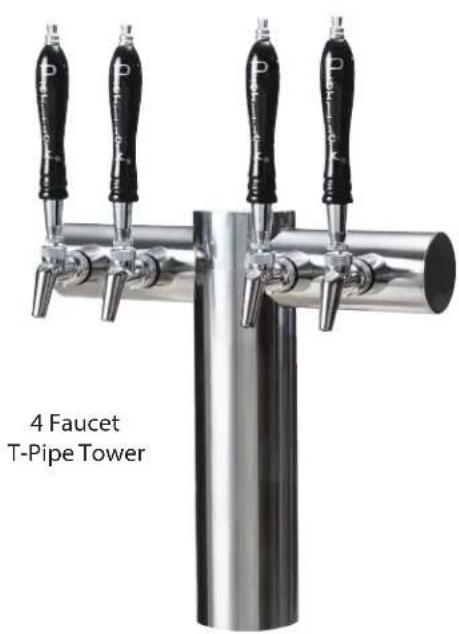
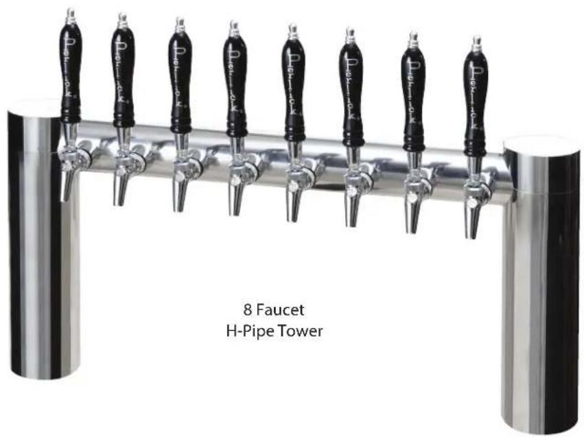
Installation of T-Pipe and H-Pipe Towers
Included with Tower:
T-Pipe Tower (L) or H-Pipe Tower (R)
(Faucets and tap handles shown are not included)
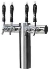
natural_image
Close-up of a stainless steel trowel with three black handles (no text or symbols visible)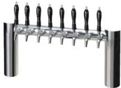
natural_image
Close-up of a stainless steel stand with multiple black-handled handles (no text or symbols visible)Other Parts Needed for Installation: The parts required will vary depending on the installation.
| PART NO. DESCRIPTION | |
| 63486 Coolant Line Connector Kit | |
| C33037 Clamp, SS - Stepless |
Parts Bag Included with Tower:
Parts bag contents include –
Black Poly-tape Clear poly-tape
natural_image
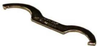
Close-up of a metallic curved tool or knob with a curved handle and central hole (no visible text or symbols)Spanner wrench
Preparing for Installation:
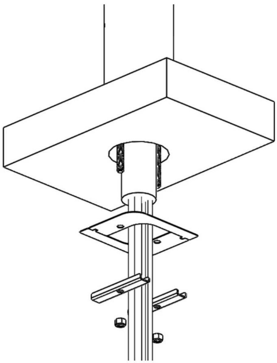
- The towers are shipped with the Mounting hardware installed, which includes two flat Mounting Plates (hockey stick shaped), two Hold Down Brackets (U channel shaped), and two Hex Nuts.
- Remove the two Hex Nuts and all brackets.
Hold Down Bracket Hex Nut Mounting Plate
(Figure 1)
natural_image
Close-up of a mechanical device with transparent container and black component, no visible text or symbols(Figure 2)
- Drill one (1) 3.5" diameter hole per base. Position tower centered over hole. Note: Do not drill extra holes for threaded rods and trunk housing. (See Figure 2a)
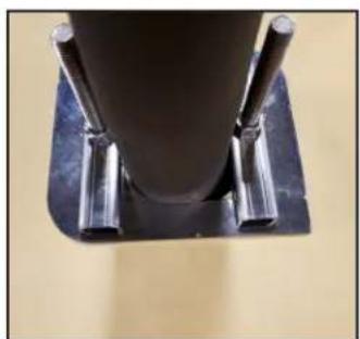
(Figure 2: View from underneath)
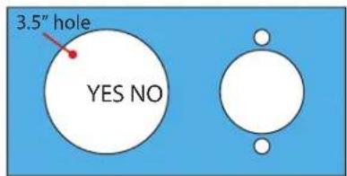
(Figure 2a)
(Figure 3)
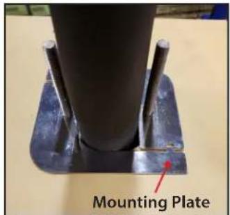
- Install mounting plates. Note: If underside of countertop is steel, skip to step 3
(Figure 3: View from underneath)
(Figure 4)
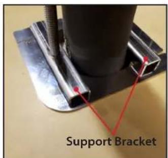
- Install support brackets. Note: Support brackets must be used in all installations of tower. (See Figure 4a)
(Figure 4: View from underneath)
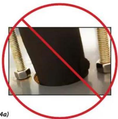
natural_image
Close-up of a black rubber head with two metallic bolts and a red prohibition symbol (no text or symbols on the main subject)(Figure 4a) Do not mount without support brackets
natural_image
Close-up of a cylindrical mechanical component mounted on a dark base with two metallic pins (no visible text or symbols)(Figure 5)
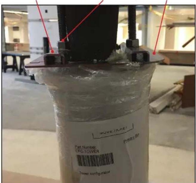
- Install nuts. Note: Interlock mounting plates before tightening the nuts. After hand tightening the nuts with the mounting plates flush and interlocked, tighten nuts between one and one and-a-half turns with wrench.
(Figure 5: View from underneath)
natural_image
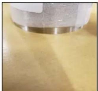
Close-up of a metallic cylindrical object on a yellow surface (no visible text or symbols)(Figure 6)
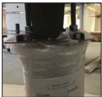
- After tightening the nuts on the bottom side, make sure tower is securely fastened by pushing and pulling on the outermost faucet like an aggressive bar tender may push or pull. Note: Depending on bar top material, sealant may be required.
(Figure 6: View from top - protective shipping material still on the tower)
CONNECTING REFRIGERATION DECK AND GLYCOL BATH
- Determine the ideal placement of the Refrigeration Deck and Glycol Bath. It is recommended that the distance between the Refrigeration Deck and Glycol Bath does not exceed 100 feet (contact the factory if longer distances are required). NOTE: If the Refrigerated Deck is to be located on top of the walk-in cooler or in an enclosed area, it is imperative that proper ventilation is provided to prevent system failure due to overheating. Inadequate ventilation will void warranty.
- Place the Refrigeration Deck on a level surface and fasten in place using included mounting tabs if needed on Deck base. REMINDER: Allow a minimum of six inches of clearance on louvered ends of the cabinet for proper airflow. Allow accessibility room on the top of the cabinet as well as the front of the cabinet for serviceability.
- Mark Coolant Connector Lines for feed line and return line. Use compressed air to blow through the lines to identify.
- Route Coolant Connector Line Set from Refrigeration Deck to Glycol Bath.
- Remove top cover and front panel on Refrigeration Deck. Remove Access Hole Shroud (if equipped)
- Make coolant line connections and clamp using included Oetikers (Inlet fitting is located on the outside of the cabinet, outlet fitting is located inside the cabinet). Insulate the glycol lines completely to avoid condensation and unnecessary heat gain. (Ensure that the feed line is connected to the inlet fitting and the return line to the outlet fitting).
- Connect Low Voltage wires to the two wires with bell connectors on them [(1) Black wire, (1) White wire]. See Wiring Diagrams (pages 11-13) for proper connections.
- Connect Refrigeration Deck to proper power source. Permanently connected units should be wired per the wiring diagram and circuit should be sized according to the I.D. plate's electrical specifications. The circuit should be sized in accordance with the electrical requirements of the unit as well as in compliance with all National and Local codes (codes may require a separate disconnect for these units). NOTE: Electrical circuit should be a dedicated circuit for use only with the Refrigeration Deck.
- Make Coolant Line connections on Glycol Bath, one to pump outlet, the other to bath return tube and clamp using included Oetikers (Coolant Connector feed line).
- Remove the top front panel on the bath and the electrical box front cover.
- Connect low voltage wires to the low voltage transformer secondary wires with bell connectors (Blue and Yellow wires).
- Ensure power switches for the pump motor(s) are in the OFF position. (Check transformer to ensure the leads are connected to the low voltage side of the transformer). Make the electrical connections per the wiring diagram. The circuit should be sized in accordance with the electrical requirements of the unit as well as in compliance with all National and Local Codes (codes may require a separate disconnect for these units). NOTE: Electrical circuit should be a dedicated circuit for use only with the Glycol Bath.
• Re-install Electrical Box Cover.
CONNECTING TO FLASH CHILL COILS
If the Glycol Bath includes flash chill coils, then follow these instructions for proper connections:
- Locate Glycol Bath in-line with convenient point along the trunk housings to splice into the product lines and glycol feed line within the trunk housing (this location could be inside the walk-in cooler, immediately outside the walk-in cooler or anyplace along the trunk housing up to the point of connection to the dispensing head).
- To make the proper connections, Flash Chill Connector kit 68455 is required. Using instructions included with kit 68455 make the necessary connections for each product tube and coolant line.
GLYCOL BATH INSIDE WALK-IN COOLER
- Connect and clamp incoming product lines to inlet of flash chill tube(s). Connect and clamp outgoing product lines to outlet of flash chill tube(s). Using included coolant loop coils from kit 68455, (pick the correct size based on the number of flash chill tubes) hook up to glycol lines (see kit instructions 68455-INS).
- Tape and insulate the coolant loop and outgoing product tubes to prevent condensation on heat gain into the newly flash chilled product lines. The product lines should be taped to the coolant lines and then combined should be fully insulated to the trunk housing insulation.
GLYCOL BATH LOCATED ALONG THE TRUNK HOUSING.
In this scenario, the pump to maintain the product temperature within the trunk housing is going to go from the pump outlet to the flash chill coolant loop, then from the flash chill coolant loop to the trunk housing coolant line to the dispensing head, then back through the trunk housing to the walk-in cooler and finally back to the Glycol Bath.
- If the trunk housing is located along the path of the trunk housing, then the trunk housing must be spliced, similarly to dropping product lines at a dispensing head, except in this case all the product lines are being dropped to the flash chill coils along with the feed line of the glycol circuit.
- Once all coolant and product connections are made using the included oetiker clamps, product lines are securely taped to the coolant lines and then all product lines and coolant lines are insulated using the included insulation to prevent condensation and heat leak.
CONNECTING TO A TRUNK HOUSING
- Inspect pump outlet port for cleanliness
- Cut supplied coolant tubing (#54588) to required length to reach from Glycol Bath to Trunk Housing connection point.
- Cut tubular insulation (#C12700) in half and install over previously cut coolant tubing.
• Take Oetiker clamps (#54871-210) and install over coolant tubing ends. - Push coolant lines, one each over pump outlet barbed fitting and bath return port on bath cover.
- Position Oetikers over tube ends and clamp securely.
- Slide tubular insulation tightly against connection points. Use insulation tape as necessary to ensure an air tight seal to prevent excessive heat gain or condensation problems.
- Drill a 3-1/2" diameter hole in walk-in cooler to accommodate coolant lines.
- Slide large insulation (#57478) over remaining coolant tubing exposed to warm air conditions including inside walk-in cooler from Bath to Trunk Housing connection point. Seal and tape all seams to prevent excessive heat gain or condensation problems.
- Slide coolant lines though 3-1/2" hole previously cut in walk-in cooler wall.
- Position Trunk Housing coolant lines and Coolant Connector kit lines in horizontal position, to alleviate condensation runoff into Trunk Housing.
- Cut Trunk Housing coolant lines with tubing cutter to ensure clean burr-free ends.
- Install Oetikers over plastic coolant lines coming from bath. Slide lines over coolant lines from trunk housing and clamp Oetikers.
- Seal around hole where insulated coolant lines pass through walk-in cooler wall to ensure an air tight seal to prevent walk-in cooler problems as well as condensation.
CONNECTING TRUNK HOUSING COOLANT LINES TO DISPENSING HEAD
- Position the trunk housing so that beverage lines can be connected with a minimum cutting.
- Split trunk housing approximately 12 inches from the end to allow working room for the connections.
- Cut and deburr copper coolant lines coming from trunk housing and dispensing head. Stagger the lengths.
- Connect trunk housing coolant lines to dispensing head coolant lines using installation kit included with dispensing head connecting kit. Ensure that clamps are properly installed to guarantee a leak-free connection.
- Make product line connections from trunk housing to dispensing head.
- Pressurize lines to ensure that they are leak-free.
- After system start-up, tape product lines to coolant lines and re-insulate product lines, gluing and taping all the seams.
SYSTEM START-UP
Use only Perlick Approved Coolant Solution (#63299-1), all other solutions and mixtures will void the Perlick warranty. The Coolant Solution has been pre-mixed for optimum performance and wear protection. The Glycol Bath resevoir holds approximately 12 gallons of solution. It takes approximately 1 gallon of Coolant Solution to fill every 60 feet of Perlick Trunk Housing.
- Never operate the circulating pumps without coolant in the resevoir.
- Fill resevoir with Perlick Coolant Solution.
- Turn Pump Switch #1 to the ON position. Coolant solution level will begin to drop in resevoir. It is filling the Coolant Connector Line set between the Glycol Bath and the Refrigeration Deck.
- Continue adding Perlick Coolant Solution until no air bubbles are apparent from the Coolant return line. NOTE: Never allow for the Coolant level in the resevoir to drop below the pump inlet tube. Allowing the level to drop below the inlet will allow air into the lines.
- Check glycol line connections at both the Bath and the Refrigeration Deck for leaks.
- Refrigeration Deck should be running if the glycol is above the set point temperature.
- Turn on power to each individual pump motor and fill all other glycol lines, adding glycol to bath as needed to maintain proper glycol level within the reservoir. Check all other glycol connections for leaks.
-
Re-install Refrigeration Deck front panel and Top Cover.
-
Fill reservoir to within 2 inches of the top edge of the tank. Watch return lines for additional air bubbles as this may signify additional Coolant Solution may need to be added.
- Thoroughly check all field connection points for leaks.
- Monitor Glycol Bath Temperature read-out to ensure Refrigeration Deck is working properly. Dependent on length of trunk housing run(s) and surrounding ambient conditions, these factors will determine how long it takes for the system to cut-out on the temperature control. The control is factory programmed to cut-out at 30°F with a hysteresis of 2°F. The control has also been programmed to prevent short cycling and requires one minute of off time before it will restart.
• Re-install Glycol Bath Cover.
! WARNING: California Prop 65 Notice
These products may expose you to chemicals including Chromium, which are known to the state of California to cause cancer and birth defects or other reproductive harm. For more information on whether a product in this list contains these chemicals, please refer to the specific product page at perlick.com. Or to find out more about Prop 65, go to P65Warnings.ca.gov.
natural_image
Technical line drawing of a mechanical assembly with a central column and mounting base (no text or symbols)
Form No. Z2609
Rev. 10.25.22
- Installation Instructions
- Avenue T-Pipe and H-Pipe Towers
- Installation of T-Pipe and H-Pipe Towers
- Included with Tower:
- T-Pipe Tower (L) or H-Pipe Tower (R)
- Parts Bag Included with Tower:
- Preparing for Installation:
- CONNECTING REFRIGERATION DECK AND GLYCOL BATH
- CONNECTING TO FLASH CHILL COILS
- GLYCOL BATH INSIDE WALK-IN COOLER
- GLYCOL BATH LOCATED ALONG THE TRUNK HOUSING.
- CONNECTING TO A TRUNK HOUSING
- CONNECTING TRUNK HOUSING COOLANT LINES TO DISPENSING HEAD
- SYSTEM START-UP
- ! WARNING: California Prop 65 Notice
Brand : Perlick
Model : 4072-12QC-PO-SS
Category : Water dispenser