
Redbox RB-TGHDX - Professional Audio Sonifex - Free user manual and instructions
Find the device manual for free Redbox RB-TGHDX Sonifex in PDF.

| Product Type | Multi-Channel High Definition Tone Generator |
| Model | Redbox RB-TGHDX |
| Analog Outputs | 8 x XLR 3-pin male (balanced, impedance <50Ω) |
| Digital Outputs | 4 x XLR 3-pin male (balanced, 110Ω AES/EBU) |
| Number of Channels | 2, 4, 6, or 8 selectable |
| Sample Rates | 32, 44.1, 48, 88.2, 96, 176.4, 192 kHz |
| Sample Width | 16-bit or 24-bit |
| Audio Line-Up | 0 dBu to +24 dBu in 1 dB steps ref FSD |
| Built-in Sequences | EBU R49, GLITS, BLITS stereo & channel ID, Phase, User |
| Sync Inputs | Word Clock (BNC, 50Ω), optional AES/EBU, analogue/digital video sync boards |
| Remote Control | Serial RS232 (D-sub 9) and remote port (D-sub 25, 17 inputs, 7 tally outputs) |
| Dimensions (Raw) | 48 cm (W) x 15.8 cm (D) x 4.3 cm (H) (1U) |
| Weight (Net) | 1.3 kg |
| Power Supply | Filtered IEC, 85-264 VAC, 47-63 Hz, 60W peak, 30W average |
| Fuse Rating | 2A, 5 x 20 mm, anti-surge |
| Safety Class | Class I (must be earthed) |
| Operating Environment | Temperature 0-50°C, avoid moisture, dust, vibration |
| Cleaning | Use a dry, lint-free cloth; do not use liquids or sprays |
| User Serviceable Parts | None; refer to qualified personnel for repairs |
Frequently Asked Questions - Redbox RB-TGHDX Sonifex
User questions about Redbox RB-TGHDX Sonifex
0 question about this device. Answer the ones you know or ask your own.
Ask a new question about this device
Download the instructions for your Professional Audio in PDF format for free! Find your manual Redbox RB-TGHDX - Sonifex and take your electronic device back in hand. On this page are published all the documents necessary for the use of your device. Redbox RB-TGHDX by Sonifex.
USER MANUAL Redbox RB-TGHDX Sonifex
RB-SS10 10 Way Stereo Analogue Source Selector/Mixer
RB-DSS10 10 Way Stereo Digital Source Selector
RB-PMX4 10 Input, 4 Output Analogue Pre-set Mixer (1U)
RB-DMX4 4 x 4 Channel Digital Audio Mixer/Router (1U)
RB-SSML1 Mic/Line Source Selector with Compressor/Limiter
RB-OA3 3 Studio On-Air Switcher
RB-OA3R Remote Switch Panel For RB-OA3
RB-OA3C Expansion Unit Cable Kit for RB-OA3
RB-MM1 Mix-Minus Generator
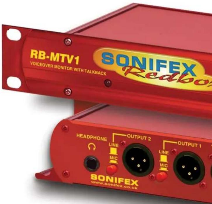
RB-MTV1 Contribution Voiceover Monitor with Talkback
RB-IPE IP Extender for GPIO & Analogue Control Signals
RB-TGHDB Multi-Channel High Definition Tone Generator
RB-TGHDX Multi-Channel High Definition Tone Generator
Manufacturers of audio & video products for radio & TV broadcasters
SONIFEX
Redbox Handbook 6
For the latest Sonifex handbook information please visit the Sonifex website at www.sonifex.co.uk
Redbox User Handbook No 6
Revision 3.05, March 2020
©Sonifex Ltd, 2020
All Rights Reserved
Stock Code: 30-345
Artwork: AW10840
Sonifex Ltd, 61, Station Road, Irthlingborough,
Northants, NN9 5QE, England.
Tel: +44 (0)1933 650 700
Fax: +44 (0)1933 650 726
Email: sales@sonifex.co.uk
Website: https://www.sonifex.co.uk
Information in this document is subject to change without notice and does not represent a commitment on the part of the vendor. Sonifex Ltd shall not be liable for any loss or damage whatsoever arising from the use of information or any error contained in this manual.
No part of this manual may be reproduced or transmitted in any form or by any means, electronic or mechanical, including photocopying, recording, information storage and retrieval systems, for any purpose other than the purchaser's personal use, without the express written permission of Sonifex Ltd. Unless otherwise noted, all names of companies, products and persons contained herein are part of a completely fictitious adaptation and are designed solely to document the use of Sonifex product.
Made in the UK by SONIFEX
Contents
Contents
Product Warranty - 2 Year Extended ii
Sonifex Warranty & Liability Terms & Conditions ii
-
Definitions ii
-
Warranty ii
Unpacking Your Product iii
Repairs & Returns iv
€Conformity iv
Safety & Installation of Mains Operated Equipment iv
Voltage Setting Checks iv
Fuse Rating iv
Power Cable & Connection iv
WEEE Directive v
Atmosphere/Environment v
Fitting Redboxes v
1 RB-SS10 10 Way Stereo Analogue Source Selector/Mixer 1
Introduction 1
System Block Diagram 2
Front Panel Indicators & Controls 2
Rear Panel Connections and Operation 4
RB-SS10 Remote Start I/O 5
Technical Specifications RB-SS10 8
2 RB-DSS10 10 Way Stereo Digital Source Selector 9
Introduction 9
System Block Diagram 10
Front Panel Indicators & Controls 10
Rear Panel Connections and Operation 12
Technical Specifications RB-DSS10 15
3 RB-PMX4 10 Input, 4 Output Analogue Preset Mixer 16
Introduction 16
System Block Diagram 17
Rear Panel Connections and Operation 18
Front Panel Controls 18
Technical Specifications RB-PMX4 19
4 RB-DMX4 4 x 4 Channel Digital Audio Mixer/Router 20
Introduction 20
Front Panel Controls and Indicators 22
Rear Panel DIPSwitch Controls 24
Boot Mode (DIPSwitch 12) 26
Applications of Use 26
Rear Panel Connectors 27
Serial Port Control 28
Serial Interface Commands and Responses 29
SCi for RB-DMX4 31
Status Page 31
Control Page 32
Miscellaneous Page 33
Updating The Firmware 33
Technical Specification For RB-DMX4 34
5 RB-SSML1 Mic/Line Source Selector with
Compressor Limiter 36
Introduction 36
System Block Diagram 37
Rear Panel Connections 38
Front Panel Controls 40
Technical Specifications RB-SSML1 41
6 RB-OA3 3 Studio On-Air Switcher 42
Introduction 42
System Block Diagram 43
Rear Panel Connections and Operation 44
Configuring for Operation 45
Studio Expansion 46
Bus Expansion 47
Studio & Bus (4 Unit) Expansion 48
Indications – How The LEDS Are Used 50
Operational Modes 50
Rear Panel Connections & Operation 52
Connecting an RB-PD2 Profanity Delay to the RB-OA3 Switcher 56
Technical Specifications RB-OA3 56
7 RB-OA3R Remote Switch Panel For RB-OA3 58
Introduction 58
Technical Specifications RB-OA3R 59
8 RB-OA3C Expansion Unit Cable Kit For RB-OA3 60
Introduction 60
Technical Specifications RB-OA3C 60
9 RB-MM1 Mix Minus Generator 61
Introduction 61
Contents & Figures
System Block Diagram 61
Front Panel Indicator 62
Rear Panel Connections and Operation 62
Stereo Inputs From Mixer Main Output 62
Input From Mixer Telephone Fader 62
Output Null Adjustments (LF and Full-Band) 62
Band Pass Filter Switch 62
Output to Telephone Balance Unit (TBU) 62
Output Level Adjustment 63
Operation of the RB-MM1 63
Technical Specifications RB-MM1 63
10 RB-MTV1 Contribution Voiceover Monitor With Talkback 65
Introduction 65
System Block Diagram 66
Front Panel Controls & Indicators 67
Rear Panel Connections & Operation 68
Technical Specification For RB-MTV1 72
11 RB-IPE IP Extender for GPIO & Analogue Control Signals 73
Introduction 73
Controls & Indicators
Front Panel Controls and Indicators
Rear Panel 75
Input & Output Port Specifications
RB-IPE Inputs 76
RB-IPE Outputs 77
Relay General Purpose Outputs 77
Ethernet Interface Commands and Responses 78
Identification and Network Commands:
Communication Sequencing: 78
Port Configuration Commands: 80
RB-IPE Webserver 83
Updating the RB-IPE
Technical Specification For RB-IPE
12 RB-TGHD(B&X) Multi-Channel High Definition Tone
Generator 85
Introduction 85
Front Panel Controls & Indicators 86
Sequence Details 89
Rear Panel Connections & Operation 93
Serial Interface Commands & Responses Protocol 95
Serial Data Format 95
RB-TGHD SCi Remote Control Software 97
Installing the Optional Sync Boards 100
Opening the RB-TGHD 100
Technical Specification RB-TGHD (B & X) 101
Figures
Fig A: RB-RK1Small Redbox Front Rack-mount Kit. v
Fig B: RB-RK2 Small Redbox Rear Rack-mount Kit. vi
Fig C: RB-RK3 Large Redbox Rear Rack-mount Kit. vi
Fig 1-1: RB-SS10 Front Panel 1
Fig 1-2: RB-SS10 System Block Diagram 2
Fig 1-3: RB-SS10 Front Panel 2
Fig 1-4: RB-SS10 Rear Panel 4
Fig 1-5: Analogue Audio Inputs Pin Connections 5
Fig 1-6: Remote Start Pin Connections 6
Fig 1-7: Connection Example 6
Fig 1-8: Remote Select/Switch Input Connections 6
Fig 1-9: Connection Example 6
Fig 1-10: Status Output Pin Connections 7
Fig 1-11: Connection Example 7
Fig 2-1: RB-DSS10 Front Panel 9
Fig 2-2: RB-DSS10 System Block Diagram 10
Fig 2-3: RB-DSS10 Front Panel 10
Fig 2-4: RB-DSS10 Rear Panel 12
Fig 2-5: Digital Audio Inputs and S/PDIF Output
Pin Connections 13
Fig 2-6: Remote Start Pin Connections. 13
Fig 2-7: Connection Example 14
Fig 2-8: Remote Select/Switch Input Connections 14
Fig 2-9: Status Output Pin Connections 14
Fig 2-10: Connection Example 15
Fig 3-1: RB-PMX4 Front Panel 16
Fig 3-2: RB-PMX4 Block Diagram 17
Fig 3-3: RB-PMX4 Rear Panel 18
Fig 3-4: RB-PMX4 Front Panel Controls 18
Figures
Fig 4-1: RB-DMX4 Front Panel 20
Fig 4-2: RB-DMX4 System Block Diagram 21
Fig 4-3: RB-DMX4 Front Panel Controls and Indicators 22
Fig 4-4: RB-DMX4 Front Panel DIPSwitches 22
Fig 4-5: RB-DMX4 INPUT 1 & 2 Select Button 22
Fig 4-6: RB-DMX4 INPUT Gain Pots 23
Fig 4-7: RB-DMX4 MONITOR Button 23
Fig 4-8: RB-DMX4 Serial Control Indicator LED 24
Fig 4-9: RB-DMX4 Headphone Output & Level Control 24
Fig 4-10: RB-DMX4 Rear Panel DIPSwitch Block 24
Fig 4-11: RB-DMX4 Rear Panel 27
Fig 4-12: Serial Port Default Settings 28
Fig 4-13: Status Page 31
Fig 4-14: Control Page 32
Fig 4-15: Miscellaneous Page 33
Fig 5-1: RB-SSML1 Front Panel 36
Fig 5-2: RB-SSML1 Block Diagram 37
Fig 5-3: RB-SSML1 Rear Panel. 38
Fig 5-4: DIP Switch to Control Mic & Meter Features 39
Fig 5-5: RB-SSML1 Front Panel 40
Fig 6-1: RB-OA3 Front Panel 42
Fig 6-2: RB-OA3 System Block Diagram 43
Fig 6-3: RB-OA3 Rear Panel 44
Fig 6-4: RB-OA3 Unit Identity Definitions 44
Fig 6-5: RB-OA3 Unit Identity Reset Settings 45
Fig 6-6: RB-OA3 Studio Expansion Diagram 46
Fig 6-7: RB-OA3 Bus Expansion Diagram 47
Fig 6-8: RB-OA3 Studio & Bus Expansion Diagram 48
Fig 6-9: RB-OA3 Multiple RB-OA3 Expansion Diagram 49
Fig 6-10: Offer & Accept Button Operation 52
Fig 6-11: RB-OA3 LSO Expansion Connector Definitions 52
Fig 6-12: RB-OA3 LSO Expansion Connector Details 52
Fig 6-13: RB-OA3 Mix Input Connector Definitions 53
Fig 6-14: RB-OA3 Mix Input Connector Details 53
Fig 6-15: RB-OA3 Transmission I/O Connector Definitions 54
Fig 6-16: RB-OA3 Transmission Outputs Connector Details 54
Fig 6-17: RB-OA3 Studio 1-3 Audio Connector Definitions 54
Fig 6-18: RB-OA3 Studio 1-3 Audio Connector Details 55
Fig 6-19: RB-OA3 Studio 1-3 Control Connector Definitions 55
Fig 6-20: RB-OA3 Switch & Lamp Control Details 55
Fig 6-21: RB-OA3 Profanity Delay Control Connector Definitions56
Fig 6-22: RB-OA3 Profanity Delay Control Connector Details 56
Fig 7-1: RB-OA3R Front Panel 58
Fig 7-2: RB-OA3R Rear Panel 58
Fig 7-3: RB-OA3R Control Function Indication Colour 58
Fig 7-4: RB-OA3R Pin Out Definitions 59
Fig 7-5: RB-OA3R Pin Out Positions 59
Fig 9-1: RB-MM1 Front Panel. 61
Fig 9-2: RB-MM1 System Block Diagram 61
Fig 9-3: RB-MM1 Rear Panel. 62
Fig 10-1: RB-MTV1 Front Panel 65
Fig 10-2: RB-MTV1 Block Diagram 66
Fig 10-3: MIC Button 67
Fig 10-4: LED Meter 67
Fig 10-5: Limit LED 67
Fig 10-6: TALK Button 67
Fig 10-7: Headphone Level Controls 67
Fig 10-8: RB-MTV1 Rear Panel Connections 68
Table 10-1: Rear Panel DIPSwitch Configuration Settings 70
Fig 10-9: Underside of RB-MTV1 Showing Headphone Channel Mix DIPSwitches 71
Table 10-2: Underside DIPSwitch Settings For Headphone Channel Mix Options 71
Fig 11-1: RB-IPE Front Panel 73
Fig 11-2: RB-IPE Block Diagram 74
Fig 11-3: Front Panel Controls and Indicators 75
Fig 11-4: RB-IPE Rear Panel 75
Fig 11-5: Isolated General Purpose Inputs 76
Fig 11-6: Active Low General Purpose Inputs 76
Fig 11-7: Analogue Control Voltage Inputs 76
Fig 11-8: Relay General Purpose Outputs 77
Fig 11-9: Opto-Isolated General Purpose Outputs 77
Fig 11-10: Analogue Control Voltage Inputs 78
Fig 11-11: Screen shot of the RB-IPE Webserver home page 83
Figures
Fig 12-1: RB-TGHDX Front Panel 85
Fig 12-2: Channel Active LEDs 86
Fig 12-3: Channels Button & LEDs 86
Fig 12-4: Sequence Mode Button & LEDs 86
Fig 12-5: Sequence Button & LEDs 86
Table 12-1: Valid Sequences For Channel Configurations 87
Table 12-2: Sequence Restart Button Action 87
Table 12-3: Digital Sample Rate Settings 87
Fig 12-6: Sequence Loop Button & LEDs 87
Fig 12-7: DIPSwitch Settings 87
Table 12-4: Synchronization Mode Settings 88
Table 12-5: Digital Sample Width Settings 88
Table 12-6: Audio Line-Up Settings 88
Fig 12-8: RB-TGHDX Rear Panel 93
Fig 12-9: RB-TGHDB Rear Panel 93
Table 12-7: Remote Inputs 94
Table 12-8: Remote Outputs 94
Fig 12-10: SCi Launcher 97
Fig 12-11: SCi Device Discovery Panel 97
Fig 12-12: SCi Launcher Loaded 97
Fig 12-13: SCi Main Control Screen 98
Fig 12-14: SCi User Sequence Screen 98
Fig 12-15: SCi Misc Screen 99
Table 12-9: Firmware Upgrade Status LED 100
SONIFEX
Register Online for an Extended 2 Year Warranty
As standard, Sonifex products are supplied with a 1 year back to base warranty.
If you register the product online, you can increase your product warranty to 2 years and we can also keep you informed of any product design improvements or modifications.
Product: ____ Serial No: ____
To register your product, please go online to www.sonifex.co.uk/register
Warranty
Product Warranty - 2 Year Extended
As standard, Sonifex products are supplied with a 1 year back to base warranty. In order to register the date of purchase and so that we can keep you informed of any product design improvements or modifications, it is important to complete the warranty registration online. Additionally, if you register the product on the Sonifex website, you can increase your product warranty to 2 years. Go to the Sonifex website at: https://www.sonifex.co.uk/technical/register/index.asp to apply for your 2 year warranty.
Sonifex Warranty & Liability Terms & Conditions
1. Definitions
'the Company' means Sonifex Ltd and where relevant includes companies within the same group of companies as Sonifex Limited.
'the Goods' means the goods or any part thereof supplied by the Company and where relevant includes: work carried out by the Company on items supplied by the Purchaser; services supplied by the Company; and software supplied by the Company.
'the Purchaser' means the person or organisation who buys or has agreed to buy the Goods.
'the Price' means the Price of the Goods and any other charges incurred by the Company in the supply of the Goods.
'the Warranty Term' is the length of the product warranty which is usually 12 months from the date of despatch; except when the product has been registered at the Sonifex website when the Warranty Term is 24 months from the date of despatch.
'the Contract' means the quotation, these Conditions of Sale and any other document incorporated in a contract between the Company and the Purchaser.
This is the entire Contract between the parties relating to the subject matter hereof and may not be changed or terminated except in writing in accordance with the provisions of this Contract. A reference to the consent, acknowledgement, authority or agreement of the Company means in writing and only by a director of the Company.
2. Warranty
a. The Company agrees to repair or (at its discretion) replace Goods which are found to be defective (fair wear and tear excepted) and which are returned to the Company within the Warranty Term provided that each of the following are satisfied:
i. notification of any defect is given to the Company immediately upon its becoming apparent to the Purchaser;
ii. the Goods have only been operated under normal operating conditions and have only been subject to normal use (and in particular the Goods must have been correctly connected and must not have been subject to high voltage or to ionising radiation and must not have been used contrary to the Company's technical recommendations);
iii. the Goods are returned to the Company's premises at the Purchaser's expense;
iv. any Goods or parts of Goods replaced shall become the property of the Company;
v. no work whatsoever (other than normal and proper maintenance) has been carried out to the Goods or any part of the Goods without the Company's prior written consent;
vi. the defect has not arisen from a design made, furnished or specified by the Purchaser;
Warranty
vii. the Goods have been assembled or incorporated into other goods only in accordance with any instructions issued by the Company;
viii. the defect has not arisen from a design modified by the Purchaser;
ix. the defect has not arisen from an item manufactured by a person other than the Company. In respect of any item manufactured by a person other than the Company, the Purchaser shall only be entitled to the benefit of any warranty or guarantee provided by such manufacturer to the Company.
b. In respect of computer software supplied by the Company the Company does not warrant that the use of the software will be uninterrupted or error free.
c. The Company accepts liability:
(i) for death or personal injury to the extent that it results from the negligence of the Company, its employees (whilst in the course of their employment) or its agents (in the course of the agency);
(ii) for any breach by the Company of any statutory undertaking as to title, quiet possession and freedom from encumbrance.
d. Subject to conditions (a) and (c) from the time of despatch of the Goods from the Company's premises the Purchaser shall be responsible for any defect in the Goods or loss, damage, nuisance or interference whatsoever consequential economic or otherwise or wastage of material resulting from or caused by or to the Goods. In particular the Company shall not be liable for any loss of profits or other economic losses. The Company accordingly excludes all liability for the same.
e. At the request and expense of the Purchaser the Company will test the Goods to ascertain performance levels and provide a report of the results of that test. The report will be accurate at the time of the test,
to the best of the belief and knowledge of the Company, and the Company accepts no liability in respect of its accuracy beyond that set out in Condition (a).
f. Subject to Condition (e) no representation, condition, warranty or other term, express or implied (by statute or otherwise) is given by the Company that the Goods are of any particular quality or standard or will enable the Purchaser to attain any particular performance or result, or will be suitable for any particular purpose or use under specific conditions or will provide any particular capacity, notwithstanding that the requirement for such performance, result or capacity or that such particular purpose or conditions may have been known (or ought to have been known) to the Company, its employees or agents.
g. (i) To the extent that the Company is held legally liable to the Purchaser for any single breach of contract, tort, representation or other act or default, the Company's liability for the same shall not exceed the price of the Goods.
(ii) The restriction of liability in Condition (g)(i) shall not apply to any liability accepted by the Seller in Condition (c).
h. Where the Goods are sold under a consumer transaction (as defined by the Consumer Transactions (Restrictions on Statements) Order 1976) the statutory rights of the Purchaser are not affected by these Conditions of Sale.
Unpacking Your Product
Each product is shipped in protective packaging and should be inspected for damage before use. If there is any transit damage take pictures of the product packaging and notify the carrier immediately with all the relevant details of the shipment. Packing materials should be kept for inspection and also for if the product needs to be returned.
CE Conformity
The product is shipped with the following equipment so please check to ensure that you have all of the items below. If anything is missing, please contact the supplier of your equipment immediately.
Item
Quantity
Product unit 1
IEC mains lead fitted with moulded mains plug 1
Handbook and warranty card 1
If you require a different power lead, please let us know when ordering the product.
Repairs & Returns
Please contact Sonifex or your supplier if you have any problems with your Sonifex product. Email technical.support@sonifex.co.uk for the repair/ upgrade/returns procedure, or for support & questions regarding the product operation.
CE Conformity
The products in this manual comply with the essential requirements of the relevant European health, safety and environmental protection legislation.
The technical justification file for this product is available at Sonifex Ltd.
The declaration of conformity can be found at:
https://www.sonifex.co.uk/declarations
Safety & Installation of Mains Operated Equipment
There are no user serviceable parts inside the equipment. If you should ever need to look inside the unit, always disconnect the mains supply before removing the equipment covers. The cover is connected to earth by means of the fixing screws. It is essential to maintain this earth/ground connection to ensure a safe operating environment and provide electromagnetic shielding.
Voltage Setting Checks
Ensure that the machine operating voltage is correct for your mains power supply by checking the box in which your product was supplied. The voltage is shown on the box label. The available voltage settings are 115V, or 230V. Please note that all products are either switchable between 115V and 230V, or have a universal power supply.
Fuse Rating
The product is supplied with a single fuse in the live conducting path of the mains power input. For reasons of safety it is important that the correct rating and type of fuse is used. Incorrectly rated fuses could present a possible fire hazard, under equipment fault conditions. The active fuse is fitted on the outside rear panel of the unit.
Power Cable & Connection
An IEC power connector is supplied with the product which has a moulded plug attached.
The mains plug or IEC power connector is used as the disconnect device. The mains plug and IEC power connector shall remain readily operable to disconnect the apparatus in case of a fault or emergency.
The mains lead is automatically configured for the country that the product is being sent to, from one of:
Territory Voltage IEC Lead Type Image
| UK & Middle East 230V UK 3 pin to IEC lead | (4HZX) | |
| Europe 230V | European Schuko round 2 pin to IEC lead | |
| USA, Canada and South America | 115V 3 flat pin to IEC lead | |
| Australia & New Zealand | 230V Australasian 3 flat pin to IEC lead | |
Connect the equipment in accordance with the connection details and before applying power to the unit, check that the machine has the correct operating voltage for your mains power supply.
This apparatus is of a class I construction. It must be connected to a mains socket outlet with a protective earthing connection.
Important note: If there is an earth/ground terminal on the rear panel of the product then it must be connected to Earth.
WEEE Directive

The Waste Electrical and Electronic Equipment (WEEE) Directive was agreed on 13 February 2003, along with the related Directive 2002/95/EC on Restrictions of the use of certain Hazardous Substances in electrical and electronic
equipment (RoHS). The Waste Electrical and Electronic Equipment Directive (WEEE) aims to minimise the impacts of electrical and electronic equipment on the environment during their life times and when they become waste. All products manufactured by Sonifex Ltd have the WEEE directive label placed on the case. Sonifex Ltd will be happy to give you information about local organisations that can reprocess the product when it reaches its "end of use", or alternatively all products that have reached "end of use" can be returned to Sonifex and will be reprocessed correctly free of charge.
Atmosphere/Environment
This apparatus should be installed in an area that is not subject to excessive temperature variation (<0°C, >50°C), moisture, dust or vibration.
This apparatus shall not be exposed to dripping or splashing, and no objects filled with water, such as vases shall be placed on the apparatus.
Fitting Redboxes
Redboxes can be fixed to the underside of a desk, or other surfaces using 4.2mm holes in the sides and fixed with 2 x M4 screws or 2 x No. 6 countersink wood screws.


Fig A: RB-RK1Small Redbox Front Rack-mount Kit.
Safety & Installation
They can also be rack-mounted, with either the front, or rear of the Redbox positioned at the front of the rack (Note: this product is front rack-mounted as standard):
Front Mounting Redboxes: For rack mounting smaller (28cm) units the optional RB-RK1 (Red) or RB-RK1B (Black) kit can be used (which include 4 off M6 panel fixing screws).
Rear Mounting a Redbox: For rear panel mounting you can use either the RB-RK2 (in this case), or RB-RK3, depending on the size of your Redbox.
RK2

Fig B: RB-RK2 Small Redbox Rear Rack-mount Kit.
RK3

Fig C: RB-RK3 Large Redbox Rear Rack-mount Kit.
vi
1 RB-SS10 10 Way Stereo Analogue Source Selector/Mixer
Introduction

Fig 1-1: RB-SS10 Front Panel
The RB-SS10 10 Way Stereo Analogue Source Selector/Mixer is a 1U rack-mount unit that produces a stereo analogue audio output from 10 selectable stereo analogue sources. There are 10 illuminated front panel push buttons, which select and indicate the current channel selection. The selection and indication is also available through a remote connector on the rear panel. To stop accidental front panel selection there is a remote input to inhibit the front panel buttons.
As well as being able to act as a source select module, the RB-SS10 can act as a mixer, by enabling the mix mode (using the remote input).
The gain for left and right inputs can be individually adjusted by using the preset potentiometers on the front panel.
As well as routing the selected audio signal, the unit will also route a remote signal input through the remote connector to the selected input source, for starting external audio equipment such as a CD player.
The front panel headphone output has its own volume control, which is independent of the level adjustment for the main outputs, and has a maximum output level of +12dBu. The volume control can be made to also alter the output level of the main XLR outputs by using a switch on the rear panel to enable/disable this feature.
There is a designation strip on the front panel, useful for giving the buttons a meaningful description. The strip covers the input gain controls so that once configured, they can't easily be altered – ideal for installation work.
The LED on the front panel is used to indicate that power is present on the unit.
1 Mixers, Source Selectors & Switchers - RB-SS10
System Block Diagram
![graph TD A["Inputs"] --> B["Input Gain Stage"] B --> C["Analogue Switches"] C --> D["MCU"] D --> E["Push Button Switches"] E --> F["Status Outputs"] G["Audio Inputs 1-2"] --> H["Remote Start I/O"] H --> I["Remote Start In"] I --> J["MCU"] J --> K["Back to MCU"] L["Audio Inputs 3-6"] --> M["Back to M…](/content/2026/06/1225749/images/46ffcb5439effca7ff6bdedce6026cb60ae6b7c0d18092746a01351c83127e4a.jpg)
Fig 1-2: RB-SS10 System Block Diagram
Front Panel Indicators & Controls
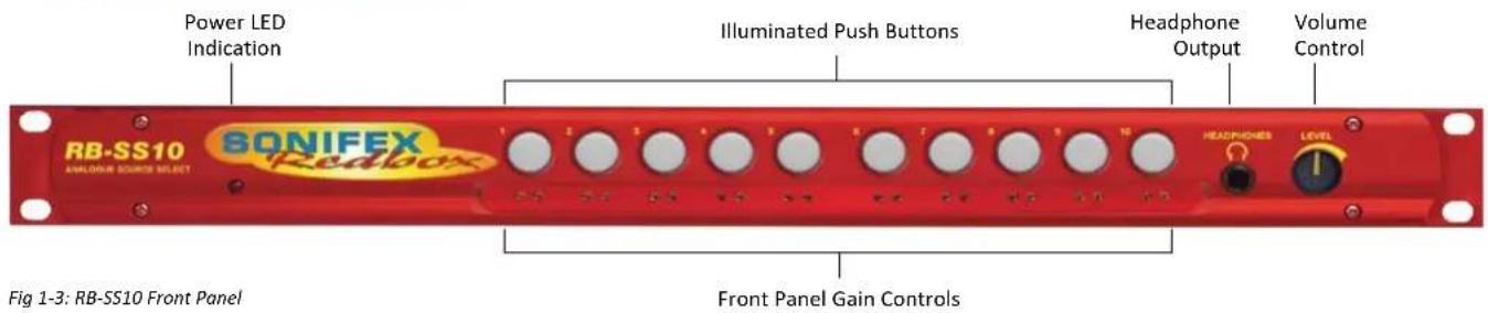
Illuminated Push Buttons
The front panel contains 10 illuminated push buttons, used for selecting an analogue source. The push button illuminates when the input is selected. The status of pin 12 on the remote connector determines whether the unit is in the selector mode, or the mix mode. When pin 12 is connected to 0V, mix mode is enabled.
In selector mode, one push of a button will select the desired analogue stereo source and pushing the button again will turn it off.
In mix mode, each button you press will select that source allowing multiple sources to be mixed to a single output. Pressing the button again will switch off a source.
There is also a remote input to inhibit the front panel switches. When the front panel inhibit is active, pressing the front panel switches has no effect on the current channel selection.
Front Panel Gain Controls
The input gain can be individually adjusted for left and right channels through pre-set potentiometers which are accessible through the front panel. The gain range of the input is -8dBu to +20dBu.
Headphone Output
The front panel headphone output is a 1/4 " stereo jack socket and is designed to drive 150mW into 32Ω - 600Ω professional headphones.
Volume Control
The volume control is used to alter the headphone output. It can also be used to alter the main XLR output levels by using a rear panel switch to enable/disable the control.
Additional Modes
An option to set the unit in different modes of operation is available and can be configured at anytime while the unit is powered.
There are currently three modes of operation: Alternate mode, Latched
mode and Protected Alternate mode: -
Alternate Mode
In this mode the channels are selected and deselected by a press of the button, as described previously.
Latched Mode
In this mode the selected channel is active only while the button is pressed. As soon as button is released the channel becomes inactive.
Protected Alternate Mode
Operates in a similar manner to the Alternate mode, but a channel cannot be turned off unless switching to another input or while operating in mix-mode and there is more than one channel active. In other words, there will always be a channel routed to the output. NOTE: after setting this mode there will be no channel selected.
Configuring the Additional Modes
While the unit is powered, hold down the input 10 button and press the input 5 button five times. Once completed, the input 10 button will start to flash and the first 3 input buttons will display the current operating mode (as shown below). To change the mode, simply press the input 10 and the buttons will indicate the newly selected mode. Once the required operating mode has been set the unit will restart within five seconds from the last button press.
| INPUT 1 button on = Alternate mode | |
| INPUT 2 button on = Latched mode | |
| INPUT 3 button on = Protected Alternate mode |
1 Mixers, Source Selectors & Switchers - RB-SS10
Rear Panel Connections and Operation

Fig 1-4: RB-SS10 Rear Panel
Inputs
Two of the stereo analogue audio inputs are on XLR-3 pin sockets (female) so that they can be used for equipment which you may want to plug/unplug on a regular basis and isn't pre-wired, e.g. portable recorders.
The four XLR-3 inputs can take balanced professional levels, or unbalanced by using the front panel gain controls, and by connecting the non-phase to the signal ground. They have the following connections:
Pin 1: Screen
Pin 2: Phase
Pin 3: Non-phase
Outputs
The two XLR 3 pin outputs are electronically balanced, and can be wired unbalanced. Each output is individually buffered so that a short circuit on one output will not affect the others. They have the following connections:
Pin 1: Screen
Pin 2: Phase
Pin 3: Non-phase
Altering the Master Output Level
When the Output Level Control push-switch is Enabled (pushed in) on the rear panel, it changes the functionality of the front panel volume control to also alter the level of the master output, as well as the headphone volume.
RB-SS10 Additional Audio Input Connectors
There are 2 off 25 way D-type sockets (female) used for the remaining audio inputs.
The INPUTS 3 - 6 (upper) connector contains analogue inputs 3-6, and the INPUTS 7 - 10 (lower) connector contains analogue inputs 7-10.
| Pin No. I/O INPUTS 3 - 6 connector INPUTS 7 – 10 connector | |
| Pin 1 | Audio input 3 left phase Audio input 7 left | phase |
| Pin 2 - Chassis ground Chassis ground | |
| Pin 3 | Audio input 3 right non-phase | Audio input 7 right non-phase |
| Pin 4 | Audio input 4 left phase Audio input 8 left | phase |
| Pin 5 - Chassis ground Chassis ground | |
| Pin 6 | Audio input 4 right non-phase | Audio input 8 right non-phase |
| Pin 7 | Audio input 5 left phase Audio input 9 left phase | phase |
| Pin 8 - Chassis ground Chassis ground | |
| Pin 9 | Audio input 5 right non-phase | Audio input 9 right non-phase |
| Pin 10 | Audio input 6 left phase Audio input 10 left phase | left phase |
| Pin 11 - Chassis ground Chassis ground | |
| Pin 12 | Audio input 6 right non-phase | Audio input 10 right non-phase |
| Pin 13 - No internal connection No internal connection | |
| Pin 14 | Audio input 3 left non-phase | Audio input 7 left non-phase |
| Pin 15 | Audio input 3 right phase Audio input 7 right phase | |
| Pin 16 - Chassis ground Chassis ground | |
| Pin 17 | Audio input 4 left non-phase | Audio input 8 left non-phase |
| Pin 18 | Audio input 4 right phase Audio input 8 right phase | |
| Pin 19 - Chassis ground Chassis ground | |
| Pin 20 | Audio input 5 left non-phase | Audio input 9 left non-phase |
| Pin 21 | Audio input 5 right phase Audio input 9 right phase | |
| Pin 22 - Chassis ground Chassis ground | |
| Pin 23 | Audio input 6 left non-phase | Audio input 10 left non-phase |
| Pin 24 | Audio input 6 right phase | Audio input 10 right phase |
| Pin 25 - Chassis ground Chassis ground | |
Fig 1-5: Analogue Audio Inputs Pin Connections
RB-SS10 Remote Start I/O
This 25 way D-type plug (male) connector contains the remote start input connection and the corresponding 10 opto-isolated remote start outputs. This is intended to be used as a method for re-directing a remote start command using a single switch or mixer fader start output, to selected equipment, i.e. CD player, or MD player, etc. This operates in both selector mode and mix mode enabling a single switch to remotely control whichever source is selected or mixed.
| Pin No. I/O | Description | |
| Pin 1 O Start | output 1 | collector |
| Pin 2 O Start | output 2 | collector |
| Pin 3 O Start | output 3 | collector |
| Pin 4 O Start | output 4 | collector |
| Pin 5 O Start | output 5 | collector |
| Pin 6 O Start | output 6 | collector |
| Pin 7 O Start | output 7 | collector |
| Pin 8 O Start | output 8 | collector |
| Pin 9 O Start | output 9 | collector |
| Pin 10 O Start | output 10 | collector |
| Pin 11 - | No internal connection | |
| Pin 12 - | No internal connection | |
| Pin 13 I | Remote | start input signal |
| Pin 14 O Start | output 1 | emitter |
| Pin 15 O Start | output 2 | emitter |
| Pin 16 O Start | output 3 | emitter |
| Pin 17 O Start | output 4 | emitter |
| Pin 18 O Start | output 5 | emitter |
1 Mixers, Source Selectors & Switchers - RB-SS10
| Pin 19 O Start output 6 | emitter |
| Pin 20 O Start output 7 | emitter |
| Pin 21 O Start output 8 | emitter |
| Pin 22 O Start output 9 | emitter |
| Pin 23 O Start output 10 | emitter |
| Pin 24 - No internal connection | |
| Pin 25 - Signal ground | |
Fig 1-6: Remote Start Pin Connections
The collector connects to the start pin of the equipment, and the emitter connects to the common pin of the equipment.
| Start OutputCollector 1 to 10(Pins 1 to 10) | — | PlayCommand |
| Start OutputEmitter 1 to 10(Pins 14 to 23) | — | CommandCommon |
Fig 1-7: Connection Example
Remote Select/Switch Inputs
This 25 way D-type socket (female) connector contains the front panel inhibit input connection and the remote switch inputs to control the channel selection.
| Pin No. I/O Description | ||
| Pin 1 | Remote | input 1 – | active low to ground |
| Pin 2 | Remote | input 2 – | active low to ground |
| Pin 3 | Remote | input 3 – | active low to ground |
| Pin 4 | Remote | input 4 – | active low to ground |
| Pin 5 | Remote | input 5 – | active low to ground |
| Pin 6 | Remote | input 6 – | active low to ground |
| Pin 7 | Remote | input 7 – | active low to ground |
| Pin 8 | Remote | input 8 – | active low to ground |
| Pin 9 | Remote | input 9 – | active low to ground |
| Pin 10 | Remote | input 10 – | active low to ground |
| Pin 11 | Front | panel inh bit signal – | active low to ground |
| Pin 12 | Mix Mode – | active low to ground | |
| Pin 13 - No internal connection | ||
| Pins 14 to 25 - | Signal ground | |
Fig 1-8: Remote Select/Switch Input Connections
All of the active low signals have internal pull-ups.
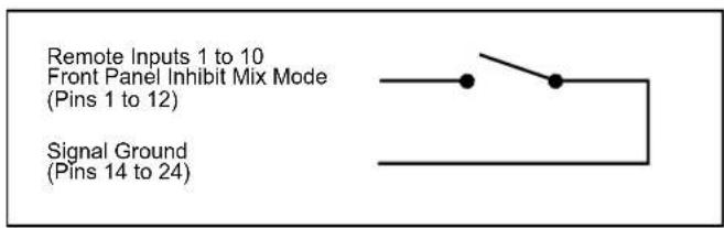
Fig 1-9: Connection Example
Status Outputs
This 25 way D-type socket (female) connector contains the remote status tallies.
| Pin No. Signal | Name I/O Description | |
| Pin 1 REMTALLY1 O | Internal open collector to ground for output 1 | |
| Pin 2 REMTALLY2 O | Internal open collector to ground for output 2 | |
| Pin 3 REMTALLY3 O | Internal open collector to ground for output 3 | |
| Pin 4 REMTALLY4 O | Internal open collector to ground for output 4 | |
| Pin 5 REMTALLY5 O | Internal open collector to ground for output 5 | |
| Pin 6 REMTALLY6 O | Internal open collector to ground for output 6 | |
| Pin 7 REMTALLY7 O | Internal open collector to ground for output 7 | |
| Pin 8 REMTALLY8 O | Internal open collector to ground for output 8 | |
| Pin 9 REMTALLY9 O | Internal open collector to ground for output 9 | |
| Pin 10 REMTALLY10 O | Internal open collector to ground for output 10 | |
| Pin 11 N/C - No internal connection | ||
| Pin 12 N/C - No internal connection | ||
| Pin 13 GND - Signal ground | ||
| Pins 14 to 23 +5V O To supply up to a maximum of 500mA | ||
| Pin 24 N/C - No internal connection | ||
| Pin 25 N/C - No internal connection | ||
Fig 1-10: Status Output Pin Connections
Pins 1 to 10 are to replicate the front panel push button indicators and have a maximum sink current of 100mA per pin. An example of how to connect the signals is shown below.
Pins 11, 12, 24 and 25 have no connection inside the unit.

Fig 1-11: Connection Example
1 Mixers, Source Selectors & Switchers - RB- SS10
Technical Specifications RB-SS10
Audio Specifications
| Input Impedance: 20kΩ bridging |
| Output Impedance: | <50Ω |
| Maximum Input Level: +28dBu |
| Maximum Output Level: +28dBu |
| Frequency Response: 20Hz to 20kHz ±0.1dB (600Ω load, ref 1kHz) |
| Input Gain Range: Adjustable 8dB loss to 20dB gain (L & R adjust). |
| Common Mode Rejection:>66dB typically |
| Noise: -96dB unity gain ref +8dBu |
| Max Headphone Output | +12dBu |
| Level: |
Equipment Type
| RB-SS10: | RK3 | 10 way stereo analogue source selector/mixer |
Physical Specifications
| Dimensions (Raw): | 48cm (W) x 10.8cm (D) x 4.2cm (H) (1U) |
| 19" (W) x 4.3" (D) x 1.7" (H) (1U) | |
| Dimensions (Boxed): 53cm (W) x 20.5cm (D) x 6cm (H) |
| 21" (W) x 8" (D) x 2.4" (H) |
| Weight: | Nett: 1.5kg | Gross: 2.0kg |
| Nett: 3.3lbs | Gross: 4.4lbs |
Connections
| Inputs: 4 x XLR 3 pin female (2 x stereo) (balanced, can be unbalanced) |
| 2 x 25 way D-type socket (female) (4 stereo |
| balanced |
| channels on each) |
| Outputs: 2 x XLR 3 pin male (stereo balanced, can be unbalanced) |
| Remote Start I/O: 25 way D-type plug (male) |
| Remote Select/ Switch 25 way D-type socket (female) |
| Inputs: |
| Status Outputs: 25 way D-type socket (female) |
| Mains Input: | Filtered IEC, 110V-120V, or 220-240V switchable, fused, 6W maximum. |
| Fuse Rating: | Anti-surge fuse 160mA 20 x 5mm (230VAC) |
| Anti-surge fuse 315mA 20 x 5mm (115VAC) |
2 RB-DSS10 10 Way Stereo Digital Source Selector
Introduction


Fig 2-1: RB-DSS10 Front Panel
The RB-DSS10 10 Way stereo Digital Source Selector is a 1U rack-mount which produces an AES/EBU and S/PDIF level digital audio output from 10 selectable AES/EBU or S/PDIF digital input signals. There are 10 illuminated front panel push buttons, which select and indicate the current channel selection. The selection and indication is also available through a remote connector on the rear panel. To stop accidental front panel selection there is a remote input to inhibit the front panel buttons.
The digital receivers in this unit are fully 24 bit, 96kHz capable. When an input is selected from the front panel, or remotely, the unit will attempt to capture the incoming signal on either the AES/EBU or the S/PDIF signal inputs, with priority given to the AES/EBU input. If the AES/EBU signal becomes locked while the S/PDIF signal is routed, the unit will automatically switch to the incoming AES/EBU signal.
Once the receiver has successfully locked to a digital input, the LED illuminates, the tally is made, and the audio is routed simultaneously to both the digital audio outputs and converted to analogue audio for monitoring on the front panel headphone socket. If the incoming audio signal is not present, the push button LED and remote tally flash to indicate that the incoming digital signal is missing.
The headphone output has its own volume control, which is independent of the level adjustment for the main outputs, and has a maximum output level of +12dBu.
As well as routing the selected audio signal, the unit will also route a remote signal input through the remote connector to the selected input source, for starting external audio equipment, such as a CD player.
There is a designation strip on the front panel, useful for giving the buttons a meaningful description.
The LED on the front panel is used to indicate that power is present on the unit. However, it also has a secondary role to indicate whether the selected channel is routing the AES/EBU (red LED) or S/PDIF input (amber LED).
2 Mixers, Source Selectors & Switchers - RB- DSS10
System Block Diagram
![graph TD A["Remote Start I/O"] -->|Remote Start In| B["MCU"] C["Remote Select/Switch Inputs"] --> B D["Push Button Switches"] --> B B --> E["Data Selector"] E --> F["Data Selector"] F --> G["AES Receiver"] G --> H["AES Receiver"] H --> I["S/PDIF Output"] J["Inputs"] --> K["AES/EBU"] K --> L["AES Rec…](/content/2026/06/1225749/images/ac076884045ed2c180a2348c745454b0f8b9e49cf1db2ebf496239081993a50a.jpg)
Fig 2-2: RB-DSS10 System Block Diagram
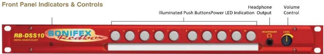
Fig 2-3: RB-DSS10 Front Panel
Power Indicator
The LED on the front panel is used to indicate that power is present on the unit. However, it also has a secondary role to indicate whether the selected channel is routing the AES/EBU or S/PDIF input:
Red indicates AES/EBU input.
Amber indicates S/PDIF input.
The LED and remote tally flash, if the incoming audio signal is not present, to indicate that the incoming digital signal is missing.
Illuminated Push Buttons
The front panel contains 10 illuminated push buttons, used for selecting a digital source. The push button illuminates when the input is selected and flashes when the selected input loses lock.
There is also a remote input to inhibit the front panel switches. When the front panel inhibit is active, pressing the front panel switches has no effect on the current channel selection.
Headphone Output
The output available on the front panel through a 1/4 " stereo jack socket, is designed to drive 150 mW into 32Ω to 600Ω professional headphones.
Volume Control
The headphone output has its own volume control and has a maximum output level of +12dBu.
Additional Modes
An option to set the unit in different modes of operation is available and can be configured at anytime while the unit is powered.
There are currently three modes of operation: Alternate mode, Latched mode and Protected Alternate mode: -
Alternate Mode
In this mode the channels are selected and deselected by a press of the button, as described previously.
Latched Mode
In this mode the selected channel is active only while the button is pressed. As soon as button is released the channel becomes inactive.
Protected Alternate Mode
Operates in a similar manner to the Alternate mode, but a channel cannot be turned off unless switching to another input. In other words, there will always be a channel routed to the output. NOTE: after setting this mode there will be no channel selected.
Select & Confirm Mode
In this mode, input button 10 acts as a CONFIRM button for input selection 1 to 9. Once one of the inputs is pressed, this selection will then flash along with button 10. You must press button 10 within 5 seconds to confirm the selection or the original input selection times out. Only inputs 1 to 9 are selectable and there is always an input channel routed in this mode. NOTE: Initially, after setting this mode there will be no input selected.
Configuring the Additional Modes
While the unit is powered, hold down the input 10 button and press the input 5 button five times. Once completed, the input 10 button will start to flash and the first 3 input buttons will display the current operating mode (as shown below). To change the mode, simply press the input 10 and the buttons will indicate the newly selected mode. Once the required operating mode has been set the unit will restart within five seconds from the last button press.
2 Mixers, Source Selectors & Switchers - RB- DSS10
| INPUT 1 button on = Alternate mode | |
| INPUT 2 button on = Latched mode | |
| INPUT 3 button on = Protected Alternate mode | |
| INPUT 4 button on = Select & Confirm mode | |
Rear Panel Connections and Operation

RB-DSS10 Inputs
AES/EBU Inputs
The 8 digital input XLR 3 pin sockets have an impedance of 110Ω. They have the following connections:
Pin 1: Screen
Pin 2: Phase
Pin 3: Non-phase
The signals on this connector should meet the IEC 60968 specification
RB-DSS10 Outputs
AES/EBU Outputs
The digital output XLR 3 pin socket has an impedance of 110Ω. It has the following connections:
Pin 1: Screen
Pin 2: Phase
Pin 3: Non-phase
The signals on these connectors will comply with the IEC 60968 specification
Digital Audio Inputs & S/PDIF Output
This connector contains the other two remaining professional AES/EBU input connections, and the 10 S/PDIF input connections. It also has the S/PDIF digital output. The S/PDIF digital inputs and the output have an impedance of 75Ω.
| Pin No. I/O Description | |
| Pin 1 I AES/EBU input 9 signal phase | |
| Pin 2 - Signal ground | |
| Pin 3 I AES/EBU input 10 signal non-phase | |
| Pin 4 I S/PDIF Input 1 signal | |
| Pin 5 I S/PDIF input 2 signal | |
| Pin 6 I S/PDIF input 3 signal | |
| Pin 7 I S/PDIF input 4 signal | |
| Pin 8 I S/PDIF input 5 signal | |
| Pin 9 I S/PDIF input 6 signal | |
| Pin 10 I S/PDIF input 7 signal | |
| Pin 11 I S/PDIF input 8 signal | |
| Pin 12 I S/PDIF input 9 signal | |
| Pin 13 I S/PDIF input 10 signal | |
| Pin 14 I AES/EBU input 9 signal non-phase | |
| Pin 15 I AES/EBU input 10 signal phase | |
| Pins 16 to 23 - Signal ground | |
| Pin 24 O S/PDIF output signal | |
| Pin 25 - Signal ground | |
Fig 2-5: Digital Audio Inputs and S/PDIF Output Pin Connections
Note: The actual phase of the AES/EBU signals is not relevant.
Remote Start I/O
This 25 way D-type plug (male) connector contains the remote start input connection and the corresponding 10 opto-isolated remote start outputs.
| Pin No. I/O Description | |
| Pin 1 O Start output 1 collector | |
| Pin 2 O Start output 2 collector | |
| Pin 3 O Start output 3 collector | |
| Pin 4 O Start output 4 collector |
| Pin 5 O Start output 5 collector |
| Pin 6 O Start output 6 collector |
| Pin 7 O Start output 7 collector |
| Pin 8 O Start output 8 collector |
| Pin 9 O Start output 9 collector |
| Pin 10 O Start output 10 collector |
| Pin 11 - No internal connection |
| Pin 12 - No internal connection |
| Pin 13 I Remote start input signal |
| Pin 14 O Start output 1 emitter |
| Pin 15 O Start output 2 emitter |
| Pin 16 O Start output 3 emitter |
| Pin 17 O Start output 4 emitter |
| Pin 18 O Start output 5 emitter |
| Pin 19 O Start output 6 emitter |
| Pin 20 O Start output 7 emitter |
| Pin 21 O Start output 8 emitter |
| Pin 22 O Start output 9 emitter |
| Pin 23 O Start output 10 emitter |
| Pin 24 - No internal connection |
| Pin 25 - Signal ground |
Fig 2-6: Remote Start Pin Connections.
These signals should be connected to external equipment, such as a CD player (as shown following). The collector connects to the start pin of the equipment, and the emitter connects to the common pin of the equipment.
2 Mixers, Source Selectors & Switchers - RB- DSS10
| Start OutputCollector 1 to 10(Pins 1 to 10) | —— | PlayCommand |
| Start OutputEmitter 1 to 10(Pins 14 to 23) | —— | CommandCommon |
Fig 2-7: Connection Example
Remote Select/Switch Inputs
This 25 way D-type socket (female) connector contains the front panel inhibit input connection and the remote switch inputs to control the channel selection.
| Pin No. I/O Description | |
| Pin 1 I Remote input 1 – active low | |
| Pin 2 I Remote input 2 – active low | |
| Pin 3 I Remote input 3 – active low | |
| Pin 4 I Remote input 4 – active low | |
| Pin 5 I Remote input 5 – active low | |
| Pin 6 I Remote input 6 – active low | |
| Pin 7 I Remote input 7 – active low | |
| Pin 8 I Remote input 8 – active low | |
| Pin 9 I Remote input 9 – active low | |
| Pin 10 I Remote input 10 – active low | |
| Pin 11 I Front panel inhibit signal – active low | |
| Pin 12 - No internal connection | |
| Pin 13 - No internal connection | |
| Pins 14 to 24 - Signal ground | |
| Pin 25 - No internal connection | |
Fig 2-8: Remote Select/Switch Input Connections
Status Outputs
This 25 way D-type socket (female) connector contains the remote status tallies.
| Pin No. | Signal Name I/O Description | ||
| Pin 1 | REMTALLY Y1 O | Internal open collector to ground for output 1 | |
| Pin 2 | REMTALLY Y2 O | Internal open collector to ground for output 2 | |
| Pin 3 | REMTALLY Y3 O | Internal open collector to ground for output 3 | |
| Pin 4 | REMTALLY Y4 O | Internal open collector to ground for output 4 | |
| Pin 5 | REMTALLY Y5 O | Internal open collector to ground for output 5 | |
| Pin 6 | REMTALLY Y6 O | Internal open collector to ground for output 6 | |
| Pin 7 | REMTALLY Y7 O | Internal open collector to ground for output 7 | |
| Pin 8 | REMTALLY Y8 O | Internal open collector to ground for output 8 | |
| Pin 9 | REMTALLY Y9 O | Internal open collector to ground for output 9 | |
| Pin 10 | REMTALLY Y10 O | Internal open collector to ground for output 10 | |
| Pin 11 | N/C | - | No internal connection |
| Pin 12 | N/C | - | No internal connection |
| Pin 13 | GND | - | Signal ground |
| Pins 14 to 23 +5V | O | To supply up to a maximum of 100mA | |
| Pin 24 | N/C | - | No internal connection |
| Pin 25 | N/C | - | No internal connection |
Fig 2-9: Status Output Pin Connections
Mixers, Source Selectors & Switchers - RB- DSS10
Pins 1 to 10 are to replicate the front panel push button indicators. An example of how to connect the signals is shown below.
Pins 11, 12, 24 and 25 have no connection inside the unit.
+5V (Pins 14 to 23)
Remote Tally 1 to 10 (Pins 1 to 10)
Fig 2-10: Connection Example
Technical Specifications RB-DSS10
Audio Specifications
Input Impedance: 110Ω ±20% balanced (AES/EBU)
Input Impedance: 75Ω ±5% unbalanced (S/PDIF)
Output Impedance: 110Ω ±20% balanced (AES/EBU)
Output Impedance: 75Ω ±5% unbalanced (S/PDIF)
Signal Level: 3V/10V peak to peak min/max (AES/EBU) 0.5V ±20% peak to peak (S/PDIF)
Sample Freq Range: 30-100kHz (i.e. including 32kHz, 44.1kHz, 48kHz, 64kHz, 88.2kHz and 96kHz), following input signal
Bit Depth: 16 - 24 bits, following input signal
Max Headphone Output Level: +12dBu
Audio Connections
Audio Inputs: 8 x AES/EBU XLR 3 pin female 2 x AES/EBU (part of 1 x 25 way D-type plug) 10 x S/PDIF (part of 1 x 25 way D-type plug)
Audio Outputs: 1 x AES/EBU XLR 3 pin male 1 x S/PDIF (part of 1 x 25 way D-type plug)
Other Connections
Remote Start I/O: 1 x 25 way D-type plug (male)
Remote Input Select
& Switch Inputs: 1 x 25 way D-type socket (female)
Status Outputs: 1 x 25 way D-type socket (female)
Mains Input: Filtered IEC, continuously rated 85-264VAC @ 47-63Hz, max 10W
Fuse Rating: Anti-surge fuse 1A 20 x 5mm
Equipment Type
RB-DSS10 10 way stereo digital source selector

Physical Specifications
Dimensions (Raw): 48cm (W) x 10.8cm (D) x 4.2cm (H) (1U) 19" (W) x 4.3" (D) x 1.7" (H) (1U)
Dimensions (Boxed): 53cm (W) x 20.5cm (D) x 6cm (H) 21" (W) x 8" (D) x 2.4" (H)
Weight: Nett: 1.6kg Gross: 2.2kg
3 Mixers, Source Selectors & Switchers - RB- PMX4
3 RB-PMX4 10 Input, 4 Output Analogue Preset Mixer
Introduction

Fig 3-1: RB-PMX4 Front Panel
The RB-PMX4 is a high performance 10 mono input to 4 mono output preset mixer. Each of the four outputs has a 10 way DIP switch associated with it to select which of the 10 inputs are routed to it. So, by altering the DIP switches, any of the input sources can be mixed to any of the outputs. The DIP switches are enclosed by a screw-on cover on the front panel so that the settings can not be accidentally changed for secure applications.
The RB-PMX4 has been designed for situations where a small mixer is needed for installations where it will be configured and then only altered occasionally, or never altered. Uses for this product are numerous including a four bus mini-mixer, a 4 zone mixer for pubs and clubs, a multiple clean-feed generator and a quad stereo to mono converter to name a few.
The XLR-3 inputs and outputs are electronically balanced and can be wired unbalanced. Each output is individually buffered so that a short circuit on one won't affect the others. Each input has its own gain control which is a pre-set potentiometer accessible through the front panel. This provides gain adjustment of -8dB to 18db. This is useful for normalizing consumer and professional signals to give outputs of -15dBu and 0dBu respectively.
The front panel is held on by 2 off M3 x 6 stainless steel dome-head screws and can be removed using a 2mm AF hex key (allen key). Each 10-way switch represents an output and the individual switches represent the inputs that will be mixed to that output. Switches are in the ON (down) position to be mixed and the OFF (up) position for off.
The XLR-3 outputs are electronically balanced and can be wired unbalanced. Each output is individually buffered so that a short circuit on one won't affect the others.
An LED power indicator on the front panel displays the power supply connection.
System Block Diagram
![graph TD A["Balanced XLR Input 1"] -->|Gain| B["Output 1 Switch Bank"] C["Balanced XLR Input 2"] -->|Gain| B D["Balanced XLR Input 3"] -->|Gain| B E["Balanced XLR Input 4"] -->|Gain| B F["Balanced XLR Input 5"] -->|Gain| B G["Balanced XLR Input 6"] -->|Gain| B H["Balanced XLR Input 7"] -->|Gain| B I…](/content/2026/06/1225749/images/7be04663ea2f08a8536a446e5a17b311576a6018792afcd896111cde9d5c3c01.jpg)
Fig 3-2: RB-PMX4 Block Diagram
3 Mixers, Source Selectors & Switchers - RB- PMX4
Rear Panel Connections and Operation

Fig 3-3: RB-PMX4 Rear Panel
Inputs 1-10
The XLR-3 input sockets can take balanced professional levels, or unbalanced by using the front panel gain controls, and by connecting the non-phase to the signal ground screen. The XLR 3 pin input has the following connections:
Pin 1: Screen
Pin 2: Phase
Pin 3: Non-phase
Outputs 1-4
The XLR 3 pin output plugs are electronically balanced, and can be wired unbalanced. Each output is individually buffered so that a short circuit on one output will not affect the others. They have the following connections:
Pin 1: Screen
Pin 2: Phase
Pin 3: Non-phase
Front Panel Controls
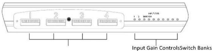
Fig 3-4: RB-PMX4 Front Panel Controls
Switch Banks
There are 4 off 10-way switch banks, one for each output. Using these switches, each input channel can be individually selected to each output. When the switches are up (OFF) position, they are off and mixed when in the down (ON) position.
Input Gain Controls
The gain for each input may be individually varied from -8dB to 18dB by adjusting the pre-set potentiometers, which are accessible through the holes in the front panel.
This is useful for normalising consumer and professional signals to give outputs of -15dBu and 0dBu respectively.
Technical Specifications RB-PMX4
Audio Specifications
Maximum Input Level: +28dBu
Input Impedance: >20kΩ balanced bridging
Maximum Output Level: +28dBu
Output Impedance: <50Ω
Frequency Response: 20Hz to 20kHz ±0.1dBu (600 Ω load, @ 1kHz)
Input Gain Range: Adjustable 8dBu loss to 18dBu gain.
Common Mode Rejection:>60dBu typically
Off-isolation/Crosstalk: >90dBu @ 1kHz
Noise: -86dBu RMS 22Hz-22kHz, unity gain, ref +8dB
Distortion: <0.01% @ 1kHz, 0dBu to +26dBu
Connections
Inputs: 10 x XLR 3 pin female (Balanced, can be unbalanced)
Outputs: 4 x XLR 3 pin male (Balanced, can be unbalanced)
Mains Input: Filtered IEC, 110V-120V, or 220-240V switchable, fused, 6W maximum
Fuse Rating: Anti-surge fuse 100mA 20 x 5mm (230VAC) Anti-surge fuse 250mA 20 x 5mm (115VAC)
Equipment Type
RB-PMX4:
10 input, 4 output analogue preset mixer

Physical Specifications
Dimensions (Raw): 48cm (W) x 10.8cm (D) x 4.2cm (H) (1U) 19" (W) x 4.3" (D) x 1.7" (H) (1U)
Dimensions (Boxed): 53cm (W) x 20.5cm (D) x 6cm (H) 21" (W) x 8" (D) x 2.4" (H)
Weight: Nett: 1.5kg Gross: 2.2kg
4 Mixers, Source Selectors & Switchers - RB-DMX4
4 RB-DMX4 4 x 4 Channel Digital Audio Mixer/Router
Introduction


Fig 4-1: RB-DMX4 Front Panel
The RB-DMX4 is a digital mixer capable of mixing or routing 4 mono input channels into 4 mono outputs, or 2 stereo inputs into 2 stereo outputs. The inputs are sample rate converted to allow sources of different sample rates to be mixed. The flexible Mix Matrix allows for a wide variety of mixing options and creativity, using 4 blocks of 4 way DIPswitches to select which inputs are mixed or routed to which outputs.
The RB-DMX4 has 4 x digital mono audio inputs, each one selectable in pairs via front panel INPUTS 1 & 2 and INPUTS 3 & 4 push buttons, from either AES/EBU balanced XLRs, S/PDIF unbalanced phonos or TOSlink unbalanced optical inputs. Sample rate converters on each input mean that sources of different sample rates can be used with the output sample rate being defined independently. The colour of the INPUTS 1 & 2 and INPUTS 3 & 4 push-buttons indicate whether the input source is synchronised (no colour) or not (flashing green and red).
Each input has a trim pot, which can be used to attenuate the input signal. This allows for a perfect mix of channels at different audio levels. Audio presence LEDs around each input button give an indication of input audio level. There is one LED for each channel. There are also 4 presence LEDs around the MONITOR button which give an indication of output level. Additional gain can be added by accessing the OUTPUT GAIN mode.
There are 2 stereo outputs which are available as simultaneous AES/EBU
balanced XLRs, S/PDIF unbalanced phonos or TOSlink unbalanced optical outputs. The output sample rates are selectable via rear panel DIPswitches from one of 32kHz, 44.1kHz, 48kHz, 88.2kHz, 96kHz, 176.4kHz or 192kHz.
The unit has TTL wordclock BNC and AES/EBU XLR synchronising inputs as standard and optionally, the RB-SYA and RB-SYD synchronisation boards can be fitted to synchronise the unit to analogue or digital video signals. A rear panel DIPswitch block is used to decide whether the unit is synchronised to Input 1 & 2, Input 3 & 4, the AES/EBU sync input, the wordclock sync input or an optional video sync board. The DIPswitch block also selects the synchronisation mode of the unit and the MONITOR button flashes whenever the unit is not synchronised to an incoming sync signal. Selectable sync modes are as follows:
Master Mode
In this mode the digital output sample rate is simply set by, and locked to, the internal on-board clock generator. No sync signal is used or required.
Auto Sync Mode
In this mode the digital output sample rate follows the selected sync input. When the sync signal is not present the output sample rate will be set by, and locked to, the internal on-board clock generator at the selected output frequency.
Auto Lock Mode
The digital output sample rate follows the sync input. If the sync signal is removed then the output sample rate will be set by, and locked to, the internal on-board clock generator at the closest frequency available to the previous sync input.
Slave Mode
In this mode the digital output sample rate follows the sync input. When the sync signal is not present the digital output is turned off.
There is a monitor socket on the front panel with a gain pot to allow you to monitor the output of each channel. The monitored channel can be
selected via a push button on the front panel which, when held, can also supply up to 12dB of gain. If the level that is being monitored is close to full scale, a 12dB attenuation can be added to the monitor channel via a DIPswitch on the rear panel.
The unit can be placed in mono or stereo mode via rear panel DIPswitch. Stereo mode allows you to monitor the two input pairs as stereo channels as well as controlling the input gain as a pair, giving tied audio levels.
The RB-DMX4 has been designed to have a passive signal path through the main input, so if power to the unit fails, signal inputs 1 & 2 are routed to outputs 1 & 2 and signal inputs 3 & 4 are routed to outputs 3 & 4. This is
![graph TD A["Digital Input 1"] --> B["Digital Source Select"] B --> C["RX SRC"] C --> D["DSP"] D --> E["TX"] E --> F["Power Failure Relay"] F --> G["Power Failure Relay"] H["Optical"] --> I["AES"] I --> J["Freq Select"] J --> K["Master Clock Generation"] K --> L["AES RX"] L --> M["Clock Select"] M --…](/content/2026/06/1225749/images/c77c06da0ccadeb0803984fac706e9f83cb3d19fde0088e42ebf271a9f349e30.jpg)
Fig 4-2: RB-DMX4 System Block Diagram
4 Mixers, Source Selectors & Switchers - RB-DMX4
essential for applications such as installation at transmitter sites, where a power failure to the unit should not prevent the audio input signal from being output to the transmitter. Please note that this is not true for the TOSLink outputs which are muted.
The RB-DMX4 can be controlled using Sonifex free software, SCi. Contact Sonifex for further information if you have a particular requirement that isn't catered for by the RB-DMX4 as standard.
Front Panel Controls and Indicators
The LED on the front panel is normally red to indicate power to the unit.

Fig 4-3: RB-DMX4 Front Panel Controls and Indicators
Output Mix Matrix Selection Using The Front Panel DIPSwitches
The OUTPUT MIX front panel DIPSwitches are concealed behind the screw panel located on the front of the unit and they decide which input channels are mixed to which output channels. There are 4 banks of DIPSwitches, each representing an output channel.
To mix an input to that channel, simply lift the DIPSwitch for the desired input channel. In total, 4 mono channels can be mixed together on each mono output channel.
This allows many mixing configurations and maximum flexibility. Adding to that, mixing can be achieved between all the different input types at all sample rates. See page 24 for applications for the product using different matrix settings.

Fig 4-4: RB-DMX4 Front Panel DIPSwitches
INPUT 1 & 2 Source Select Button, Indicators & Input Presence LEDS
This button allows you to select which of the digital input sources you would like to use. The three LEDs above the button illustrate which source is selected. The button also indicates whether the input is locked - it flashes green and red if the input is unlocked and is unlit when locked.
The bicolour LEDs, marked '1' and '2', show input presence and give an indication of the input level using the AES digital standard with the following colours:
- INF lt; - 5 2 dBFS = OFF
- 5 2 dBFS lt; - 3 dBFS = GREEN
- 3 dBFS lt; 0 dBFS = ORANGE
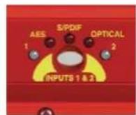
Fig 4-5: RB-DMX4 INPUT 1 & 2 Select Button
INPUT 3 & 4 Source Select Button, Indicators & Input Presence LEDs
The operation of this button is identical to the INPUT 1 & 2 button but acts on inputs 3 & 4.
INPUT GAIN Pots
These pots allow the gain of each individual channel to be trimmed so that the perfect mix can be achieved. Simply turn anti-clockwise to attenuate the level or clockwise to restore it. Fully clockwise is unity gain. Fully anti-clockwise is muted.
In Stereo Mode, pots 1 and 3 control the gain for channels 1 & 2 and 3 & 4 respectively. See page 25 for further information.

Fig 4-6: RB-DMX4
INPUT Gain Pots
MONITOR Button & Output Presence LEDs
Normally, this button displays the external synchronisation status and the four LEDS around it display output presence. If the selected synchronisation source is unlocked, the button will flash green and red. A button press allows you to choose which channel is output through the headphone socket and to set-up the output gain.
For monitor selection, the button illuminates red, as does the LED of the selected channel. For output gain, the LEDs around the button illuminate in green sequentially indicating the level of gain applied.
MONITOR Button Modes
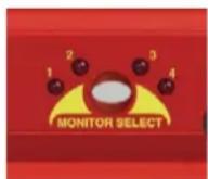
Fig 4-7: RB-DMX4
MONITOR Button
The MONITOR button has three modes of operation with different functions: Display Mode, Monitor Output Select Mode and Output Gain Mode:
Display Mode
Display Mode is the default mode of the button. In display mode, the four surrounding bicolour LEDs act as presence LEDs for the output channels. Marked '1' to '4', the LEDs give an indication of the output level using the AES digital standard with the following colours:
- INF lt; - 5 2 dBFS = OFF
- 5 2 dBFS lt; - 3 dBFS = GREEN
- 3 dBFS lt; 0 dBFS = ORANGE
0 dBFS / CLIP = RED(AGCOperational)
Note re Clipping: The AGC is working on a channel if its output presence LED is red. The mixing in this unit is achieved by the summation of 24 bit audio values. The total of this summation could, if uncorrected, breach the upper limit of a 24 bit number, which would lead to clipping. The unit detects these occurrences and adds an instantaneous attenuation to bring the signal in range again. This attenuation factor will decrease on a slow decay until 0dBFS is achieved, or until another breach occurs. The slow decay eliminates any breathing or pumping effects in the audio.
If the unit is set to be synchronized externally but is not synchronized, the button flashes green and red continuously. If it is synchronised, or the unit is set to MASTER sync mode, the button is unlit.
4 Mixers, Source Selectors & Switchers - RB-DMX4
Monitor Output Select Mode
To enter Monitor Output Select Mode, simply press and release the MONITOR button. The button turns red and the surrounding LEDs now display which output is selected for monitoring, in red. This mode will last for two seconds, which is refreshed every time the button is pressed and released. If the unit is in Stereo Mode, LEDs 1 & 2 illuminate together, as do 3 & 4. See page 25 for configure the unit in Stereo Mode.
Output Gain Mode
To enter Output Gain Mode, first enter Monitor Output Select Mode and select the channel which you would like to apply gain to. Within two seconds, press and hold the MONITOR button until the button changes from red to green. On release of the button, the surrounding LEDS will now switch to display the current output gain for this channel. Press and release the button to choose the output gain levels from one of:
LED 1 Green: 0dB
LED 2 Green: +3dB
LED 3 Orange: +6dB
LED 4 Red: +12dB
After choosing your required setting, press and hold the button until it changes colour from solid green. This will return the button to the Display Mode.
Note: Make sure that you check the presence LEDs to ensure that the output is not clipping.
SERIAL LED Indicator
If the rear panel Serial Mode DIPSwitch 11 is ON, then this LED illuminates. In this mode, the unit is being controlled serially using the Sonifex SCI software.
Fig 4-8: RB-DMX4 Serial Control Indicator LED
Headphone Output
The front panel headphone output is a 1/4 " (6.35mm) stereo jack socket capable of delivering over 80mW into 32Ω - 600Ω professional headphones at full volume. Higher impedance headphones may be used at reduced levels. Lower impedance headphones should not be used.
Please be aware that this headphone amplifier has been designed to cope with the varying different headphone and full scale line-up set-ups that are used. Consequently, the monitor attenuation DIPSwitch 10 should be turned on if the output sounds very loud and distorted at any time.
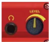
Fig 4-9: RB-DMX4
Headphone Output &
Level Control
LEVEL Control
The front panel LEVEL control is a potentiometer that adjusts the level of the monitor output and provides a gain range of -70dB to +12dB.
Reset Button
In the unlikely event that the RB-DMX4 unit fails to respond, press the reset button to reboot the unit (see Fig 2-1 for location).
Rear Panel DIPSwitch Controls
The SETTINGS DIPSwitch block on the rear panel is used to configure the RM-DMX4:
Master Mode Sample Rate Selection (DIPSwitches 1-3)
These DIPSwitches allow you select which sample rate the output is set to when the unit is synchronised to the Master Mode. Set the DIPSwitches where:
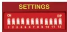
Fig 4-10: RB-DMX4 Rear Panel DIPSwitch Block
| Sample Rate (kHz) | DIPSwitch 1 | DIPSwitch 2 | DIPSwitch 3 |
| 32 OFF OFF | OFF | ||
| 44.1 ON OFF | OFF | ||
| 48 OFF ON | OFF | ||
| 88.2 ON ON | OFF | ||
| 96 OFF OFF | ON | ||
| 176.4 ON OFF | ON | ||
| 192 OFF ON | ON |
Synchronisation Source Selection (DIPSwitches 4-6)
These DIPSwitches allow you select which input sync source is used to synchronise the unit to. Set the DIPSwitches where:
| Synchronisation Source | DIPSwitch 4 DIPSwitch 5 DIPSwitch 6 | |
| Input 1 & 2 OFF OFF OFF | ||
| Input 3 & 4 ON OFF OFF | ||
| AES/EBU Sync Input | OFF ON OFF | |
| Word Clock Input ON ON OFF | ||
| Video Sub Board OFF OFF ON | ||
Synchronisation Mode Selection (DIPSwitches 7-8)
These DIPSwitches allow you select the active sync mode. Set the DIPSwitches where:
| Synchronisation Mode DIPSwitch 7 DIPSwitch 8 | ||
| Master Mode OFF OFF | ||
| Auto Sync Mode ON OFF | ||
| Auto Lock Mode OFF ON | ||
| Slave Mode | ON ON | |
Stereo/Mono Operation of Input Gain and Monitor Select (DIPSwitch 9
This defines whether the unit operates the input gain and monitor functions as a stereo pair or as mono channels.
| Mode | DIPSwitch 9 | Description |
| Stereo | ON | When ON, the gain applied to input 1 using pot 1 also alters the gain for input 2.Also when ON, the headphone monitor outputs a stereo signal made up of either Input 1 & 2 or Input 3 & 4. |
| Mono | OFF | When OFF, the gain of each channel is controlled individually by a gain pot.In Mono Mode the selected signal is sent to left and right earpieces of the headphone output. |
Monitor Attenuation (DIPSwitch 10)
This defines whether the monitor signal is attenuated by 12dB. This is useful if you're using low impedance headphones which are too loud in everyday use.
| Mode | DIPSwitch 10 | Description |
| Attenuated ON | When ON, the monitor signal is attenuated. | |
| Unattenuated | OFF | When OFF, the monitor signal is unaffected. |
Serial Mode (DIPSwitch 11)
This defines whether the unit is in serial mode. In serial mode the unit is controlled by the serial port, not by its DIPSwitch settings. For example for use with the Sonifex SCI software.
4 Mixers, Source Selectors & Switchers - RB-DMX4
| Mode DIPSwitch 11 | Description | |
| Serial Control ON | When ON, the unit is in serial mode. | |
| DIPSwitch Control OFF | When OFF, the unit is in normal operation. |
Boot Mode (DIPSwitch 12)
With this DIPSwitch ON, the unit powers up into 'Boot Mode'. In this mode, the firmware in the unit can be upgraded using the SCi software. Note that this would be useful if a firmware update to the unit was interrupted, or corrupted which left the unit in an inoperable condition.
| Mode DIPSwitch 12 | Description | |
| Boot Mode ON | When ON, the unit is in Boot Mode. | |
| Normal Operation OFF | When OFF, the unit is operates normally. |
Applications of Use
Each physical input connector (INPUT 1 & 2 or INPUT 3 & 4) supplies the unit with two channels of audio data, left (1 and 3) and right (2 and 4). Similarly, each physical output connector (OUTPUT 1 or OUTPUT 2) supplies the outside world with two channels of audio data, left (1 & 3) and right (2 & 4). These inputs and outputs can be configured in a number of ways for different applications. Here are a few suggested methods of use:
Stereo Mix of Two Stereo Digital Inputs
- Connect two stereo input sources and select on the front panel.
- Raise DIP switch 1 and 3 ON for OUTPUT MIX bank 1.
- Raise DIP switch 2 and 4 ON for OUTPUT MIX bank 2.
- Connect OUTPUT 1 to output equipment.
Mono Mix of Four Input Sources to Create your Own Stereo Output
- Connect four mono inputs (for example four different musical instrument feeds) to the unit and select on the front panel.
- Select which inputs you would like on the LEFT of your stereo output and select ON for OUTPUT MIX bank 1.
- Select which inputs you would like on the RIGHT of your stereo output and select ON for OUTPUT MIX bank 2.
- Connect OUTPUT 1 to output equipment.
One to Four Mono Distribution/ Creating Dual Mono Outputs
- Connect one mono input to the unit INPUT 1 and select on the front panel.
- Raise DIP switch 1 ON for all OUTPUT MIX banks.
- Connect OUTPUTs 1 and 2 to output equipment.
Two to Four Mono Distribution Or Creating Dual Mono Outputs
- Connect two mono inputs to the unit INPUT 1 and select on the front panel.
- Raise DIP switch 1 ON for OUTPUT MIX banks 1 and 2.
- Raise DIP switch 2 ON for OUTPUT MIX banks 3 and 4.
- Connect OUTPUTs 1 and 2 to output equipment.
Four Channel Sample Rate Converter
The RB-DMX4 can be used as a sample rate converter or an input/output converter. To use the unit as a "Straight Through" device and take advantage of those features alone:
- Connect all desired inputs to the unit and select on the front panel.
- Raise DIP switch 1 on OUTPUT MIX bank 1.
- Raise DIP switch 2 on OUTPUT MIX bank 2.
- Raise DIP switch 3 on OUTPUT MIX bank 3.
- Raise DIP switch 4 on OUTPUT MIX bank 4.
- Connect the desired connector of OUTPUT1 and OUTPUT 2 to the output equipment and set the sample frequency that you want to convert to using the SETTINGS DIPSwitches on the rear panel.
Rear Panel Connectors
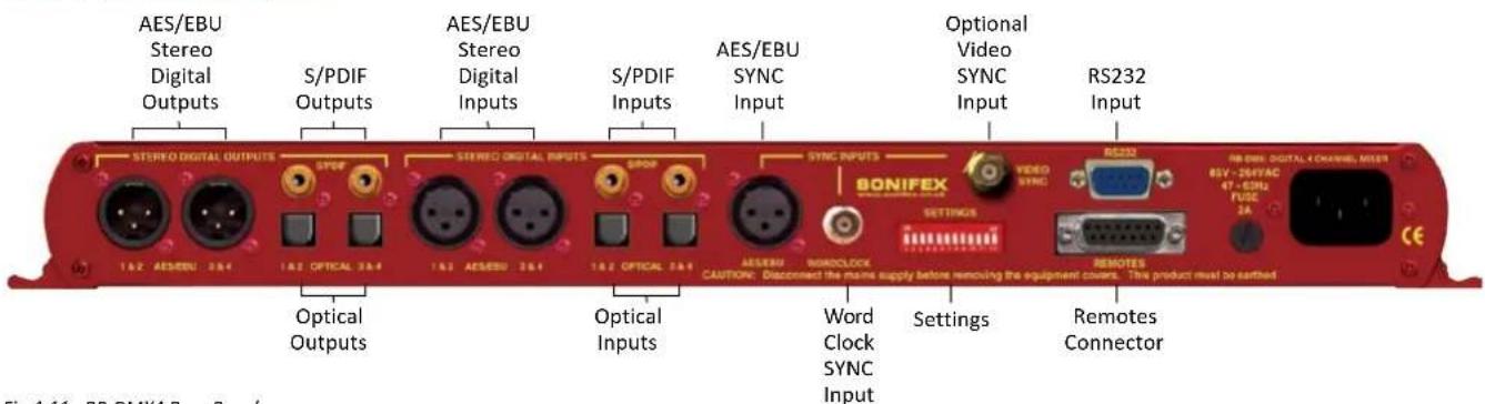
Fig 4-11: RB-DMX4 Rear Panel
AES/EBU Outputs
The 2 stereo digital output XLR 3 pin sockets have an impedance of 110Ω.
They have the following connections:
Pin 1: Screen.
Pin 2: Phase.
Pin 3: Non-phase.
The signals on this connector comply with the IEC 60968 specification
S/PDIF Outputs
The 2 x stereo digital output S/PDIF phono outputs have an impedance of 75Ω.
Optical Outputs
The 2 x stereo digital audio optical outputs meet the TOSLink specification used by most professional & consumer equipment.
The outputs have an unweighted dynamic range of at least 138dB and a THD+N noise of, or better than, -137dB. The data at the outputs is presented as 24 bit wide.
AES/EBU Inputs
The 2 x stereo digital input XLR 3 pin sockets have an impedance of 110Ω.
They have the following connections:
Pin 1: Screen
Pin 2: Phase
Pin 3: Non-phase
The signals on this connector meet the IEC 60968 specification.
S/PDIF Inputs
The 2 x S/PDIF stereo digital phono inputs have an impedance of 75Ω.
4 Mixers, Source Selectors & Switchers - RB-DMX4
Optical Inputs
The 2 x stereo digital audio optical inputs meet the TOSLink specification used by most professional & consumer equipment.
AES/EBU Sync Input
The digital input XLR 3 pin socket has an impedance of 110Ω. It has the following connections:
Pin 1: Screen
Pin 2: Phase
Pin 3: Non-phase
The signals on this connector meet the IEC 60968 specification
Word Clock Input
The TTL Word Clock synchronisation input has an impedance of 50Ω and uses a BNC connector.
Video Sync Input
The video sync input is presented as a 75Ω BNC connector. See page viii for more information on the video sync boards available.
Serial RS232 Connector
The 9-way 'D' type socket connector carries a standard RS232 interface and allows direct connection to a serial port on a PC via a pin-to-pin cable. The pin assignments are as follows:
Pin 2: Transmit data
Pin 3: Receive data
Pin 5: Ground
All other pins are unused.
Remotes Connector
The remotes connector is a 15-way 'D' type socket that is currently reserved for future development. Displayed below are the pin connections and a description of what is available:
Pin 1 – Relay 1 Normally Open
Pin 2 – Relay 1 Normally Closed
Pin 3 – Relay 2 Normally Open
Pin 4 – Relay 2 Normally Closed
Pin 5 – Make to Digital Ground Input
Pin 6 – Internal Open Collector to Digital Ground Output
Pin 7 – Make to Digital Ground Input
Pin 8 – Digital Ground
Pin 9 – Relay 1 Common
Pin 10 – Make to Digital Ground Input
Pin 11 – Relay 2 Common
Pin 12 - 5V Supply Maximum 200 mA
Pin 13 – Internal Open Collector to Digital Ground Output
Pin 14 – Make to Digital Ground Input
Pin 15 – Internal Open Collector to Digital Ground Output
Serial Port Control
The Serial Port allows the RB-DMX4 to be controlled and updated from a PC via a pin-to-pin serial cable, using the Sonifex Serial Control Interface (SCI) software. This software is available as a free download from the Sonifex website at www.sonifex.co.uk/sci.
Default Settings for the Serial Port
Baud Rate: 19200
Data Bits: 8
Stop Bits: 1
Parity: Even
Handshaking: XON/XOFF
Fig 4-12: Serial Port Default Settings
Serial Interface Commands and Responses
Most of the commands follow the same structure: a 3 letter command followed by a colon, followed by a parameter (if any) and terminated by Carriage Return with optional Line Feed. A Line Feed character may be sent but it will be ignored by the RB-DMX4. Commands are not case sensitive.
Responses are CR & LF terminated.
After the RB-DMX4 has been powered-up, an initialisation string is sent "Initialising DMX4".
Following are the commands and the expected responses:
Command Description Response
| Bnn: Baudrate Change -ACK: |
| nn is the new baudrate value where: |
| nn = 11 = 115200kbps |
| nn = 57 = 57600kbps |
| nn = 38 = 38400kbps |
| nn = 19 = 19200kbps |
| nn = 96 = 9600kbps |
DWN: Initiates a Firmware Upgrade -ACK:
| FPS: Front Panel & -FPS:aa_bb_cc_dd_ee_ff_gg_hh_ji_lk |
| Unit Status |
| aa = Input 1 & 2 Source Selection |
| bb = Input 3 & 4 Source Selection |
| where 00 = AES/EBU, 01 = S/PDIF, 02 = TOSLINK |
| cc = Sync Mode Selection |
| where 00 = Master, 01 = Auto, 02 = Auto lock, |
| 03 = Slave mode |
| dd = Serial Flag Indication |
| where 00 = Serial mode off, |
| 01 = Serial mode on |
| ee = Frequency |
| where 00 = 32k, 01 = 44.1k, 02 = 48k, 03 = 88.2k, |
| 04 = 96k, 05 = 176.4k, 06 = 192k |
ff = Monitor Channel
where 00 = OUTPUT1,01 = OUTPUT2, 02 = OUTPUT3,
03 = OUTPUT4
gg = Sync From
where 00 = Input 1, 01 = Input 2, 02 = AES sync,
03 = Word clock, 04 = Video sync
hh = Rear DIPSwitch Settings
where hh is a hex value built from the sum of all applicable from:
01 = Stereo Monitor
02 = Monitor Attenuation
ji = Mix Matrix1 - Output 1(i) and 2(j)
lk = Mix Matrix2 - Output 3(k) and 4(l)
i, j, k and l are hex values built from the sum of:
INPUT 1 = 0x1
INPUT 2 = 0x2
INPUT 3 = 0x4
INPUT 4 = 0x8
FRQ:nn Output Sample Rate Selection -ACK: nn selects which sample rate is selected for the output where:
00 = 32kHz
01 = 44.1kHz
02 = 48kHz
03 = 88.2kHz
04 = 96kHz
05 = 176.4kHz
06 = 192kHz
IGx:nn Input Gain -ACK: x is the channel which will be affected. nn is a hex gain value between 0x00 and 0xFE where: 00 = mute -> FE = 0dBFS
MAT:nn Attenuate Monitor by 12dB -ACK:
nn selects between the two modes
00 = No attenuation
01 = 12 dB of attenuation
4 Mixers, Source Selectors & Switchers - RB-DMX4
MMS:nm Mix Matrix -ACK:
n selects the output channel,
m is a hex value built for the sum of:
INPUT 1 = 0x1
INPUT 2 = 0x2
INPUT 3 = 0x4
INPUT 4 = 0x8
MOD:nn Sync Mode Selection -ACK:
nn selects the synchronization mode where:
00 = Master Mode
01 = Auto Mode
02 = Auto Lock Mode
03 = Slave
MON:nn Select Monitor Channel -ACK:
nn selects which channel is monitored where:
00 = Output 1
01 = Output 2
02 = Output 3
03 = Output 4
MOS:nn Mono or Stereo Selection -ACK:
nn selects between the two options where:
00 = Mono Mode
01 = Stereo Mode
OGx:nn Output Gain -ACK:
x is the channel which will be affected.
nn is a hex gain value between 0x00 and 0x03 where:
00 = 0dBFs
01 = 3dBFs
02 = 6dBFs
03 = 12dBFs
SRQ: Status Request -SRQ:aa_bb_cc_dd_ee_ff_gg_hi_jj_kkkk
aa = Input1 Lock Status
bb = Input2 Lock Status
where 01 = locked and 00 = unlocked
cc = Sync Flash
where 01 = Flashing and 00 = Not flashing
dd = Input Gain For INPUT 1
where dd is a hex value representing the current gain
on this INPUT between:
00 = Mute -> FE = 0dBFs
ee = Input Gain For INPUT 2
where ee is a hex value representing the current gain
on this INPUT between:
00 = Mute -> FE = 0dBFs
ff = Input Gain For INPUT 3
where ff is a hex value representing the current gain
on this INPUT between:
00 = Mute -> FE = 0dBFs
gg = Input Gain For INPUT 4
where gg is a hex value representing the current gain
on this INPUT between:
00 = Mute -> FE = 0dBFs
hi = Output Gain For All OUTPUTS
i is a hex value representing the current gain on outputs 1
and 2 summed and h is a hex value representing the
current
gain on outputs 3 and 4 summed where:
INPUT 1/3
0x00 = 0dB
0x01 = +3dB
0x02 = +6 dB
0x03 = +12 dB
INPUT 2/4
0x00 = 0dB
0x04 = +3dB
0x08 = +6dB
0x0C = +12dB
For example, if INPUT 1 and 2 are set to 3 dB gain and input 3 and 4 are set to 12 dB gain then:
h = 0x03 + 0x0C = 0x0F
i = 0x01 + 0x04 = 0x05
SSx:nn Source Select -ACK:
x selects which input is being changed where:
1 = Input 1
2 = Input 2
nn selects which source is used for that particular
input where:
00 = AES/EBU
01 = S/PDIF
02 = Optical
SYS:nn Sync Source Select -ACK:
nn selects which sync source is used where:
00 = Input 1
01 = Input 2
02 = AES/EBU
03 = Word Clock
04 = Video Sync Board
UID: Unit Id -UID:RB-DSD1
VER: Version Number
VER:x.xxx,y.yyy
Where x.xxx is the firmware version and y.yyy is the front
panel firmware version number
Error Messages
The following error messages can be returned for illegal commands
Err:01-Return if command not found
Err:02-Return if missing parameter
Err:04-Return if parameter out of range
SCi for RB-DMX4
SCi, the Serial Control Interface is free of charge software available on the Sonifex website and allows you to control the RB-DMX4 remotely. The interface has three tabs including a control page, an indication page and a miscellaneous options page. The status of the connection, serial number and firmware versions are always visible at the bottom of the interface.
Note: Make sure that the RB-DMX4 is configured to operate via serial control by setting DIPSwitch 11 to ON. See page 26 for further information.
Status Page

Fig 4-13: Status Page
4 Mixers, Source Selectors & Switchers - RB-DMX4
This page displays the current status of the unit. Each set of inputs has an indicator panel which displays:
Presence Level: The current audio status is displayed as it is on the front panel. (Please refer to page 3).
Locked LED: If the input is locked, this LED is lit.
Input Gain Boxes: Displays the gain of each input channel.
Output Gain Boxes: Displays the gain of each output channel.
Source Label: The source which is currently being used is displayed here.
Synchronization options are displayed in the sync indicator panel:
Mode: This displays the selected synchronisation mode.
Source: This displays the selected synchronisation source. This is disabled in Master Mode.
Sample Rate: This displays the current output sample rate.
Sync Source Locked LED: If the synchronization source is locked this led is lit.
The serial mode LED indicates whether the unit is in serial mode.
Control Page
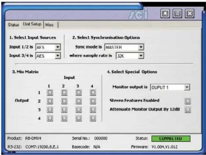
Fig 4-14: Control Page
The Control Page is where you can configure your unit. For ease of use, the options have been split into four sections which you can visit in numbered steps:
1. Select Input Sources
Select which source you would like to use for both the Input 1 & 2 and Input 3 & 4 from the drop down boxes labelled "INPUT 1/2 is" and "INPUT 3/4 is" respectively.
2. Select Synchronisation Options
Select which sync mode to use from the first drop down box, labelled "Sync mode is". If "MASTER" is chosen, then simply select your output sample rate from the drop down box labelled "where sample rate is". If "AUTO",
"AUTOLOCK" or "SLAVE" are selected, then a new drop down box labelled "from" will appear which allows you to select the synchronisation source.
3. Select Mix Matrix
Select which inputs are mixed onto which outputs simply by ticking the boxes in the matrix.
4. Select Special Options
Select which output is monitored by using the drop down box labelled "Monitor output is".
Stereo Features Enabled: Select this tick box for the input gain and headphone monitoring to operate in stereo mode instead of mono.
Attenuate Monitor Output by 12dB: If your headphone monitoring is too loud, select this tick box to attenuate it.
If serial mode is selected, all the controls are enabled. The controls are disabled if serial mode is switched off.
Miscellaneous Page
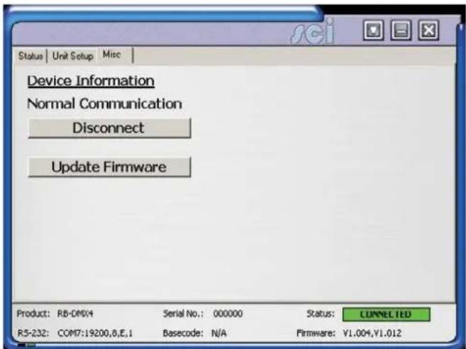
Fig 4-15: Miscellaneous Page
This page is used for the connecting and disconnecting SCi to the unit and for updating the firmware in the RB-DMX4.
Updating The Firmware
The RB-DMX4 firmware will occasionally be updated to add new features or correct any possible issues that may arise. Check for updates at:
https://www.sonifex.co.uk/technical/software/
To update the firmware click on the button labelled "Update Firmware" and then select the downloaded firmware file. Firmware files for the RB-DMX4 always have an ".ldr" extension. A progress bar will appear in SCi, indicating how much of the file has been uploaded to the unit.
4 Mixers, Source Selectors & Switchers - RB-DMX4
When the unit switches to update mode, the front panel display LEDs extinguish. The left program LED is then used to display the status of the upload:
Uploading The Code: The LED flashes amber to confirm the unit is receiving the new firmware to the RAM in the unit.
Copying Code to Flash Memory: The LED is solid amber while the unit checks the integrity of the file and copies the file from RAM to flash memory.
Successful Update: The LED turns green for two seconds and the unit automatically resets and begins running the new code.
Unsuccessful Update: The LED turns red for two seconds and the returns to running the last firmware used.
Technical Specification For RB-DMX4
Audio Specification
Dynamic Range: >138dB
Distortion and Noise: <-137dB THD + N at 1kHz, ref 0dBFS
Input & Output Impedances:110Ω ±20% AES/EBU balanced I/O
75Ω ±5% S/PDIF unbalanced I/O
75Ω ±5% TOSlink unbalanced I/O
50Ω BNC TTL word clock input
Signal Level: Balanced: 3V/10V peak to peak min/max
Unbalanced: Min 0.5V±20% peak to peak
Sample Frequencies: 32, 44.1, 48, 88.2, 96, 176.4 or 192kHz
Bit Depth: Up to and including 24 bit
Front Panel Operational Controls & Indicators
Digital Input Select: AES/EBU, S/PDIF or TOSlink optical
via INPUT 1 & 2 or INPUT 3 & 4 push-buttons
Mix Control: Output mix selection system via front panel
DIPSwitches
Input Gain: Input gain control for four INPUT channels
via potentiometers
Monitor Select Control: Headphone monitor channel select and output
gain via push button
Monitor Volume Control Range: -70dB to +12dB gain
Indicators: Input and output presence indicators via
bicolour LEDS around each push button
Rear Panel Operational Controls
Master Select: 32, 44.1, 48, 88.2, 96, 176.4 or 192kHz
Frequency via rear panel DIPSwitches
Sync Source Select: INPUT 1 & 2, INPUT 3 & 4, AES Sync, Word
Clock, Video Sync via rear panel DIPSwitches
Sync Mode Select: Master, Auto Sync, Auto Lock, Slave via rear
panel DIPSwitches
Stereo Features: Stereo gain control and monitor outputs via rear panel DIPSwitches
Monitor Attenuation: 12dB Monitor attenuation via rear panel DIPSwitches
Serial Mode: Enter serial control mode via rear panel DIPSwitches
Boot Mode: Boot up base code or firmware via rear panel DIPSwitches
Connections
Digital Inputs: 2 x AES/EBU XLR 3 pin female
2 x S/PDIF RCA phono
2 x TOSLink optical input
Digital Outputs: 2 x AES/EBU XLR 3 pin plug
2 x S/PDIF RCA phono socket
2 x TOSLink optical output
Sync Inputs: 1 x AES/EBU XLR 3 pin female
1 x Word Clock BNC
1 x Video Input (optional)
Remote I/O Port: 15 way D-type plug
Serial Port: RS232, 9 way D-type socket
Mains Input: Universal filtered IEC, continuously rated
85-264VAC@47-63Hz, max 10W
Fuse Rating: Anti-surge fuse 2A 20 x 5mm
Equipment Type
RB-DMX4: 4 x 4 channel digital audio mixer/router
RK3
Physical Specifications
Dimensions 48cm (W) x 10.8cm (D*) x 4.2cm (H) (1U)
(Raw): 19" (W) × 4.3" (D*) × 1.7" (H) (1U)
Dimensions 59cm (W) x 27.5cm (D) x 11cm (H)
(Boxed): 23.2" (W) x 10.8" (D) x 4.3" (H)
5 RB-SSML1 Mic/Line Source Selector with Compressor Limiter
Introduction

Fig 5-1: RB-SSML1 Front Panel
The RB-SSML1 is a 1U rack-mountable source selector for compressing or limiting an incoming microphone or stereo line signal and mixing this signal with a stereo monitor input, which can then be metered and mixed to two headphone outputs. The unit is mainly used in situations where level control is required, for example in voiceover applications.
The mic input consists of an independent low-noise microphone pre-amplifier for converting microphone level signals to a line level. There are independent switches to control a high pass filter (low frequency roll-off at 125Hz) and to provide phantom power at +48V to the connected microphone. A preset pot on the rear panel allows adjustment of the mic gain from 36dB to 75dB.
A front panel switch selects between mic and line inputs. Both mic and line inputs have fully adjustable volume control via front panel pots, with the line input having an additional 10dB gain increase via a switch on the rear panel for use with unbalanced equipment. The mono mic input is converted to a stereo signal before being passed to the compressor/limiter.
The XLR-3 stereo monitor input has an adjustable volume control via a back panel recessed pot, and has an additional 10dB gain increase via a switch on the rear panel, for use with unbalanced equipment. The audio on this input is only present on the headphone outputs, and is therefore suitable as a return feed from a codec, a PC audio output, or similar equipment.
The compression ratio and threshold limits of the compressor/limiter section are fully adjustable via linear pots situated on the front panel. The threshold can be set between -30dBu and +20dBu. When the input signal rises above the threshold level a soft-knee compression is applied at the selected ratio. The compressor has an attack time of approximately 20ms and a release time of approx 400ms, and can operate at ratios of 1:1 (no compression) to ∞:1 (limiting). A front panel BYPASS switch can be used, where no compression is applied. A rear-panel DIPswitch allows compression only to be applied to the mic input and not the stereo line input.
The metering is carried out after the compressor/limiter section and consists of two rows of 12 round LEDs showing levels between -17dB and +11dB. An internal jumper allows the metering to follow either the stereo output, or the headphone monitor outputs and a rear panel DIPswitch can disable the peak hold display.
The XLR-3 stereo line output can be fed from either the mic or line input, but not the stereo monitor input. The line output is electronically balanced and can be wired unbalanced by grounding the non-phase signal, allowing you to feed both balanced and unbalanced equipment. A pushbutton switch is provided to reduce the output by 10dB for this purpose.
The headphone output volume control is on the front panel. Each headphone output is designed to drive 150 mW into 32Ω to 600Ω stereo headphones.
An LED power indicator on the front panel displays the power supply connection.
System Block Diagram
![graph TD A["Phantom Power (48V)"] --> B["Gain Phantom On/Off"] B --> C["L.F.Filter In/Out"] C --> D["Threshold Compression"] D --> E["Analogue Switch"] E --> F["Fixed Gain"] F --> G["Stereo Output"] H["Stereo Line"] --> I["Fixed Gain"] I --> J["Line Volume L"] J --> K["Line Volume R"] K --> L["Compr…](/content/2026/06/1225749/images/b55c3006e1543585ad7793eccecc9edf81b0688c3911961e1e41076ff5f0af7a.jpg)
Fig 5-2: RB-SSML1 Block Diagram
5 Mixers, Source Selectors & Switchers - RB- SSML1
Rear Panel Connections

Fig 5-3: RB-SSML1 Rear Panel.
Stereo Monitor Inputs
The 2 x XLR 3 pin sockets used for the monitor input are electronically balanced. They have the following connections:
Pin 1: Screen
Pin 2: Phase
Pin 3: Non-phase
Note: The monitor input can not be mixed to the stereo line output, it is only used for headphone monitoring.
Stereo Monitor Pad & Volume Control
A 10dB gain pad is available by depressing the rear panel switch, for handling connection from unbalanced outputs. A MONITOR VOLUME control is available as a pre-set potentiometer, located on the back panel. The monitor input channel with the volume control fully up, has a gain of +6dB.
Mic Input
The XLR 3 pin socket used for the microphone is electronically balanced. It has the following connections:
Pin 1: Screen
Pin 2: Phase
Pin 3: Non-phase
Mic Input Gain
A recessed GAIN pre-set potentiometer allows for adjustment of the gain of the microphone input. This provides a gain range of 36dB to 75dB which enables the use of dynamic and powered microphones. Connect the mic input and adjust the gain until the line output is at the required level. The front panel MIC VOLUME reduces the volume to -80dB.
Using Phantom Powered Microphones
For the microphone input channel there is a switch to provide phantom power at +48V to the connected microphone. With phantom power selected, a voltage of +48V is applied to pins 2 and 3 of the XLR connector to power the microphone, supplied through 6k8 resistors giving a current of 14mA. Phantom power is enabled when the switch is pointing towards the arrow.
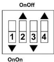
Fig 5-4: DIP Switch to Control Mic & Meter Features
Using the LF Filter
This switch provides control for a high pass filter on the mic input with low frequency roll off at 125Hz. The roll-off filter is in circuit when the switch is down (towards the arrow).
Compression Active on Mic Input Only
With this feature enabled, the compressor/limiter will only operate when the microphone input is selected. This mode becomes active when switch 3 is down (towards the arrow).
Peak Hold Disabled on LED Meter
By default, the LED meter operates with peak hold active on the top 5 segments. This can be disabled by moving switch 4 to the up position (towards the arrow).
Stereo Line Input
The 2 x XLR 3 pin sockets used for the line input are electronically balanced. They have the following connections:
Pin 1: Screen
Pin 2: Phase
Pin 3: Non-phase
Stereo Input Gain Pad
The line input channel with the volume control fully up, has a gain of +6dB. An extra 10dB of gain is available by depressing the rear panel INPUT LEVEL switch. The LINE VOLUME control is located on the front panel.
Stereo Line Output
The XLR 3 pin plug output connectors are electronically balanced and can be wired unbalanced by grounding the non-phase signal, allowing you to feed balanced and unbalanced equipment. They have the following connections:
Pin 1: Screen
Pin 2: Phase
Pin 3: Non-phase
The connector provides a line level output with an impedance of <50Ω and a maximum output level of +28dBu.
Stereo Output Gain Pad
The output gain switch provides a 10dB drop in gain.
5 Mixers, Source Selectors & Switchers - RB- SSML1
Front Panel Controls
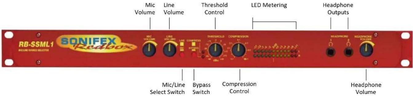
Fig 5-5: RB-SSML1 Front Panel
Mic & Line Volume Controls
The front panel MIC VOLUME reduces the volume to -80dB. The line input channel with the LINE VOLUME control fully up, has a gain of +6dB.
Mic/Line Select Switch
To select between microphone or stereo line inputs, use the Mic/Line select switch; stereo line is in the up position.
Bypass Button
The compressor/limiter section of the product can be switched in and out by using the BYPASS button.
Applying Compression
Compression is applied by setting a threshold at which the compressor begins to operate, and a compression ratio to which all audio above the threshold will be compressed. To enable the compressor, release the unit from bypass mode (ensure the bypass LED is off).
The compression ratio and threshold limits of the compressor/limiter section are fully adjustable via the COMPRESSION and THRESHOLD linear
pots situated on the front panel. The threshold can be set between -30dBu and +20dBu. When the input signal rises above the threshold level a soft-knee compression is applied at the selected ratio. The compressor has an attack time of approximately 20ms and a release time of approx 400ms, and can operate at ratios of 1:1 (no compression) to ∞:1 (limiting).
The compressor is temperature sensitive and in cold conditions may take a short time for the threshold levels to settle. In any case you should always allow the unit to fully come to its normal operating temperature before setting the threshold level.
LED Metering
The metering is carried out after the compressor/limiter section and consists of two rows of 12 round LEDs showing levels between -17dB and +11dB.
The LED meter source can be set to either the output, or a mix of the output and the monitor input (i.e. the audio present on the headphones). The default setting is a mix of the output and monitor input. This can be changed by altering the setting of jumpers J1 and J2 inside the unit.
Mixers, Source Selectors & Switchers - RB- SSML1
Position A: Meter a mix of output and monitor input.
Position B: Meter output only.
Headphone Outputs
There are two 1/4 " stereo jack headphone sockets, with a headphone output volume control which controls the volume for both outputs. Each headphone output is designed to drive 150mW into 32Ω to 600Ω stereo headphones.
Technical Specifications RB-SSML1
Audio Specifications (Bypass Mode)
| Maximum Input Level: -10dBu (mic), +28dBu (line), electronically balanced |
Input Impedance: 20kΩ nominal balanced
Maximum Output Level: +28dBu
Output Impedance: <50Ω
Headphone Output Level: Drives 150mW into 32Ω to 600Ω headphones
Low Frequency Roll-Off: 125Hz @ 6dB/octave
Gain Range (mic): Adjustable 36dB to 75dB gain (-80dB volume min.)
Volume Control (line): -80dB to +6dB gain (+16dB with additional input gain)
E.I.N: 130dB
Distortion: <0.02% THD @ 1kHz, ref +8dBu output
Common Mode Rejection:>66dB typically
Phantom Power: 48V
Frequency Response: 20Hz to 20kHz ±0.3dB (600Ω load, ref 1kHz)
Connections
Mic Input: 1 x XLR 3 pin female (Balanced)
Stereo Line Input: 2 x XLR 3 pin female (Balanced, can be
| unbalanced) | |
| Stereo Monitor Input: 2 x XLR 3 pin female (Balanced, can be unbalanced) | |
| Stereo Output: 2 x XLR 3 pin male (Balanced, can be unbalanced) | |
| Headphone Outputs: | 2 x 1⁄4" (6.35mm) A/B gauge 3-pole stereo jack sockets |
| Mains Input: | Filtered IEC, 110V-120V, or 220-240V switchable, fused, 9W maximum |
| Fuse Rating: | Anti-surge fuse 100mA 20 x 5mm (230VAC) Anti-surge fuse 250mA 20 x 5mm (115VAC) |
Equipment Type
RB-SSML1:

Mic/Line source selector with compressor limiter
Physical Specifications
| Dimensions (Raw): | 48cm (W) x 10.8cm (D) x 4.2cm (H) (1U) |
| 19" (W) x 4.3" (D) x 1.7" (H) (1U) |
| Dimensions (Boxed): | 53cm (W) x 20.5cm (D) x 6cm (H) |
| 21" (W) x 8" (D) x 2.4" (H) |
| Weight: | Nett: 1.3kg | Gross: 2.0kg |
| Nett: 2.9lbs | Gross: 4.4lbs |
6 Mixers, Source Selectors & Switchers - RB-OA3
6 RB-OA3 3 Studio On-Air Switcher

Fig 6-1: RB-OA3 Front Panel
The RB-OA3 is a 1U rack-mount, unity gain on-air switcher, capable of switching three stereo pairs between three studios. Each studio can control the transmission path together with two peripheral paths for equipment such as a codec or hybrid and there is also a last studio to offer (LSO) bus, allowing for seamless and continuous broadcast from any multi-studio radio network. A sustain mode allows for a sustaining system, such as a PC automation system, to control the broadcast. Multiple RB-OA3 units can be connected together to switch more studios or more stereo pairs.
The switching is achieved using relays, except the last studio to offer which is switched by an analogue switch. The transmission path is switched using latching relays. This means that if there is a power failure to the unit, the transmission path will remain selected.
All studios are connected using 25 way D-types for electronically balanced audio signals and control is achieved using 15 way D-types, connecting to an external control unit such as the Sonifex S2-MTBS mixer control panel or the RB-OA3R remote switcher panel.
A transmission mix connection is included to mix into the transmission path audio which is generic to all studios. This could be used for jingles or
adverts for example. The RB-OA3 also allows for the control of a profanity delay to be shared by all connected studios.
Each studio has the ability to offer the transmission. Once offered, the transmission is fed to the other studios via the last studio to offer bus. By adding the LSO bus as an input to the mixer, the next scheduled station can then fade in the transmission and accept at the appropriate time meaning the transmission can be continuous.
The sustain mode can be used to control an automated studio, such as a PC based overnight music system which conventionally wouldn't be in its own studio and would therefore need external control to take transmission back from it. Think of it as a studio which has no Offer and Accept controls of its own, but which can still be put to and from transmission by the other studios.
The RB-OA3 can be expanded to switch between up to 5 studios or up to 6 stereo pairs by connecting a multiple of units together. With the addition of a single unit, expansion in studio mode allows for 2 additional studios to take control of the transmission path and additional equipment. If the expansion is made in bus mode, then three additional stereo channels can
be added. In total 4 x RB-OA3 units can be connected together to switch 6 stereo pairs between up to 5 studios. An optional cable kit, the RB-OA3C, is available to connect expansion RB-OA3 units to a master RB-OA3.
The modes are configured by dip switches on the rear of each unit. Two dip switches control the unit ID and two switches control whether the unit is in studio or bus mode.
A master unit, defined by a preset ID, conducts all communication between all units.
System Block Diagram
![graph TD Studio1["Studio 1"] --> DipSwitch["Dip Switch"] Studio2["Studio 2"] --> LSOFeeds["LSO Feeds"] Studio3["Studio 3"] --> LSOFeeds ControlPanls1["Control Panels 1"] --> DipSwitch ControlPanls2["Control Panels 2"] --> DipSwitch ControlPanls3["Control Panels 3"] --> DipSwitch DipSwitch --> Proces…](/content/2026/06/1225749/images/f10f378ea5e18a054ed8ff75a5de8a04a85f7f1003b3d9ed488d02789e939c90.jpg)
Fig 6-2: RB-OA3 System Block Diagram
6 Mixers, Source Selectors & Switchers - RB-OA3
Rear Panel Connections and Operation
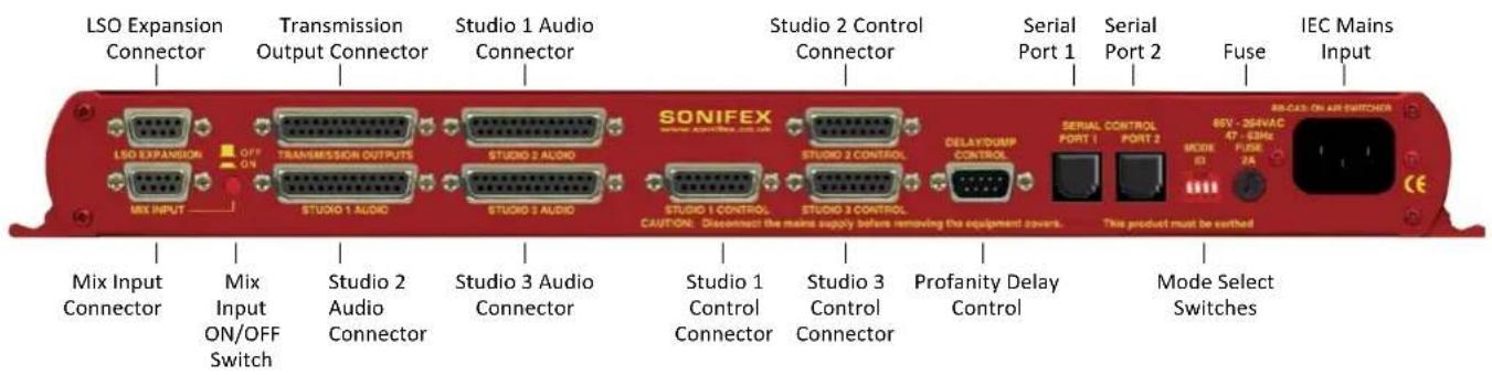
Fig 6-3: RB-OA3 Rear Panel
Installation Guide for the RB-OA3
Setting the Unit's Identity Using The Mode ID DIP Switches Multiple RB-OA3 units can be combined to offer expansion of either the number of studios (STUDIO EXPANSION), or the number of stereo audio pairs available to switch (BUS EXPANSION), or both (STUDIO & BUS EXPANSION). Up to 4 units can be connected together and each unit will have a different Mode ID.
The identity of the unit is defined by setting the first two MODE ID DIP switches as per the following table:
| DIP Switch 1 DIP Switch 2 Unit Identity Definition | |
| OFF OFF MASTER | |
| ON OFF STUDIO EXPANSION SLAVE | |
| OFF ON BUS EXPANSION SLAVE | |
| ON ON STUDIO & BUS EXPANSION SLAVE | |
Fig 6-4: RB-OA3 Unit Identity Definitions
If you have just a single RB-OA3, define it as the MASTER, i.e. DIP switches 1 and 2 set to OFF. For more information on the expansion modes, see page 46.
If you would like to change the identity of a unit, it will have to be reset.
Note: The recommended time to change the unit ID is on power down.
Setting The Boot Up Mode
On first powering up the RB-OA3, the unit will default to giving transmission control to Studio 1. The third DIP switch controls what studio the unit will boot to on subsequent initialisations. The different modes provided are:
| OFF This will | set the unit to Force Last Used Studio mode |
| ON This will | set the unit to Force Studio 1 mode |
Fig 6-5: RB-OA3 Unit Identity Reset Settings
Force Last Used Studio Mode
When a studio is selected, the value of that studio is stored in the unit. This is then recalled on boot up so that the last studio to transmit is reconnected. This is useful in loss of power situations, since the latching relays will remain in position on start up, leaving the transmission path unaffected.
Force Studio 1 Mode
On boot up Studio 1 is given transmission control. This is useful for returning the unit to a known position.
Note: When connecting multiple units together ensure that there is only one of each type of unit. If you connect units of the same type, communication errors will occur. For security, once initialized, the unit will retain its ID until power down regardless of any DIP switch changes.
Configuring for Operation
The RB-OA3 can be used in both single (MASTER) and multiple expansion modes.
Single (MASTER) Mode
When used as a single (MASTER) unit, the RB-OA3 is used to switch 3 stereo buses between 3 studios, allowing them to share the same transmission path and peripheral devices such as hybrids or profanity delays. A single unit must always be configured as a MASTER unit.
Studio Connections
Each connector has a dedicated channel for the master transmission and for each of the two additional balanced stereo channels. The connector also provides the Last Studio to Offer (LSO) feed. The Transmission path is a latched pathway so that it will remain even if there is no power supply. For this reason, the transmission output of your mixer should always be routed to this channel. The peripheral channels are non-latching.
Control Panels
Connect the chosen control panels, such as an RB-OA3R, one to each STUDIO CONTROL port. The control ports are designed to allow 200mA at 15V from each chosen connector.
An excess will cause a polyfuse to cut the voltage supply which can be reset by removing the load.
Profanity Delay Connector
You can control a profanity delay connected to the unit. The control pulses are relay based and can be wired either normally open or normally closed, to route a common signal.
Mix Input
If the mix input is to be used, connect the source to the unit. If not, the socket must be terminated, or the MIX INPUT ON/OFF switch must be OFF, otherwise the output signal may experience a loss of level (see page 53).
LSO Expansion Port
Leave disconnected.
Serial Ports
Leave these disconnected.
6 Mixers, Source Selectors & Switchers - RB-OA3
DIP Switch Settings
Studio Expansion
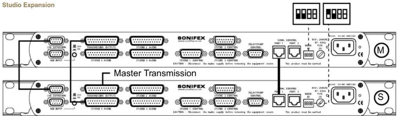
Fig 6-6: RB-OA3 Studio Expansion Diagram
Connect two units to allow the switching of 3 stereo buses between 5 studios giving the user control over more studios. To achieve this configure one unit as the MASTER and one unit as the STUDIO EXPANSION:
Studio Connections
Connect three studios to the master unit and connect the MASTER RB-OA3 TRANSMISSION OUTPUT to the STUDIO 1 AUDIO input of the STUDIO EXPANSION RB-OA3 using a transmission expansion cable (available in the RB-OA3C cable pack). Then connect studios 4 and 5 to the STUDIO 2 AUDIO and STUDIO 3 AUDIO connectors on the STUDIO EXPANSION SLAVE unit. The TRANSMISSION OUTPUTS port of the STUDIO EXPANSION unit is the main output of this system.
Control Panels
Connect three control panels to the MASTER STUDIO CONTROL PORTS 1 - 3, one for each studio. The control panels for studio 4 and 5 need to be connected to the STUDIO 2 CONTROL and STUDIO 3 CONTROL ports of the STUDIO EXPANSION unit.
Profanity Delay Connector
A profanity delay can be connected to either of the two units. However, it is recommended that it is connected to the MASTER. See Single (MASTER) Mode set up for more information.
Mix Input
The mix input must be connected to STUDIO EXPANSION unit to ensure that the mix input is on all five studios. Ensure that the MASTER mix input is terminated correctly or that the MIX INPUT ON/OFF switch is OFF.
LSO Expansion
The LSO feed needs to travel between the units. Do this by connecting the LSO expansion ports on each unit with an LSO expansion cable (available in the RB-OA3C cable pack).
Serial Ports
Connect the serial ports of the MASTER and STUDIO EXPANSION units together using a standard RJ45 network cable (available in the RB-OA3C cable pack).
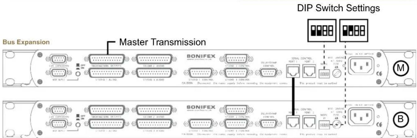
Fig 6-7: RB-OA3 Bus Expansion Diagram
Connect two units to allow the switching of 6 stereo buses between 3 studios so that the studios can share more peripheral devices. To achieve this configure one unit as the MASTER and one unit as the BUS EXPANSION SLAVE:
Studio Connections
Connect three studios to the MASTER unit and connect the MASTER TRANSMISSION OUTPUT to your transmission output destination. The BUS EXPANSION SLAVE switches as the MASTER.
To access the three extra balanced stereo channels, connect to the transmission and peripheral paths of the BUS EXPANSION SLAVE STUDIO 1-3 AUDIO connectors. The outputs for these paths will be the TRANSMISSION OUTPUT of the BUS EXPANSION SLAVE.
Control Panels
Connect three studio control panels to the MASTER STUDIO CONTROL PORTS 1 - 3, one for each studio. If control panels are connected to the BUS EXPANSION SLAVE the LEDS will simply follow the master control panels, however no action can be initiated with a slave control panel.
Profanity Delay Connector
A profanity delay can be connected to either of the two units. However, it is recommended that it is connected to the MASTER. See Single (MASTER) Mode set up for more information.
Mix Input
The mix input must be connected to the MASTER. Because it's not being used, ensure that the BUS EXPANSION SLAVE mix input is terminated correctly or that the MIX INPUT ON/OFF switch is OFF for this SLAVE.
LSO Expansion
Leave disconnected on both units.
Serial Ports
Connect the serial ports of the MASTER and BUS EXPANSION SLAVE units together using a standard RJ45 network cable (not a cross-over cable).
6 Mixers, Source Selectors & Switchers - RB-OA3
Studio & Bus (4 Unit) Expansion
DIP Switch Settings DIP Switch Settings
![graph TD subgraph Module_M A["800PROM"] -->|Data Bus| B["800PROM"] C["800PROM"] -->|Data Bus| D["800PROM"] E["800PROM"] -->|Data Bus| F["800PROM"] G["800PROM"] -->|Data Bus| H["800PROM"] I["800PROM"] -->|Data Bus| J["800PROM"] K["800PROM"] -->|Data Bus| L["800PROM"] M["800PROM"] -->|Data Bus| N["800…](/content/2026/06/1225749/images/61e049c6d7f3b4645524e4acb5e45e0c1d23ba199f10928d85e0dd42ee9c440e.jpg)
Fig 6-8: RB-OA3 Studio & Bus Expansion Diagram
Connect two units to allow the switching of 6 stereo buses between 3 studios allowing the studios to share more peripheral devices. To achieve this configure one unit is set as the MASTER, one unit as the STUDIO EXPANSION SLAVE, one unit as the BUS EXPANSION SLAVE and one unit as the STUDIO & BUS EXPANSION SLAVE:
Studio Connections
Connect the STUDIO EXPANSION SLAVE and the BUS EXPANSION SLAVE as shown previously to give you a system of three units. The STUDIO & BUS EXPANSION SLAVE is added as a bus expansion for studios 4 and 5. To connect this unit, use a second transmission connection cable to connect the TRANSMISSION OUTPUT of the BUS EXPANSION SLAVE with the STUDIO 1 AUDIO connector of the BUS EXPANSION SLAVE. The TRANSMISSION OUTPUT from the BUS EXPANSION SLAVE acts as the I/O for all the bus expansion paths.
Control Panels
Connect three control panels to the MASTER STUDIO CONTROL PORTS 1 - 3, one for each studio. The control panels for studio 4 and 5 need to be connected to STUDIO CONTROL PORTS 2 and 3 of the STUDIO EXPANSION. There is no need to connect control panels to the BUS EXPANSION SLAVE and STUDIO & BUS EXPANSION SLAVE although, if connected, they will reflect the situation shown by the control panels connected to the MASTER and STUDIO EXPANSION SLAVE units.
Profanity Delay Connector
A profanity delay can be connected to either of the four units. However, it is recommended that it is connected to the MASTER. See Single (MASTER) Mode set up for more information.
Mix Input
The mix input must be connected to the STUDIO EXPANSION SLAVE to ensure that the mix input is on all five studios. Ensure that the MASTER mix input is terminated correctly or that the MIX INPUT ON/OFF switch is OFF (see page 53).
LSO Expansion
The LSO feed needs to travel between units. This is achieved by connecting the LSO expansion ports on the MASTER and STUDIO EXPANSION with an LSO expansion cable (available in the RB-OA3C cable pack). For the BUS EXPANSION SLAVE and STUDIO & BUS EXPANSION SLAVE, there is no need to connect the LSO expansion cables since the LSO is not used in bus expansion.
Connect the serial ports of the MASTER and all the SLAVE units together using a standard RJ45 network cable. It is recommended that a full ring system is implemented by connecting each unit to two others.
This ensures that if one connection is lost, there is still a path for communication for each unit. If the decision is taken to use three cables rather than four, please ensure that there is a direct link between the MASTER and STUDIO EXPANSION SLAVES.
![graph TD A["Serial Ports"] --> B["RB-OA3 1 RB-OA3 2"] B --> C["RD-04"] C --> D["RD-OA3 4 RB-OA3 3"] D --> E["RD-OA3 5"] style A fill:#f9f,stroke:#333 style B fill:#ccf,stroke:#333 style C fill:#cfc,stroke:#333 style D fill:#fcc,stroke:#333 style E fill:#ffc,stroke:#333](/content/2026/06/1225749/images/1ee852939df1fbe5d70bbcdce6ca80c58fd13d8db05960ac438f55982b07d9d2.jpg)
Fig 6-9: RB-OA3 Multiple RB-OA3 Expansion Diagram
6 Mixers, Source Selectors & Switchers - RB-OA3
Indications – How The LEDS Are Used
FRONT PANEL LEDS
The unit is supplied with 7 LEDs on the front panel. These LEDs are used to indicate all the various states of the unit:
POWER
This LED is used to indicate whether the unit is currently powered. It is illuminated RED if the unit is powered and extinguished if not.
DELAY
This LED is used to show whether the Delay function has been activated. Its operation is momentary and each burst will last for approximately half a second. If the button is illuminated RED this means that the delay pulse has been activated.
DUMP
This LED is used to show whether the Dump function has been activated. Its operation is momentary and each burst will last for approximately half a second. If the button is illuminated RED this means that the dump pulse has been activated.
OFFER
This LED is used to show whether the system is currently in OFFER mode. This LED is illuminated YELLOW while the unit is on offer and extinguished otherwise. If this LED flashes this means that the unit is currently in SUSTAIN ACTIVE mode (see page 51).
STUDIO 1-3
These LEDs are used to indicate which studio is currently switched to the transmission path. Each one is illuminated RED to represent each specific studio when that studio is switched in. When the unit is operating as a
STUDIO EXPANSION SLAVE, if one of the MASTER unit's studios is routed to the transmission path, STUDIO 1 LED will always be illuminated. If one of SLAVE'S studios is selected, the MASTER unit's studio indications will all be extinguished.
CONTROL PANEL LEDS
Each of the control panel connectors has the ability to switch on four LEDS. In the case of the S2-MTBS and the RB-OA3R, the LEDS are built into the buttons.
OFFER
This LED is used to show whether the system is currently in OFFER mode. This LED is illuminated while the unit is on offer and extinguished otherwise. If this LED flashes this means that the unit is currently in SUSTAIN ACTIVE mode.
ACCEPT
This LED is illuminated if the studio is currently on the transmission path. In SUSTAIN ARMED mode this LED will flash repeatedly until the specific studio is selected. The ACCEPT LED will always flash to indicate SUSTAIN ARMED mode.
DELAY
This LED is used to show whether the studio has activated a delay pulse. It is illuminated when a delay pulse is activated.
DUMP
This LED is used to show whether the studio has activated a dump pulse. It is illuminated when a dump pulse is activated.
EMERGENCY MODE
If the MASTER loses contact with any of the SLAVES, the SLAVES will enter emergency mode. In emergency mode all the LEDS except the power led will flash repeatedly until contact with the master is re-established.
Operational Modes
OFFER
If a studio is transmitting, this mode is used to offer the transmission path to other studios. When the OFFER button is pressed, the OFFER button in all studios is illuminated. This unlocks the operation of the ACCEPT button in all other studios. To remove this mode, simply press the OFFER button again. Pressing this also switches the current studio to the LSO bus.
ACCEPT
This mode is used to accept the transmission path. To do this, press the ACCEPT button once the offer has been made. Once the studio has accepted, this switches the OFFER, DELAY, DUMP and SUSTAIN functions to that studio.
SUSTAIN
This mode is used to switch to a sustaining service, for example, a PC automation system, which conventionally wouldn't be in its own studio and would therefore need external control to take transmission back from it. Think of it as a studio which has no Offer and Accept controls of its own, but which can still be put to and from transmission by the other studios.
The sustain studio is Studio 3 by default and this cannot be changed. Once the sustain function is activated, the transmission path switches instantly to Studio 3 and is automatically offered back to all studios. To enter SUSTAIN mode, press the OFFER button to enter offer mode then hold the ACCEPT button for three seconds. DELAY and DUMP modes are inactive in SUSTAIN.
The SUSTAIN mode has two phases:
SUSTAIN ACTIVE
In this phase, studio 3 is transmitting and the offer is made to all studios. The offer button flashes in all studios to let the controllers know that the sustain mode is active. To retrieve the control, a studio must press the flashing OFFER button. SUSTAIN mode then enters phase 2, SUSTAIN ARMED.
SUSTAIN ARMED
In this phase, a studio is ready to take control. The OFFER button is constantly lit in the studio that triggered this phase and the ACCEPT will flash in both the arming studio and Studio 3. In the other studios, all the buttons will be inactive and the LEDS will all be off.
The arming studio can now accept the transmission path by pressing the ACCEPT button. If the arming studio wants to return the unit to SUSTAIN ACTIVE phase, the OFFER button should be pressed.
DELAY/DUMP
These functions are used to control a profanity delay. To use these functions route the transmission to the delay unit control input and setup the delay unit accordingly. The output is then taken from the delay unit. The unit has both a normally closed and normally open relay trigger. When the DELAY or DUMP button is pressed, a half second pulse triggers the specific relay which will either connect to, or break, the connection with a Common signal (supplied from the delay unit).
EMERGENCY
In the multiple unit cases there is an EMERGENCY mode. This mode is activated with the SLAVE units to alert the user that communication with the MASTER has broken down. In this mode, all LEDs associated with the unit will start flashing (except the POWER LED).
While the unit is in this mode it will not respond to any commands. Once the unit re-establishes a connection with the MASTER, the unit will return to the position it was in prior to the disconnection, if the MASTER is unchanged, or it will update if the MASTER has changed. As an extra safety feature, if the STUDIO EXPANSION SLAVE loses communication while studio 4 or 5 is transmitting, the MASTER will lock all ability to change transmission studio until contact is re-established. If the MASTER loses power or all communication paths, all SLAVES will display emergency mode. In addition if any SLAVE loses power it will automatically reboot into the correct state.
6 Mixers, Source Selectors & Switchers - RB-OA3


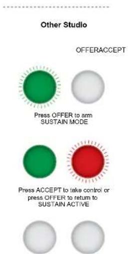
Rear Panel Connections & Operation
LSO Expansion
The connector is 9 a pin female D-type and is used to transfer the last studio to offer channel between units, when used in multiple unit mode.
LSO Expansion Connector Details
| 1 LSO Input Left Phase |
| 2 LSO Input Right Phase |
| 3 LSO Output Left Phase |
| 4 LSO Output Right Phase |
| 5 Analogue Ground |
| 6 LSO Input Left Non Phase |
| 7 LSO Input Right Non Phase |
| 8 LSO Output Left Non Phase |
| 9 LSO Output Right Non Phase |
Fig 6-11: RB-OA3 LSO Expansion Connector Definitions
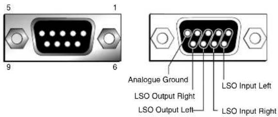
Fig 6-12: RB-OA3 LSO Expansion Connector Details
Fig 6-10: Offer & Accept Button Operation (Flashing is indicated by radial lines around a button)
Mix Input Selection
The interface is a 9 pin female D-type and is used to mix a stereo feed into the transmission path by using the MIX INPUT ON/OFF SWITCH, push button (rear panel, located next to the mix input). This could be an emergency announcement system, PC automation playout system, or other audio source.
Note: If this input is not being used it must either be switched off using the push-button, or terminated by connecting pins 2 & 7 together and pins 4 & 9 together. If it is not terminated the noise on the transmission output can be worse by 3-6dB.
Mix Input Connector Details
| 1 Mix Input Right Phase |
| 2 Mix Input Right Non Phase |
| 3 Mix Input Left Phase |
| 4 Mix Input Left Non Phase |
| 5 NC |
| 6 Analogue Ground |
| 7 Impedance Connection |
| 8 Analogue Ground |
| 9 Impedance Connection |
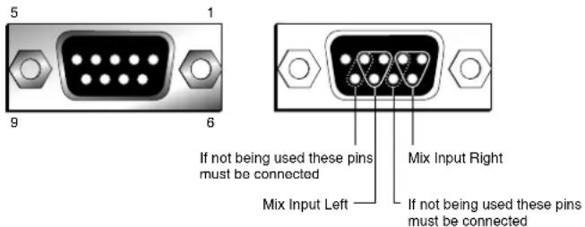
Fig 6-14: RB-OA3 Mix Input Connector Details
Transmission Outputs and Studio 1-3 Audio Connection Details There are three studio interfaces to connect three individual studios to the unit. There is also a transmission interface which carries the main transmission output and 2 balanced stereo connections for interfacing with external units such as hybrids, or codecs, which you may want to share between studios. These are all 25 way female D-Types and they each carry 4 balanced stereo pairs or 8 mono.
Fig 6-13: RB-OA3 Mix Input Connector Definitions
6 Mixers, Source Selectors & Switchers - RB-OA3
Transmission Outputs I/O Connector Details
| 1 Transmission Left Phase (Output) | |
| 3 Transmission Right Non Phase (Output) | |
| 4 | 1st external unit Left Phase (Input/Output) |
| 6 | 1st external unit Right Non Phase (Input/Output) |
| 7 | 2nd external unit Left Phase (Input/Output) |
| 9 | 2nd external unit Right Non Phase (Input/Output) |
| 14 Transmission Left Non Phase (Output) | |
| 15 Transmission Right Phase (Output) | |
| 17 1 | st external unit Left Non Phase (Input/Output) |
| 18 1 | st external unit Right Phase (Input/Output) |
| 20 2 | nd external unit Left Non Phase (Input/Output) |
| 21 2 | nd external unit Right Non Phase (Input/Output) |
All other pins are analogue ground.
Fig 6-15: RB-OA3 Transmission I/O Connector Definitions

Fig 6-16: RB-OA3 Transmission Outputs Connector Details
Studio 1-3 Audio Connection Details
| 1 Transmission Left Phase (Input) | |
| 3 Transmission Right Non Phase (Input) | |
| 4 | 1st external unit Left Phase (Input/Output) |
| 6 | 1st external unit Right Non Phase (Input/Output) |
| 7 | 2nd external unit Left Phase (Input/Output) |
| 9 | 2nd external unit Right Non Phase (Input/Output) |
| 10 Last Studio to Offer Left Phase (Output) | |
| 12 Last Studio to Offer Right Non Phase (Output) | |
| 14 Transmission Left Non Phase (Input) | |
| 15 Transmission Right Phase (Input) | |
| 17 1 | st external unit Left Non Phase (Input/Output) |
| 18 1 | st external unit Right Phase (Input/Output) |
| 20 2 | nd external unit Left Non Phase (Input/Output) |
| 21 2 | nd external unit Right Phase (Input/Output) |
| 23 Last Studio to Offer Left Non Phase (Output) | |
| 24 Last Studio to Offer Right Phase (Output) | |
All other pins are analogue ground.
Fig 6-17: RB-OA3 Studio 1-3 Audio Connector Definitions
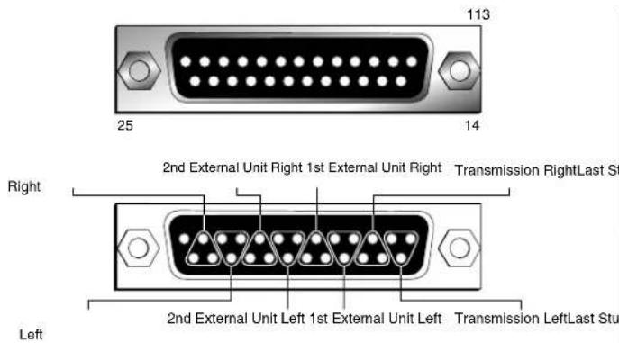
Fig 6-18: RB-OA3 Studio 1-3 Audio Connector Details
Studio 1-3 Control Port Connection Details
Each studio can be controlled externally via the optional RB-OA3R rack control system or, if the studio uses the Sonifex S2 mixer, the S2-MTBS panel which can be connected to the unit via these control ports. Each control panel enables control of the Offer, Accept and Sustain functions as well as Dump and Delay.
There is a pin for each function which needs to be pulled low to activate the function.
There is also a pin that becomes grounded once that function is selected. This is so that an
indicator such as a tally LED can be used. There is also a Digital Ground and 15V supply.
The connectors are 15 pin Female D-types.
| 1 15V |
| 2 Offer Signal Input |
| 3 Offer LED |
| 4 Accept Signal Input |
| 5 Accept LEDAudio to Offer |
| 6 Delay Signal Input |
| 7 Delay LED |
| 8 Dump Signal Input |
| 9 Dump LEDAudio to Offer |
| 15 Digital Ground |
All other pins are unused.
Fig 6-19: RB-OA3 Studio 1-3 Control Connector Definitions
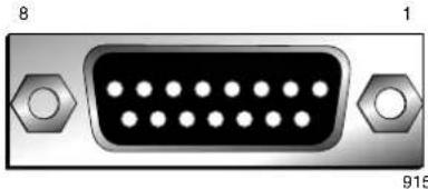
![graph LR A["For Switch Control"] --> B["Offer, accept, delay or dump Signal Input"] B --> C["Momentary switch"] C --> D["GND (Pin 15)"] E["For Lamp Control"] --> F["15V (Pin 1) or Own Voltage Source"] F --> G["Lamp Circuitry"] G --> H["Offer, accept, delay or dump LED"]](/content/2026/06/1225749/images/dca55f11eb81d9e87853dde702d684f1030fded4899ac911d620d96b7d86ae3e.jpg)
Fig 6-20: RB-OA3 Switch & Lamp Control Details
6 Mixers, Source Selectors & Switchers - RB-OA3
Profanity Delay Control
A profanity delay unit can be attached and controlled to the unit via this interface. The control is achieved using a relay. Each relay has a common input pin and two possible output pins (open or closed). The relay can then be configured to route the applicable voltage to its output pins. For example for an active low triggered input, 0V would be connected to the relevant Common pin and the profanity delay input pin would be connected to the Normally Open pin of the relay.
The interface is a 9 pin male D-type.
| 1 Digital Ground |
| 2 NC |
| 3 Delay Normally Closed Output |
| 4 Dump Relay Common |
| 5 Dump Normally Open Output |
| 6 NC |
| 7 Delay Relay Common |
| 8 Delay Normally Open Output |
| 9 Dump Normally Closed Output |
Fig 6-21: RB-OA3 Profanity Delay Control Connector Definitions
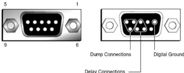
Fig 6-22: RB-OA3 Profanity Delay Control Connector Details
Serial Ports
There are two parallel serial ports on the back of each unit to enable the connection of multiple RB-OA3 units. These use standard RJ-45 connectors.
When connecting multiple RB-OA3 units together, simply connect these ports together.
If you have more than two RB-OA3 units, multiple connections can be made to ensure that all units communicate even if one connection is lost.
Connecting an RB-PD2 Profanity Delay to the RB-OA3 Switcher If you wish to use the RB-OA3 with an RB-PD2 then this unit requires an active low signal i.e the input pin must be linked to ground. This means that both pins 4 and 7 on the RB-OA3 should be linked to ground on the RB-PD2 remote port in order to control it. The 'Normally Open' output would then be used to trigger dump or delay.
The RB-PD2 has the following connections:
Pin 1: Active low input 1
Pin 2: Active low input 2
Pin 3: Active low input 3
Pin 4: Active low input 4
Pin 5: Active low input 5
Pin 6: Active low input 6
Pin 7: Active low input 7
Pin 8: Active low input 8
Pin 9: Signal ground
Pin10: Open collector output 1
Pin11: Open collector output 2
Pin12: Open collector output 3
Pin13: Open collector output 4
Pin14: Open collector output 5
Pin15: Open collector output 6
The RB-PD2 is configured so that the input pins on the remote port can represent any function on the units front panel. In order to use the dump and delay control from the RB-OA3, two of the inputs must be set to be Build Delay and Activate Dump respectively. These settings are accessed from the Remotes:Configure Inputs: menu option. For example if you wanted to use input 1 on the RB-PD2 as Delay and input 2 as Dump, then this would be achieved by selecting the applicable input under Remotes:Configure Inputs and changing the setting on the RB-PD2. The interconnections would then be as indicated below:
| Signal PD2 Pin OA3 Pin | ||
| Delay 1 8 | ||
| Dump 2 5 | ||
| Ground 9 4 and 7 |
Technical Specifications RB-OA3
LSO Path:
Input Impedance: >20kΩ
Output Impedance: <50Ω
Gain Range: Unity gain
Frequency Response: 20Hz to 20kHz ±0.1dB
Common Mode Rejection: < -52dB typically
Distortion: 0.01%THD @ 1 kHz
Noise: \~ -87dB unity gain, ref +8dBu
Mix Audio Transformer Specifications:
Common Mode Rejection: < -64dB @ 10kHz
Distortion: 0.5% THD ref 17dBu @ 40Hz
Bandwidth: ±0.5dBu 10Hz to 36kHz
Connections:
Studio Audio I/O: 3 x 25 way D type socket (female)
Transmission I/O: 1 x 25 way D type socket (female)
Dump/Delay Control: 1 x 9 way D type plug (male)
Studio Control: 3 x 15 way D type sockets (female)
LSO Expansion Port: 1 x 9 way D type socket (female)
Mix Input: 1 x 9 way D type socket (female)
Serial Ports: 2 x RJ45
Mains Input: Filtered IEC, 110V-120V, or 220-240V switchable, fused, 9W maximum
Equipment Type
RB-OA3: 3 studio on-air switcher

Physical Specification
| Dimensions (Raw): | 48cm (W) x 15.8cm (D) x 4.2cm (H) (1U) |
| 19" (W) x 6.2" (D) x 1.7" (H) (1U) | |
| Dimensions (Boxed): | 59cm (W) x 27.4cm (D) x 10.8cm (H) |
| 23.2" (W) x 10.8" (D) x 4.3" (H) | |
| Weight: | Nett: 1.9kg Gross: 2.5kg |
| Nett: 4.2lbs Gross: 5.5lbs |
7 Mixers, Source Selectors & Switchers - RB-OA3R
7 RB-OA3R Remote Switch Panel For RB-OA3
Introduction

Fig 7-1: RB-OA3R Front Panel
The RB-OA3 has been designed for installation in a central technical area with cabling to custom panels, or selection switches, in each studio. If you don't have any custom switch panels available, you can use an RB-OA3R in each studio. The RB-OA3R is a 1U rack mount switch unit for use in each studio that needs to be connected to the STUDIO 1-3 CONTROL connectors on an RB-OA3. It takes it's power from the RB-OA3 unit so needs no power supply itself.
It contains four buttons which are used to control the functions of the RB-OA3. Each front panel push button is illuminated by coloured LEDs and controls the OFFER, ACCEPT, DELAY and DUMP functions:
| Offer Green |
| Accept Red |
| Delay Yellow |
| Dump Yellow |
Fig 7-3: RB-OA3R Control Function Indication Colour
The connector on the rear of the RB-OA3R is a 15 way D type plug which connects to the Studio Control inputs on the RB-OA3.

Fig 7-2: RB-OA3R Rear Panel
The connections are as follows:
| 1 15V |
| 2 Offer Switch |
| 3 Offer Lamp |
| 4 Accept Switch |
| 5 Accept Lamp |
| 6 Delay Switch |
| 7 Delay Lamp |
| 8 Dump Switch |
| 9 Dump Lamp |
| 15 Ground |
Fig 7-4: RB-OA3R Pin Out Definitions
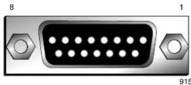
Fig 7-5: RB-OA3R Pin Out Positions
The 15V supply is fed through resistors to the LEDs. When any button is pressed, the switch links Ground to the switch pin of that specific button. When this is detected by the RB-OA3, it grounds the specific lamp pin, which grounds the LED, turning it on.
This unit connects directly to the RB-OA3 control panel interfaces using a pin to pin 15 way lead.
Technical Specifications RB-OA3R
Connections:
Studio Control: 1 x 15 way D type plug (male)
Equipment Type
RB-OA3R: Remote switch panel for RB-OA3

Physical Specification
Dimensions (Raw): 48cm (W) x 10.8cm (D) x 4.2cm (H) (1U) 19" (W) x 4.3" (D) x 1.7" (H) (1U)
Dimensions (Boxed): 53cm (W) x 20.5cm (D) x 6cm (H) 21" (W) x 8" (D) x 2.4" (H)
Weight: Nett: 1.2kg Gross: 1.8kg Nett: 2.6lbs Gross: 4lbs
8 Mixers, Source Selectors & Switchers - RB-OA3C
8 RB-OA3C Expansion Unit Cable Kit For RB-OA3
Introduction
If you add another RB-OA3 to an existing unit to expand either the number of buses or studios, you need additional cables to connect it which are contained in this kit:
1 x Transmission output expansion cable, 25 pin D-type male to 25 pin D-type male, 30cm lead, wired pin to pin.
1 x LSO expansion cable, 9 pin D-type male to 9 pin D-type male, 30cm lead, wired pin to pin.
1 x RS232 expansion cable, RJ45 to RJ45 standard wiring, 30cm lead.
1 x kit should be used for each expansion RB-OA3 being used.
Technical Specifications RB-OA3C
Equipment Type
RB-OA3C: Expansion unit cable kit for RB-OA3

9 RB-MM1 Mix Minus Generator
Introduction

Fig 9-1: RB-MM1 Front Panel.
Whenever programming originates from outside of the studio, or if listeners/viewers are calling up a phone-in using telephone hybrids or codecs, mix-minus feeds are required. Most telephone lines incur delays which prohibit off-air monitoring, because the caller, or remote talent, would hear their own voice in delay which is very disconcerting. The solution is to feed a mix back to the caller minus his or her own voice. Some mixing desks do not have a dedicated telco channel to generate a clean-feed, or mix minus, so the RB-MM1 can be used.
The RB-MM1 is a unit for generating a suitable mix to send to a telephone hybrid or codec. A stereo output is taken from a mixer, together with a post fader output from the mono telephone fader on the mixer. The caller audio is removed from the station output so that it can be sent to the telephone line via the hybrid.
Analogue audio inputs and outputs are via Neutrik XLR connectors. The output level to the TBU can be adjusted using a rear panel pre-set potentiometer. To control the cancellation null, 2 multi-turn potentiometers are provided, one for the LF null and the other for the full-band null. Additionally, a band pass filter can be switched in and out, via a rear panel switch, to condition the signal for the telephone hybrid. To use the RB-MM1 unit with full-band ISDN codecs, the band pass filter can be switched out. For stereo codecs, or conference calls, multiple RB-MM1 units can be used.
A red LED indicates when power to the RB-MM1 is on.
System Block Diagram
![graph LR A["Balanced Stereo Input From Mixer"] --> B["L"] C["Balanced Mono Input From Telephone Fader"] --> D["R"] B --> E["Σ"] D --> E E --> F["Filter Switch"] F --> G["Output Level"] G --> H["Bandpass Filter"] H --> I["Balanced Output To TBU"] style A fill:#f9f,stroke:#333 style C fill:#f9f,stroke…](/content/2026/06/1225749/images/60563e1676b613bdaadeecee50c47172d712ca1473330b8aa03cb595b2e16dc8.jpg)
Fig 9-2: RB-MM1 System Block Diagram
9 Talkback & Communications - RB- MM1
Front Panel Indicator
The LED on the front panel is normally red to indicate that power is present on the unit.
Rear Panel Connections and Operation
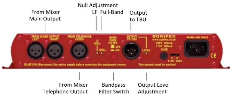
Fig 9-3: RB-MM1 Rear Panel.
Stereo Inputs From Mixer Main Output
These inputs should contain the main mixer output which will be a feed of the programme plus the audio that you want to remove by the mix-minus unit. Ideally, the input should be presented at 0dB. The XLR 3 pin sockets used for the left and right channel inputs are electronically balanced and have an impedance of greater than 10kΩ bridging. Each XLR has the following connections:
Pin 1: Screen.
Pin 2: Phase.
Pin 3: Non-phase.
Input From Mixer Telephone Fader
This mono input should contain the audio that needs to be removed by the RB-MM1, usually from the telephone/telco fader of a mixing console. Ideally, the input should be presented at 0dB. The XLR 3 pin socket used for the mono channel input is electronically balanced and has an impedance of greater than 20kΩ bridging. The XLR has the following connections:
Pin 1: Screen.
Pin 2: Phase.
Pin 3: Non-phase.
Output Null Adjustments (LF and Full-Band)
The 2 x null preset potentiometers are used to adjust the null between the input from the telephone fader and the main stereo input. The telephone input is made anti-phase and used to cancel out that signal in the main stereo signal. So, the nulls adjust the level of anti-phase signal required to achieve the best mix-minus null.
Band Pass Filter Switch
The band pass filter, when in the ON position, is used to limit the audio bandwidth of the output to the TBU between 200Hz and 4kHz. When using the RB-MM1 in full bandwidth equipment, e.g. for ISDN audio codecs, set this switch to the OFF position.
Output to Telephone Balance Unit (TBU)
The mono XLR 3 pin output plug connector is electronically balanced with an output impedance of less than 50Ω. It has the following connections:
Pin 1: Screen.
Pin 2: Phase.
Pin 3: Non-phase.
Output Level Adjustment
The TBU output gain can be adjusted from -15dB to +12dB, ref 0dBu by using the LEVEL preset potentiometer.
Operation of the RB-MM1
Before you receive your RB-MM1, it is calibrated at Sonifex by using two signals of equivalent amplitude and frequency. In some cases it may require recalibrating for use on a mixer to match the properties of that mixer. In order to do this make the following connections:
- Mixer left output to the RB-MM1 left input.
- Mixer right output to the RB-MM1 right input.
- Mixer post fade output from the relevant input channel (usually telco) to the RB-MM1 telephone fader input.
Then apply a signal to the input channel and raise the fader to its maximum level. To get the best results connect a level meter to the "Output to TBU" connector. Alternatively monitor the output acoustically and tune by ear.
Then adjust the NULL potentiometer until the output is as low as possible, if there is still some low frequency output adjust the LF NULL as well. The null available on this product is >40dB at 1kHz.
Technical Specifications RB-MM1
Audio Specification For RB-MM1
Maximum Input Level: +28dBu
Input Impedance: >20kΩ
Maximum Output Level: +28dBu
Output Impedance: <50Ω
Output Gain Range: Adjustable -15dB to +12dB, ref 0dBu gain via a multi-turn pot
Common Mode Rejection:>60dB
Band Pass Filter Range: 200Hz to 4kHz, 12dB/octave
LF Null Adjustment: Better than 40dB at 100Hz
Mix-Minus Null: Better than 40dB at 1kHz
Frequency Response: 20Hz - 22kHz ± 0.1dB
Distortion: 0.01% THD @ 1kHz, ref +8dBu output (C-Message weighted)
Noise: -90dBu unity gain, ref +6dBu
Connections
| Analogue Inputs From Mixer Output: | 2 x XLR 3 pin female (balanced) (L & R) |
| Analogue Input From | 1 x XLR 3 pin female (balanced) (L & R) |
| Telephone Fader: | |
| Analogue Output To TBU: 1 x XLR 3 pin male (balanced) (L & R) |
| Mains Input: | Filtered IEC, switchable 110-120V, or 220-240V, fused, 6W max. |
Fuse Rating: Anti-surge fuse 100mA 20 x 5mm (230VAC) Anti-surge fuse 250mA 20 x 5mm (115VAC)
9 Talkback & Communications - RB-MM1
Equipment Type
RB-MM1: Mix-minus generator

Physical Specification
Dimensions (Raw): 28cm (W) x 10.8cm (D) x 4.3cm (H) 11" (W) x 4.3" (D) x 1.7" (H)
Dimensions (Boxed): 36cm (W) x 20.5cm (D) x 6cm (H) 14.2" (W) x 8" (D) x 2.4" (H)
Weight: Nett: 1.1kg Gross: 1.5kg Nett: 2.4lbs Gross: 3.3lbs
10 RB-MTV1 Contribution Voiceover Monitor With Talkback
Introduction
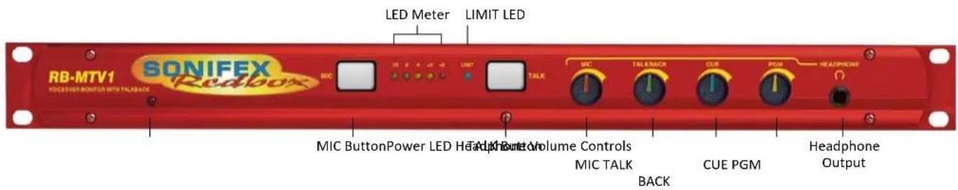
Fig 10-1: RB-MTV1 Front Panel
The RB-MTV1 contribution voiceover monitor is a 1U rack-mount designed to be used in voice-over booths, news booths, commentary locations, for continuity announcements and for any other similar applications where voice needs to be added to programme content and then monitored. Programme feeds, auxiliary feeds and a talkback feed can be taken in and monitored.
The RB-MTV1 has a microphone input, two main mono outputs, two external stereo monitoring inputs plus a 4-wire. It has a mono microphone input on XLR with switched coarse gain and variable fine gain control using a multi-turn preset potentiometer to give an overall gain range from +20dB to +80dB. There is also a switched LF rumble filter, switched +48V phantom power and switched level limiting control. A rear-panel multi-turn preset potentiometer allows adjustment of the threshold at which the limiter begins to operate, from -8dBu to +26dBu. There is an indication of the limiter activity using a blue LED and the microphone level is monitored by a simple 5 LED meter. The meter can be configured to either show the MIC signal activity in normal operation, i.e. when TALK is pressed the meter is off, or the meters can permanently show the MIC activity even when the TALK button is on or the MIC button is off.
There is a mono balanced TALKBACK input on XLR. There are two balanced XLR stereo inputs, CUE and programme (PGM) each with a 10dB input gain switch to facilitate the use of unbalanced sources such as from PC audio cards, domestic CD players, etc.
Each of these inputs, MIC, TALKBACK, CUE and PGM can be mixed and monitored in the front and rear headphone outputs with individual volume controls. Which of the inputs is presented to the headphone outputs can be configured using two banks of DIPswitches on the underside of the unit,
10 Talkback & Communications - RB- MTV1
one bank for audio that is heard in the left ear piece and one bank for audio monitored in the right ear piece. For example, the left and right PGM inputs can be sent to the right ear-piece and all other signals to the left ear-piece, or the TALK signal could be sent to the right ear-piece and all other signals to both ear-pieces. In this way, you can configure the unit for your particular application on installation. If a presenter doesn't like to hear themselves in their headphones when using the TALK button, there is also a DIPswitch option to mute the mic signal to the headphones.
There are two mono balanced outputs. The processed microphone signal is fed to the two outputs when the electronically latching front panel MIC button is active - the button illuminates when active.
The two main outputs can be independently switched to be at 'Line' or 'Mic' level outputs using rear panel push switches. Setting the output to a microphone level allows the unit to be inserted into the microphone channel of a mixer. There is an option to permanently enable the MIC
button, even when remotely controlled, for occasions when you always want the MIC channel left open. Additionally, there is an option to mix the CUE input as a mono feed to the outputs permanently.
The front panel TALK button is a momentary push switch that routes the processed microphone signal to the "LAZY" TALK output, whilst disconnecting it from the main outputs, allowing the operator to talk to a colleague. This enables the unit to be used as a talkback intercom between two or more studios.
There is a rear panel remotes connector giving remote control of the two front panel MIC and TALK buttons and opto-isolated tallies of their status.
A red LED on the front panel of the unit indicates when power is present.
System Block Diagram
![graph TD A["+48V"] --> B["Mic Input"] B --> C["Remotes"] C --> D["T/B Input"] D --> E["L"] E --> F["Cue"] F --> G["R"] G --> H["PGM"] H --> I["R"] I --> J["+10dB"] J --> K["Mic Meter"] K --> L["Left Headphone Mix"] K --> M["Right Headphone Mix"] L --> N["Headphone Front"] M --> O["Headphone Rear"] P…](/content/2026/06/1225749/images/6361f86a435b206bc0f2a7cdbeeb4afb4d4f40fa4e773b92fbae1847dfde516a.jpg)
Fig 10-2: RB-MTV1 Block Diagram
Front Panel Controls & Indicators
MIC Button
This is an illuminated electronically latching push switch that routes microphone audio to outputs 1 and 2, provided that the TALK button is not also pressed. The button illuminates red when the MIC function is active. Push the button again to unlatch it.
LED Meter
This is a 5 way LED meter with the following level indicators: -12dB (green), -6dB (green), 0dB (yellow), +3dB (yellow), +6dB (red). The LED meter source is selected by the back panel dip switch.
Limit LED
This 3mm blue LED illuminates when the limiter circuit is operating. A rear-panel multi-turn preset potentiometer allows adjustment of the threshold at which the limiter begins to operate, from -8dBu to +26dBu.
TALK Button
The TALK button is a momentary push switch that routes mic audio to the lazy talkback output, whilst disconnecting it from the main outputs, allowing the operator to talk to a colleague. The button illuminates green when the TALK function is active.

Fig 10-3: MIC Button

Fig 10-4: LED Meter
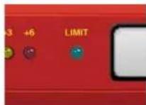
Fig 10-5: Limit LED

Fig 10-6: TALK Button
Headphone Level Controls
There are four volume control knobs, one for each of the audio sources MIC, TALKBACK, CUE and PGM, that determine the level of each audio source that is mixed into the front and rear panel headphone outputs.
As well as being able to alter the volume of the sources presented to the headphones, using DIPswitches on the underside, the RB-MTV1 can be configured to alter which of the inputs is presented to the headphone outputs, to enable customization of the unit for your monitoring application.

Fig 10-7: Headphone Level Controls
Headphone Output
The front panel headphone output is a 1/4" (6.35mm) jack socket and is a parallel connection of that on the rear, designed to drive 150mW into 32Ω to 600Ω professional headphones.
10 Talkback & Communications - RB-MTV1
Rear Panel Connections & Operation

Fig 10-8: RB-MTV1 Rear Panel Connections
Headphone Output
The rear panel headphone output is a 1/4" (6.35mm) jack socket and is a parallel connection of that on the front, designed to drive 150mW into 32Ω to 600Ω professional headphones.
Output 2 With Mic/Line Switch
The XLR 3 pin plug used for the mono mic/line output is electronically balanced and has an output impedance of <50Ω bridging in line mode and 100Ω nominal in mic mode. The XLR has the following connections:
Pin 1: Screen.
Pin 2: Phase.
Pin 3: Non-phase.
Depressing the MIC/LINE button converts the output to a mic level and impedance for insertion into a mic channel. The default state for this output is LINE.
Output 1 With Mic/Line Switch
The XLR 3 pin plug used for the mono mic/line output is electronically balanced and has an output impedance of <50Ω bridging in line mode and 100Ω nominal in mic mode. The XLR has the following connections:
| Pin | 1: | Screen. |
| Pin | 2: | Phase. |
Pin 3: Non-phase.
Depressing the MIC/LINE button converts the output to a mic level and impedance for insertion into a mic channel. The default state for this output is LINE.
TALKBACK (LAZY) Output
The XLR 3 pin plug used for the mono lazy talkback output is electronically balanced and has an impedance of < 50Ω bridging. The XLR has the following connections:
| Pin | 1: | Screen. |
| Pin | 2: | Phase. |
Pin 3: Non-phase.
This output is activated by pressing the "TALK" button on the front panel and is intended to be used as a talkback intercom between two units.
TALKBACK Input
The mono talkback line level input is electronically balanced and is routed directly to the TALKBACK headphone level control on the front panel, to adjust the mix into the headphones. The XLR socket has the following connections:
| Pin | 1: | Screen. |
| Pin | 2: | Phase. |
Pin 3: Non-phase.
PGM Inputs (Left and Right) With 10dB Pad
The left and right PGM inputs are electronically balanced line level inputs with an impedance of >20kΩ and a gain boost switch (+10dB) for use with equipment at domestic audio levels. The XLR sockets have the following connections:
| Pin | 1: | Screen. |
| Pin | 2: | Phase. |
Pin 3: Non-phase.
The PGM audio is routed directly to the PGM headphone level control on the front panel, to adjust the mix into the headphones.
CUE Inputs (Left and Right) With 10dB Pad
The left and right CUE inputs are electronically balanced line level inputs with an impedance of >20kΩ and a gain boost switch (+10dB) for use with semi-pro equipment at lower audio levels. The XLR sockets have the following connections:
| Pin | 1: | Screen. |
| Pin | 2: | Phase. |
Pin 3: Non-phase.
The CUE audio is routed directly to the CUE headphone level control on the front panel, to adjust the mix into the headphones. It can also be mono
mixed to the 2 main outputs using DIPSwitch 8 on the rear panel.
Limiter On/Off Switch
This is a latching push switch to switch the microphone limiter on or off. The default position for this switch is off.
Limiter Level Control
The limit level control is a multi-turn preset potentiometer to set the maximum output level when the limiter is enabled. The level can be set between -8dBu and +26dBu and as standard is set at +8dBu.
Mic Input Gain Control
This is a multi-turn preset potentiometer to adjust the gain of the microphone input. The gain ranges from +20dB to +80dB when used with DIPSwitch 1 on the rear panel.
Microphone Input
The microphone input is an electronically balanced mono mic level input that is routed directly to the MIC headphone level control on the front panel, to adjust the mix into the headphones. The microphone audio appears on the two main outputs whenever the electronically latching MIC button has been pressed and illuminated. The microphone signal is switchable on to the 'lazy' talkback output by pressing the TALK button. The XLR socket has the following connections:
| Pin | 1: | Screen. |
| Pin | 2: | Phase. |
Pin 3: Non-phase.
Remote Inputs & Outputs
The 9-way 'D' type socket offers the following connections:
Pin 1: Remote Mic switch input (make to common pin 6).
Pin 2: Mic indicator opto-coupled NPN collector output.
Pin 3: Talk switch (make to common pin 8)
Pin 4: Talk indicator opto-coupled NPN collector output.
Pin 5: +5V feed @ 0.2A maximum.
10 Talkback & Communications - RB- MTV1
Pin 6: Mic common 0V.
Pin 7: Mic indicator opto-coupled NPN emitter output.
Pin 8: Talk common 0V.
Pin 9: Talk indicator opto-coupled NPN emitter output.
DIPSwitch Configuration Settings (Rear Panel)
| DIPSwitch Setting No | Function When DIPSwitch is ON | Default Setting |
| 1 Plus 20 dB Mic Gain. OFF | ||
| 2 LF Filter Off. ON | ||
| 3 Phantom Power On. OFF | ||
| 4 Mic Mute in Headphones On Talk. OFF | ||
| 5 Enable Permanent Mic On. OFF | ||
| 6 Mic Meter Permanent. OFF | ||
| 7 Latched Remote Input on Mic Switch. ON | ||
| 8 Mono Mix of Cue Input to Mono Outputs. OFF |
Table 10-1: Rear Panel DIPSwitch Configuration Settings
Microphone Options
Options are available to add phantom power at +48V to the microphone input (DIPSwitch 3 ON), switch a low frequency rumble filter in (DIPSwitch 3 OFF) and to add an additional 20dB of gain to the microphone input: The microphone gain range is adjustable from +20dB to +80dB and this is done as +20dB to +60dB via the MIC GAIN rotary potentiometer with DIPSwitch 1 OFF, or +40dB to +80dB via rotary potentiometer with DIPSwitch 1 ON.
Switching Options
TALK button - On pressing the TALK button, set DIPSwitch 4 to ON to mute the microphone signal to the headphones, for the situation where you are using talkback and don't want to hear your own voice in the headphones.
MIC button - The MIC button can be permanently latched, i.e. always on,
by setting DIPSwitch 5 to ON. In this mode, the microphone can not be switched off or remotely switched off, but all other operation is normal, for example, pressing the TALK button mutes the microphone to the Outputs 1 and 2. This is useful in situations where you need to leave the unit unattended and want to ensure that the microphone is always on, e.g. for covert operations, or where the operator may be unfamiliar with the unit's operation.
Metering Option
The meter can be made to permanently show the level of the MIC input. With DIPSwitch 6 set to OFF, the metering is disabled whilst the TALK button is pressed. With DIPSwitch 6 set to ON, the metering permanently shows the microphone input level.
Remote Option
The Remote Mic switch input (Pin 1 of the Remotes) can be controlled by a latching or momentary switch. With DIPSwitch 7 OFF, a momentary switch will operate it. With DIPSwitch 7 ON, the remote switch needs to be a latching type.
Output Option
By setting DIPSwitch 8 to ON, the CUE stereo input can be mono mixed to Outputs 1 and 2.
DIP Switch Settings (On The Underside Of The Unit) For Headphone Channel Mix Options
The DIPSwitches on the underside of the unit can be used to define which of the sources (MIC, TALKBACK, PGM and CUE) are sent to which side of the headphone output (left or right).. There are two sets of switches; the ones on the left represent the left earpiece of the headphones, the right switches represent the right earpiece. Setting the DIPSwitch to ON enables the selected source to the selected earpiece.

Fig 10-9: Underside of RB-MTV1 Showing Headphone Channel Mix DIPSwitches
| DIPSwitch Setting No | Source/Input | Default Setting (Left SW8) | Default Setting (Right SW9) |
| 1 Microphone ON ON | |||
| 2 Talkback ON ON | |||
| 3 Cue Left ON OFF | |||
| 4 Cue Right OFF ON | |||
| 5 PGM Left ON OFF | |||
| 6 PGM Right OFF ON | |||
| 7 | - | N/A | N/A |
| 8 | - | N/A | N/A |
Table 10-2: Underside DIPSwitch Settings For Headphone Channel Mix Options
10 Talkback & Communications - RB- MTV1
Technical Specification For RB-MTV1
Input Impedance: 2kΩ nominal balanced MIC input >20kΩ all other inputs.
Maximum Input Level: -10dBu MIC input +26dBu TALK, CUE & PGM inputs
Mic Gain Range: Adjustable +20dB to +80dB: +20dB to +60dB with Settings DIPSwitch 1 OFF +40dB to +80dB with Settings DIPSwitch 1 ON
E.I.N.: 130dB
Common Mode Rejection:>60dB typically
Low Frequency Roll-Off: 125Hz @ 6dB/octave
Distortion: 0.01% THD @ 1kHz, ref +8dBu output
Phantom Power: +48V
Limiter Threshold: Adjustable -8dBu to +26dBu
Output Impedance: <50Ω in LINE mode, 100Ω nominal in MIC mode
Maximum Output Level: +26dBu balanced outputs in LINE mode -18dBu in MIC mode
Headphone Output Level: Drives 150mW into 32Ω to 600Ω headphones
Frequency Response: 20Hz to 20KHz ±0.1dB (ref 1KHz)
Rear Panel Connections
MIC Input: 1 x XLR 3 pin female (Balanced)
TALKBACK Input: 1 x XLR 3 pin female (Balanced)
CUE Inputs: 2 x XLR 3 pin female (Balanced)
PGM Inputs: 2 x XLR 3 pin female (Balanced)
Mic/Line Output 1: 1 x XLR 3 pin male (Balanced)
Mic/Line Output 2: 1 x XLR 3 pin male (Balanced)
TALK (LAZY) Output: 1 x XLR 3 pin male (Balanced)
Headphone Outputs: 2 x ¼" (6.35mm) A-gauge 3-pole stereo jack sockets
Remote I/O Port: 9-way 'D'-type socket
Mains Input: Filtered IEC, 110V-120V, or 220-240V switchable, fused, 9W maximum
Fuse Rating: Anti-surge fuse 100mA 20 x 5mm (230VAC) Anti-surge fuse 250mA 20 x 5mm (115VAC)
Equipment Type
RB-MTV1:

Contribution Voiceover Unit With Talkback
Physical Specification
Dimensions 48cm (W) x 10.8cm (D) x 4.3cm (H) (Raw): 19" (W) x 4.3" (D) x 1.7" (H) (1U)
Dimensions 59cm (W) x 20.5cm (D) x 6cm (H) (Boxed): 21" (W) x 8" (D) x 2.4" (H)
Weight : Nett: 1.3kg Gross: 1.9kg Nett: 2.9lbs Gross: 4.2lbs
Accessories
RB-RK3:
1U Rear panel rack kit for large Redboxes
11 RB-IPE IP Extender for GPIO & Analogue Control Signals
Introduction

Fig 11-1: RB-IPE Front Panel
The RB-IPE is a 1U rack-mount unit designed to provide remote control of GPIO and analogue control voltages over an Ethernet network. Configured using a built-in web server, two units can control each other across an Ethernet network, or a single unit can be controlled via Ethernet commands and the web server interface. The unit can be used in any position where you need to remotely acquire GPIO signals or remotely control equipment, for example controlling equipment at unmanned posts, outstations or transmitter sites.
The unit connectivity is incredibly flexible, allowing a wide range of input signals for both the digital and analogue ports. This flexibility continues with many configuration options; each port can be configured to behave independently and the webserver allows you to monitor and adjust the status / configuration of all ports on any networked unit.
Each unit has 16 general purpose inputs on 8 RJ45 connectors, consisting of 8 opto-isolated current sink inputs and 8 pull to ground protected inputs. There are 16 general purpose outputs on 8 RJ45 connectors consisting of 8 isolated relay changeover contacts and 8 opto-isolated contacts. The status of each GPIO is indicated by LEDs associated with each RJ45 socket.
On another 8 RJ45 connectors are the analogue control voltage inputs and outputs. Each input has 3 hardware fixed voltage ranges where 3 separate pins allow for input ranges of 0 – 3.3V, 0 – 5V or 0 – 12V. The 8 analogue outputs offer the same 3 ranges on a single pin controlled by software.
All output ports can be controlled by the inputs of a remote unit, Ethernet commands (see page 78) or directly from the webserver.
This allows any tallies and control signals, together with potentiometer movements to be sent across a network, e.g. for remote alarm points, to trigger failure alarms at a transmitter site and to control remote equipment.
For example when two units are connected together at different sites (remote and local), the pair can be configured such that, when a local general purpose input state changes the unit sends the new status to the remote unit where a corresponding general purpose output is operated. Similarly the local analogue control voltage inputs can be monitored and forwarded to corresponding output ports of the remote unit.
The signal routing and distribution options are numerous.
For the GPIO ports:
• Each local input port can be assigned to control any remote output port.
- A single local input can be used to control multiple remote outputs.
- Local general outputs can be configured to respond to a threshold voltage on a local analogue input
- Local outputs can be status locked and the logic can be inverted.
11 Talkback & Communications - RB- IPE
For the analogue control voltage ports:
• Each local input port can be assigned to control any remote output port.
- A single local input can be used to control multiple remote outputs
- A local input port can be used to control any number of local general outputs with respect to a preset threshold voltage (e.g. for sending an instruction to a GPO when a volume knob is turned too high).
- Each local output can be locked off, or pinned to a programmable preset voltage level.
- Any local input voltage range can be mapped to any remote output voltage range.
- A local linear input can be converted to a logarithmic output voltage scale.
The configuration of each unit is stored locally and in the event of a power cycle the unit will continue to operate as previously configured. You can also store a start-up state for each GPO and a start-up voltage for each analogue output allowing more reliable recovery of external connected equipment from a power-fail condition.
The web server in the RB-IPE can be configured with a static IP address or by using DHCP.
The RB-IPE is powered from a universal mains input between 85-264V AC at 47-63Hz.
Controls & Indicators
Front Panel Controls and Indicators
The Power LED in the front panel is red to indicate power to the unit.
CONNECTED LED
Solid ON or OFF indicates the Presence or Absence of an active TCP/IP connection to the unit. This LED will FLASH when the unit is seeking to establish a connection with another IPE unit.
GPIO LED
Illuminates when there is Ethernet activity relating to the GPIO ports.
![graph LR A["16 x GP Inputs"] --> C["CPU"] B["8 x Ana Inputs"] --> C C --> D["DAC"] D --> E["Signal Routing & Scaling"] F["Ethernet Port"] --> C G["8 x GPO Closing Contacts"] --> E H["8 x GPO Changeover"] --> E I["8 x Ana Outputs"] --> E](/content/2026/06/1225749/images/d78e12c2d27afc9e7a46ff90710ba1e3862e6bbf93d689e5682f49e437ca4f22.jpg)
Fig 11-2: RB-IPE Block Diagram

Fig 11-3: Front Panel Controls and Indicators
ANALOGUE LED
Illuminates when there is Ethernet activity relating to the Analogue Control Voltage ports.
Reset Button
After completing a firmware update or in the unlikely event that the RB-IPE becomes unresponsive, press the reset button to reboot the unit (see Fig 2-1 for location).
The reset button can also be used to perform a factory reset, to bring the unit back to original defaults, including network settings:
- Notice that when the reset button is pressed, each of the three front LEDs light up in sequence.
-
You need to press the reset button four times in total:
-
Press it once to start the sequence.
- The second press should be made whilst the first (Connected) LED is lit up.
- The third press should be made when the second (GPIO) LED is lit.
- The fourth press should be made when the third (Analogue) LED is lit.
- Upon the fourth reboot the unit will load factory default settings and all three LEDs will flash to signal that the factory reset has been performed.
Rear Panel
There are no physical controls other than the reset button. The LEDs on the two banks of GPIO ports show the current state of each port (illuminated when active) and are numbered accordingly. The green Ethernet LED shows link status/activity, and the amber LED indicates Speed (On = 100Mbps, Off = 10 Mbps).

Fig 11-4: RB-IPE Rear Panel
11 Talkback & Communications - RB- IPE
Input & Output Port Specifications
RB-IPE Inputs
Isolated General Purpose Inputs
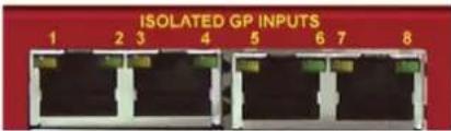
Fig 11-5: Isolated General Purpose Inputs
Inputs 1 – 8 are Opto-Isolated, Active High, Current Sink inputs. These ports read as active if input voltage exceeds approximately 1V.
Note: The maximum input range is 0 to +24VD.
Each RJ45 Socket handles two GPIs and provides access to a +5VD fused power supply as well as the Digital Ground for the unit.
-
GPI_1_IN
-
GPI 1 RETURN
-
GPI 2 IN
-
Not Connected
-
+5VD (Fused)
-
GPI 2 RETURN
-
Not Connected
-
DGND
Each of the first four top sockets follow this pattern from left to right.
Note: The TOTAL CURRENT that can be drawn from the +5VD fused supply is 200mA.
Active Low General Purpose Inputs
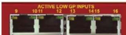
Fig 11-6: Active Low General Purpose Inputs
Inputs 9 – 16 are Active Low, pull to rail protected inputs. These ports read as active if the input voltage is below 1VD and are inactive at above 1.7VD, relative to the Digital ground of the unit.
Note: The maximum input range is -24VD to +24VD.
Each RJ45 handles two GPIs and provides access to Digital ground.
-
GPI_9
-
GPI 10
-
Not Connected
-
Not Connected
-
Not Connected
-
Not Connected
-
Not Connected
-
DGND
Each of the four top sockets follow this pattern from left to right.
Analogue Control Voltage Inputs

Fig 11-7: Analogue Control Voltage Inputs
Inputs 1 – 8 with 3 off hardware preset, voltage ranges.
Note: The maximum voltage input range is equal to the range for the pins being used.
Each RJ45 socket handles two Inputs, with three voltage ranges for each.
- Analogue Input 1, 0V - 12V Range
- Analogue Input 1, 0V - 5V Range
- Analogue Input 1, 0V - 3.3V Range
- Analogue Input 2, 0V - 12V Range
- Analogue Input 2, 0V - 5V Range
- Analogue Input 2, 0V - 3.3V Range
- Not Connected
- Analogue Ground
Each of the top four sockets follows this pattern from left to right.
RB-IPE Outputs
Relay General Purpose Outputs
Outputs 1 – 8 are Isolated Relay
Changeover Contacts.
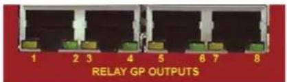
Fig 11-8: Relay General Purpose Outputs
Note: The nominal switching capacity (resistive load) is1A @ 30V DC (0.5A @125V AC).
Each RJ45 sockets handles two GPO Relays and provides 3 contacts for each.
- Output Relay 1, Contact: Common 1
- Output Relay 2, Contact: Common 2
- Output Relay 1, Contact: Normally Open 1
- Output Relay 1, Contact: Normally Closed 1
- Output Relay 2, Contact: Normally Closed 2
- Output Relay 2, Contact: Normally Open 2
- Not Connected
- Not Connected
Each of the first four bottom sockets follow this pattern from left to right.
Note: Outputs 1 – 8 are mechanical relays. As such they have relatively slow switching times and have a limited lifetime in terms of mechanical operations. Commanding these ports to switch at high speeds could prove unreliable and will wear the hardware out more quickly.
Opto-Isolated General Purpose Outputs

Fig 11-9: Opto-Isolated General Purpose Outputs
Outputs 9 – 16 are Opto-Isolated closing contacts.
Note: The maximum collector/emitter voltage peak is 35V DC @ 7mA. The maximum collector/emitter current is 80mA @ 2.5V DC.
Each RJ45 socket handles two GPO Opto-Isolators and provides access to a fused +5VD supply and the Digital Ground for the unit.
- GPO_9_COLLECTOR
- GPO_9_EMITTER
- GPO 10 COLLECTOR
- Not Connected
- +5VD (Fused)
- GPO_10_EMITTER
- Not Connected
- DGND
Each of the second four bottom sockets follow this pattern from left to right.
Note: In order to achieve the best response time ensure the output is loaded.
11 Talkback & Communications - RB- IPE
Analogue Control Voltage Outputs
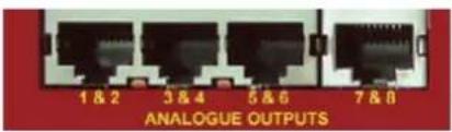
Fig 11-10: Analogue Control Voltage Inputs
Outputs 1 – 8 have 3 off software controlled voltage ranges.
Note: The maximum current per output is 5mA @ 12V / 30mA @ 5V / 25mA @ 3.3V.
Each RJ45 socket handles two outputs, with three voltage ranges for each.
- Analogue Output 1
- Analogue Output 2
- Not Connected
- Not Connected
- Not Connected
- Not Connected
- Not Connected
- Analogue Ground
Each of the four bottom sockets follow this pattern from left to right.
Ethernet Port
Standard CAT5 cable and configuration, 10Mbps or 100Mbps speed selectable.
Ethernet Interface Commands and Responses
Most of the commands follow the same structure: a 3 letter command followed by a colon, followed by one or more parameters delimited with a comma, and terminated by Carriage Return with optional Line Feed. A Line Feed character may be sent but it will be ignored by the RB-IPE. Commands are case sensitive.
Responses are CR & LF terminated and all commands may be issued by UDP or TCP/IP to port 31781 on the RB-IPE.
Following are the commands and the expected responses. Because there are quite a few commands, they are grouped into relevant subsections:
Identification and Network Commands:
Please Note: The unit defaults with DHCP enabled. If no DHCP server is found, after 45 seconds the unit applies the default static network settings:
IP Address = 192.168.0.100
Net Mask = 255.255.255.0
Gateway = 192.168.0.1
Otherwise, DHCP can be turned on / off using the NOP: command. The Static Network settings can be modified using the NET: command.
Communication Sequencing:
For tracking / debugging purposes the IPE will accept a 5 character identifier in front of any command it receives. This identifier must be in the form:
NNNN# - where N = any character, and # is the delimiter between the identifier and the command itself.
An example Command might be:
30CB#GPI:? - which could be the 12491st request for GPI Statuses or a single request from a source identified as "30CB".
The IPE will automatically copy this identifier (if in the correct format) to its
response message. In this way you can monitor the order and number of commands processed, as well as differentiating between responses to commands from different sources to the same IPE.
Command Description Parameters Response
| UID:? Identify Units on the Network ‘?’ Character UID:RB-IPE-01,SSSSSS,Example Name,Status | |||
| (Device Model, 6 Digit Serial Number, User Assigned Name, Pairing Status) | |||
| NET:ipaddr, netmask,gw | Set the Static Network settings for the unit | ipaddr = IP Address e.g. 192.168.0.100netmask = Network Mask e.g. 255.255.255.0gw = Gateway | ACK: |
| NET:x Return the current network configuration | x = 0 to return static addressx = 1 to return current address assigned by DHCP | NET:x,ipaddr,netmask,gwNET:1, 192.168.0.100, 255.255.255.0, 192.168.9.1 (for example) | |
| NOP:x{,y} Get or Set the Network options for DHCP | x = option (0 = DHCP option)y = 0 or 1 (0 = Disable, 1 = enable) | NOP:x,y (return current option settings)orACK: (acknowledge changes) | |
| SER:? Get the device Serial Number ‘?’ Character SER:SSSSSS | Six digit serial as a decimal string. | ||
| MAC:? Get the device Hardware or MAC address | ‘?’ Character MAC:nnnnnnnnnnnn | Hardware Address string in Hex format | |
| VER:? Get the current firmware version | ‘?’ Character VER:{BOOT}M.m.b | BOOT is only sent when device is in bootstrap modeM = Major version numberm = Minor version numberb = Build number | |
| WID:sssssss sssss | Set the User Configured Name for the unit | Name should be a string of up to 12 characters | ACK: |
11 Talkback & Communications - RB- IPE
Port Configuration Commands:
| Command Description Parameters Response | |||
| GPI:? Get Status of GPI ports ‘?’ Character GPI:x | |||
| e.g. GPI:0100000100100100116 bit number corresponding to 16 GPI ports:0 = Inactive1 = Active | |||
| GPI:x Set GPO ports according to response from paired unit | x = 16 bit number representing the status of the input ports on the paired unit | None | |
| GPO:p,x{,y} Set GPO port state, or set GPOPort Start-Up State | p = GPO port number 1 -16x = State: 1 Active, 0 Inactivey = 1 to set Power Up State | ACK: | |
| GPO:x Get the current GPO Port Statusof the unit | x = ‘?’ GPO:n where n = 16 bit number with each bit corresponding to the state of each GPO port | ||
| MAP:x,x,x,x,x,x,x,x,x,x,x,x,x,x,x,x,x,x,x,x,x,x,x,x,x,x,x,x,x,x,x,x,x,x,x,x,x,x,x,x,x,x,x,x,x,x,x,x,x,x,x,x,x,x,x,x,x,x,x,x,x,x,x,x,x,x,x,x,x,x,x,x,x,x,x,x,x,x,x,x,x,x,x,x,x,x,x,x,x,x,x,x,x,x,x,x,x,x,x,x,x,u,x,x,x,x,x,x,x,x,x,x,x,x,x,x,x,x,x,x,x,x,x,x,x,x,x,x,x,x,x,x,x,x,x,x,x,x,x,x,x,x,x,x,x,x,x,x,x,x,x,x,x,x,x,x,x,x,x,x,x,x,x,x,x,x,x,x,x,x,x,x,x,x,x,x,x,x,x,x,x,x,x,x,x,x,x,x,x,x,x,x,x,x,x,x,x,x,x,x,x;x,x,x,x,x,x,x,x,x,x,x,x,x,x,x,x,x,x,x,x,x,x,x,x,x,x,x,x,x,x,x,x,x,x,x,x,x,x,x,x,x,x,x,x,x,x,x,x,x,x,x,x,x,x,x,x,x,x,x,x,x,x,x,x,x,x,x,x,x,x,x,x,x,x,x,x,x,x,x,x,x,x,x,x,x,x,x,x,x,x,x,x,x,x,x,x,x,x,x,x,t,x,t,t,t,t,t,t,t,t,t,t,t,t,t,t,t,t,t,t,t,t,t,t,t,t,t,t,t,t,t,t,t,t,t,t,t,t,t,t,t,t,t,t,t,t,t,t,t,t,t,t,t,t,t,t,t,t,t,t,t,t,t,t,t,t,t,t,t,t,t,t,t,t,t,t,t,t,t,t,t,t,t,t,t,t,t,t,t,t,t,t,t,t,t,t,t,t,t,t,t,t:t,x,t,t,t,t,t,t,t,t,t,t,t,t,t,t,t,t,t,t,t,t,t,t,t,t,t,t,t,t,t,t,t,t,t,t,t,t,t,t,t,t,t,t,t,t,t,t,t,t,t,t,t,t,t,t,t,t,t,t,t,t,t,t,t,t,t,t,t,t,t,t,t,t,t,t,t,t,t,t,t,t,t,t,t,t,t,t,t,t,t,t,t,t,t,t,t,t,t,t, | Set the routing from remote GPI ports to the local GPO ports | x = GPI port number 0 – 15(corresponding to 1 – 16)Each x value from left to right corresponds to a GPO port on the local unit. Insert the number of the remote input port that you want to forward to each output. | ACK: |
| GLK:x,x,x,x,x,x,x,x,x,x,x,x,x,x,x,x,x,x,x,x,x,x,x,x,x,x,x,x,x,x,x,x,x,x,x,x,x,x,x,x,x,x,x,x,x,x,x,x,x,x,x,x,x,x,x,x,x,x,x,x,x,x,x,x,x,x,x,x,x,x,x,x,x,x,x,x,x,x,x,x,x,x,x,x,x,x,x,x,x,x,x,x,x,x,x,x,x,x,x,u,w,x,x,x,x,x,x,x,x,x,x,x,x,x,x,x,x,x,x,x,x,x,x,x,x,x,x,x,x,x,x,x,x,x,x,x,x,x,x,x,x,x,x,x,x,x,x,x,x,x,x,x,x,x,x,x,x,x,x,x,x,x,x,x,x,x,x,x,x,x,x,x,x,x,x,x,x,x,x,x,x,x,x,x,x,x,x,x,x,x,x,x,x,x,x,x,x,x,x,x,s,x,s,x,s,x,s,s,s,s,s,s,s,s,s,s,s,s,s,s,s,s,s,s,s,s,s,s,s,s,s,s,s,s,s,s,s,s,s,s,s,s,s,s,s,s,s,s,s,s,s,s,s,s,s,s,s,s,s,s,s,s,s,s,s,s,s,s,s,s,s,s,s,s,s,s,s,s,s,s,s,s,s,s,s,s,s,s,s,s,s,s,s,s,s,s,s,s,s,s,s,s,s,s,s,s,a,w,x,x,x,x,x,x,x,x,x,x,x,x,x,x,x,x,x,x,x,x,x,x,x,x,x,x,x,x,x,x,x,x,x,x,x,x,x,x,x,x,x,x,x,x,x,x,x,x,x,x,x,x,x,x,x,x,x,x,x,x,x,x,x,x,x,x,x,x,x,x,x,x,x,x,x,x,x,x,x,x,x,x,x,x,x,x,x,x,x,x,x,x,x,x,x,x,x,x,u,v,w,x,v,w,v,w,v,w,v,w,v,w,v,w,v,w,v,w,v,w,v,w,v,w,v,w,v,w,v,w,v,w,v,w,v,w,v,w,v,w,v,w,v,w,v,w,v,w,v,w,v,w,v,w,v,w,v,w,v,w,v,w,v,w,v,w,v,w,v,w,v,w,v,w,v,w,v,w,v,w,v,w,v,w,v,w,v,w,v,w,v,w,v,w,v,w,v,w,v,w,v,w,v w,v,w,v,w,v,w,v,w,v,w,v,w,v,w,v,w,v,w,v,w,v,w,v,w,v,w,v,w,v,w,v,w,v,w,v,w,v,w,v,w,v,w,v,w,v,w,v,w,v,w,v,w,v,w,v,w,v,w,v,w,v,w,v,w,v,w,v,w,v,w,v,w,v,w,v,w,v,w,v,w,v,w,v,w,v,w,v,w,v,w,v,w,v,w,v,w,v,w,vw,v,w,v,w,v,w,v,w,v,w,v,w,v,w,v,w,v,w,v,w,v,w,v,w,v,w,v,w,v,w,v,w,v,w,v,w,v,w,v,w,v,w,v,w,v,w,v,w,v,w,v,w,v,w,v,w,v,w,v,w,v,w,v,w,v,w,v,w,v,w,v,w,v,w,v,w,v,w,v,w,v,w,v,w,v,w,v,w,v,w,v,w,v,w,v,w,v,w,v-w,v,w,v-w,v,w-v,w-w,v-w,v-w,v-w,v-w,v-w,v-w,v-w,v-w,v-w,v-w,v-w,v-w,v-w,v-w,v-w,v-w,v-w,v-w,v-w,v-w,v-w,v-w,v-w,v-w,v-w,v-w,v-w,v-w,v-w,v-w,v-w,v-w,v-w,v-w,v-w,v-w,v-w,v-w,v-w,v-w,v-w,v-w,v-w,v-w,v-w,v-w,v-w,v-w,v-w,v-wv-v-w-w-w-w-w-w-w-w-w-w-w-w-w-w-w-w-w-w-w-w-w-w-w-w-w-w-w-w-w-w-w-w-w-w-w-w-w-w-w-w-w-w-w-w-w-w-w-w-w-w-w-w-w-w-w-w-w-w-w-w-w-w-w-w-w-w-w-w-w-w-w-w-w-w-w-w-w-w-w-w-w-w-w-w-w-w-w-w-w-w-w-w-w-w-w-w-w-w-w-w-v-w-w-w-w-w-w-w-w-w-w-w-w-w-w-w-w-w-w-w-w-w-w-w-w-w-w-w-w-w-w-w-w-w-w-w-w-w-w-w-w-w-w-w-w-w-w-w-w-w-w-w-w-w-w-w-w-w-w-w-w-w-w-w-w-w-w-w-w-w-w-w-w-w-w-w-w-w-w-w-w-w-w-w-w-w-w-w-w-w-w-w-w-w-w-w-w-w-w- | Set Permissions for GPO state changes | x = number from 0 – 100 = Locked to remote GPI via mapping1 – 8 = Locked to local Analogue Input 1 – 8, via Thresholds9 = locked high10 = locked low | ACK: |
| INV:x Set inversion state for the GPOports | x = 16 bit number where each bit corresponds to GPO ports 1 – 16x = 1 Output is inverted with respect to remote GPIx = 0 Output logic is Non-Inverted | ACK: | |
| ADC:? Get the analogue input values as a series of decimal numbers | '?' Character ADC:x,x,x,x,x,x,x,x,x | ||
| x = a 10 bit ADC read value corresponding to channels 1 to 8 from left to right | |||
| ADC:x,x,x,x,x,x,x,x,x | Set Analogue outputs according to response from a paired unit | x = a 10 bit ADC read value corresponding to channels 1 – 8 from left to right | None |
| DAC:p,x Set Analogue output level p = port number 1 – 8 | x = 10 bit number from 0 – 1023 (full scale) | ACK: | |
| DAC:x Get the current Analogue OutputPort Status of the unit | x = '?' DAC:n,n,n,n,n,n,n,n where n = 10 bit number corresponding to the level of each analogue output port | ||
| DAC:p,x,l,r,m Configure the Analogue Outputs p = Port Number 1 – 8 | x = 16 bit Start up Value 0 – 65535l = 16 bit Limit Valuer = Voltage Range (0 = 3V3, 1 = 5V, 2 = 12V)m = conversion (0 = linear, 1 = logarithmic) | ACK: | |
| MAP:x,x,x,x,x,x,x,x | Set the routing from remote Analogue inputs to local Outputs | x = Analogue port number 0 – 7 (corresponding to 1 – 8)Each x value from left to right corresponds to a local output port.Insert the number of the remote input port that you want to forward to each output. | ACK: |
11 Talkback & Communications - RB- IPE
| ALK:x,x,x,x,x,x,x,x,x | Set permissions for Analogue output state changes | x = 0 port locked to remote analogue input via mappingx = 1 port locked to a single preset levelx = 2 port Locked to zero output level | ACK: |
| THR:x,x,x,x,x,x,x,x,x | Set Threshold values for each analogue input | x = analogue input threshold level between 0 – 1023 corresponding to ports 1 – 8 from left to right | ACK: |
| ACT:x,x,x,x,x,x,x,x,x | Set the GPO state to be enforced when each input threshold is exceeded | x = 0 GPO inactive above threshold, active belowx = 1 GPO active above threshold, inactive below | ACK: |
| LVL:x,x,x,x,x,x,x | Preset the values to which each analogue output can be locked | x = 16 bit number between 0 – 65535 corresponding to Analogue voltage full-scale output range. | ACK: |
| UPD:x,yorUPD:x,y,ms,s,m,horUPD:x,y,ms,s,m,h,z | Set how the unit communicates the status of the input ports. (This command accepts 2, 6 or 7 parameters) | x: GP (0) or Analogue (1) Selection y: Update Setting:Passive(0) On Change(1) Periodic(2) Update period setting:ms: 0 – 999 Milliseconds: 0 – 59 Secondsm: 0 – 59 Minutesh: 0 – 24 Hoursz: Step change required at Analogue input before a Status Update occurs: 1 - 50 | ACK: |
Error Messages:
The following error messages can be returned for illegal commands:
ERR:02-Returned if command unknown
ERR:03-Returned if invalid number of parameters
ERR:04-Returned if any parameter is invalid
Talkback & Communications - RB- IPE 11
RB-IPE Webserver
The built in webserver on each RB-IPE allows you to control the unit remotely through a web browser. The webpage interface has multiple tabs including; Home, Network, Configuration and Update.
To access the webpage simply type the IP address of the unit you wish to connect with, into the address bar of your internet browser.
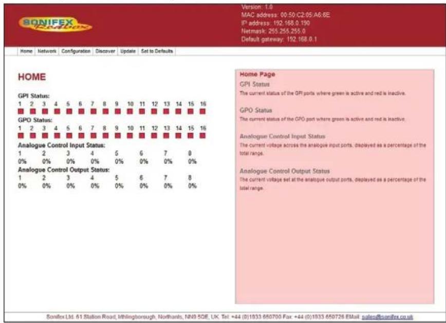
Fig 11-11: Screen shot of the RB-IPE Webserver home page
The top banner contains useful current information about the unit you are connected to, such as Version Number and Network Address settings. The Menu Bar just below this banner allows you to navigate through various
pages to configure different aspects of the unit. Each page follows the same standard layout as the home page, with current status / configuration settings on the left hand side and tooltip explanations in the red box to the right. The bottom banner contains contact details for Sonifex Ltd.
Home – Shows the current status of all input/output ports of the RB-IPE.
Network – For configuration of the static/dynamic network settings and naming of the unit.
Configuration – Separate pages for the configuration of General Purpose and Analogue I/O as well as Communication settings for the unit. There is also a page for the configuration of the IPE port and remote (inter-network) link settings.
Discover – Allows the unit to locate and pair with other RB-IPE units on the local network.
Update – Performs a firmware update.
Default – This resets all port configurations back to default settings.
Updating the RB-IPE
Firmware updates may be downloaded by visiting: https://www.sonifex.com/technical/software/
To check if your RB-IPE requires an update, compare the version number displayed on the webpage of the unit, with the latest firmware download for the RB-IPE on the Sonifex website.
11 Talkback & Communications - RB- IPE
- If your firmware is out of date, download the new file and save it to an appropriate location.
- Navigate to the update page of the unit you wish to update.
- Click 'Browse' then locate the files you have just downloaded and select the '.DWN' file.
- Once the correct file has been selected, hit 'Update'.
- Once the update process is complete you will need to restart the RB-IPE in order to run the new firmware.
Technical Specification For RB-IPE
Rear Panel Connections
Isolated GPI: 4 x RJ45 sockets, with LED status indicator per input
Active Low GPI: 4 x RJ45 sockets, with LED status indicator per input
Relay GPO: 4 x RJ45 sockets, with LED status indicator per output
Isolated GPO: 4 x RJ45 sockets, with LED status indicator per output
Analogue Control Inputs: 4 x RJ45 sockets
Analogue Control Outputs: 4 x RJ45 sockets
Ethernet Port: RJ45 with status LEDs
Mains Input: Filtered IEC, continuously rated 85-264VAC @ 47-63Hz, 10W max
Fuse Rating: Anti-surge fuse 1A 20 x 5mm
Input & Output Detail
General Purpose Inputs:
8 x isolated current sink inputs from Inputs: 3.3V to +24V (Max input range: 0V to +24V)
8 x pull to ground protected inputs (Max input range -24V to +24V)
General Purpose Outputs:
8 x isolated relay change-over contacts: Nominal switching capacity
(resistive load): 1A @ 30V DC (0.5A @ 125V AC) 8 x opto-isolated contacts: Maximum collector/emitter voltage peak: 35V DC @ 7mA Maximum collector/emitter current: 80mA @ 2.5V DC (Note: There is a 200 mA fused +5V power supply available on GPI ports 1 – 8 and GPO ports 9 – 16.)
Analogue Control Inputs: 8 x 0V-3.3V, 5V or 12V input signals
Analogue Control 8 x output signals, nominally 0V-3.3V, 5V Outputs: or 12V
Front Panel Indicators
Power On: Red LED
CONNECTED: Green link status LED
GPIO: Green GPIO change status LED
ANALOGUE: Green analogue control I/O change status LED
Equipment Type
RB-IPE:

IP extender for GPIO & analogue control signals
Physical Specification
Dimensions (Raw): 48cm (W) x 10.8cm (D) x 4.2cm (H) (1U) 19" (W) x 4.3" (D) x 1.7" (H) (1U) Dimensions
(Boxed): 58.5cm (W) x 22.5cm (D) x 7cm (H) 23" (W) x 8.9" (D) x 2.75" (H)
Weight: Nett: 1.6kg Gross: 2.2kg Nett: 3.5lbs Gross: 4.8lbs
Accessories
RB-RK3
1U Rear panel rack kit for large Redboxes
12 RB-TGHD(B&X) Multi-Channel High Definition Tone Generator
Introduction


DIPSwitch Settings Channel Active LEDs
Fig 12-1: RB-TGHDX Front Panel
The RB-TGHD is a 1U rack-mount, 8 channel audio tone generator that provides line identification for multi-channel audio systems, including 5.1 and 7.1 surround sound typically used in high definition television broadcasts. By using a range of widely accepted industry standard tone sequences, channel identification and associated levels can be determined easily. Correct channel configuration in fold-down mixes can also be highlighted when a broadcaster needs to mix several audio channels into a stereo feed.
The RB-TGHD caters for 2, 4, 6 and 8 channel configurations and all of the available audio tone sequences for each channel configuration can be cycled through automatically, or selected manually, and a loop mode allows patterns of tones to be repeated. A bank of 4 pushbuttons on the front panel sets these options and the associated LEDs indicate the current setting. A set of 8 LEDs on the front panel indicate which channel is currently outputting audio.
The audio line-up level can be adjusted from 0dBu to +24dBu in 1dBu steps and the digital sample rate can be set from 32 kHz to 192 kHz in both 16
bit and 24 bit formats. As standard, the RB-TGHD has TTL wordclock input synchronisation. This can optionally be upgraded to a digital audio input or an analogue or digital video input.
The RB-TGHD is available in two variations. Both models provide 8 channels of audio in both analogue and digital formats. The balanced analogue outputs are via 3 pin XLR connectors. The RB-TGHDX has balanced AES/EBU digital outputs via 3 pin XLR connectors. The RB-TGHDB has unbalanced digital outputs via BNC connectors. When using the internally generated master clock, Channel Status information is generated and encoded on the digital output channels with the appropriate bits for sample rate and sample width set accordingly.
The serial port allows the RB-TGHD to be connected to a PC running SCI - the Sonifex Software Control Interface. This allows full control of the unit and the ability to generate a user defined audio tone sequence of up to 60 seconds in duration. In addition, a remote port on the rear provides a simple interface to control the unit and several outputs to indicate which tone sequence is active.
12 Talkback & Communications - RB-TGHDB & RB-TGHDX
Front Panel Controls & Indicators
All of the RB-TGHD's user controls and configuration settings are located on the front panel. Each push button has a range of LEDs associated with it that illuminate to show the current selection.
The LED on the left of the front panel is normally red to indicate that power is present on the unit.
Channel Active LEDs
These 8 LEDs provide a visual indication of which channels are currently outputting audio tones.
Channels Button & LEDs
This button selects the number of channels that output audio, from 2, 4, 6 or 8. If a sequence is active when this setting is changed, and the sequence is valid for the new channel setting, the sequence will automatically restart. Otherwise, the sequence will stop. The channel button illuminates red when it is pressed. The default setting is 8 channels.
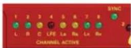
Fig 12-2: Channel Active LEDs
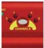
Fig 12-3: Channels Button & LEDs
Sequence Mode Button & LEDs
This button selects either auto or manual sequence mode. Auto mode cycles through all sequences that are enabled by the current channel setting (see Table 1-1). Manual mode allows individual sequences that are enabled by the current channel setting to be selected. The sequence mode button illuminates red when it is pressed. The default setting is auto mode.
Sequence Button & LEDs
This button selects the current sequence when the sequence mode is set to manual. In auto sequence mode, all the available sequences are cycled through and this button is disabled with the LEDs indicating which sequence is currently active. Table 1-1 shows which sequences are available for each channel setting. The sequence button illuminates red when it is pressed. The default setting is a combination of BLITS Channel Identification on channels 1-6 and EBU R49 Stereo Line-up on channels 7-8. The user sequence can only be selected if a valid sequence has been entered using the SCi software. Once entered, the user sequence is stored in internal non-volatile memory and will not be lost when power to the unit is removed.
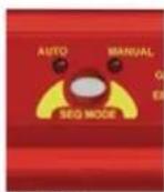
Fig 12-4: Sequence Mode Button & LEDs
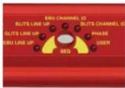
Fig 12-5: Sequence Button & LEDs
Talkback & Communications - RB-TGHDB & RB-TGHDX
| 2Channels | 4Channels | 6Channels | 8Channels | ||||
| EBU R49 Stereo Line-up | √ | √ | √ | √* | |||
| GLITS Stereo Line-up | √ | √ | √ | √* | |||
| BLITS Stereo Line-up | √ | √ | √ | √* | |||
| EBU R49 Channel Identification | × | × | √ | √ | |||
| BLITS Channel Identification | × | √ | √ | √ | |||
| Phase | √ | √ | √ | √ | |||
| User | √ | √ | √ | √ | |||
* Stereo Line-up sequence also available on channels 7-8 in combination with BLITS Channel Identification
Table 12-1: Valid Sequences For Channel Configurations
Sequence Loop Button & LEDs
This button enables the sequence loop mode which will continuously loop the selected sequence in manual sequence mode, or cycle through each available sequence in auto sequence mode. Sequence loop mode is enabled or disabled by pressing and holding the button for 1 second. This button has a second function; a momentary press resets the current active sequence. The effect of this depends on the current sequence mode and sequence loop settings as shown below in Table 1-2.

Fig 12-6: Sequence Loop Button & LEDs
| Sequence Mode: Auto | Sequence Mode: Manual | |
| Sequence Loop: Enabled | Restarts current active sequence | Restart current selected sequence |
| Sequence Loop: Disabled | Restarts the first available sequence |
Table 12-2: Sequence Restart Button Action
The sequence loop button illuminates red when it is pressed, and it flashes green when a sequence is active. The default setting is sequence loop enabled.
DIPSwitch Settings
There are a total of 16 DIPSwitches arranged in 2 banks of 8, located behind a removable panel next to the channel active LEDs.

Fig 12-7: DIPSwitch Settings
Sample Rate - Bank 1 DIPSwitches 1-3
These switches set the sample rate for the digital outputs when the sync mode is set to internally generated master clock, as follows:
| Digital Sample Rate | Bank1 DIP Sw 1 | Bank 1 DIP Sw 2 | Bank 1 DIP Sw 3 |
| 32kHz Off Off Off | |||
| 44.1kHz On Off Off | |||
| 48kHz Off On Off | |||
| 88.2kHz On On Off | |||
| 96kHz Off Off On | |||
| 176.4kHz On Off On | |||
| 196kHz Off On On | |||
| Not used On On On |
Table 12-3: Digital Sample Rate Settings
12 Talkback & Communications - RB-TGHDB & RB-TGHDX
Sync Mode - Bank 1 DIPSwitches 4-5
These switches configure the RB-TGHD to synchronize the digital audio outputs to either an internally generated master clock, or an external source via an add-on external sync board. The wordclock sync boards is fitted as standard. A range of other sync boards are available allowing synchronization to external analogue and digital video signals, as well as digital audio clocks. Once installed, the RB-TGHD will automatically detect the type of external sync board fitted. The DIP switch settings are as follows:
| Synchronization Mode | Bank 1 DIP Sw 4 | Bank 1 DIP Sw 5 |
| Internally generated master clock Off Off | ||
| External synchronization (when using sync board) | On Off | |
| Not used Off On | ||
| Not used On On |
Table 12-4: Synchronization Mode Settings
When using an external sync board, the sync LED will illuminate green when the RB-TGHD has successfully locked. When not locked, this LED will illuminate red.
Sample Width - Bank 1 DIPSwitch 6
This switch configures the sample width for the digital outputs as follows:
| Digital Sample Width Bank 1 DIP Sw 6 | |
| 16 bit Off | |
| 24 bit On | |
Table 12-5: Digital Sample Width Settings
Audio Line-Up - Bank 2 DIPSwitches 1-5
These switches set the audio line-up level for full scale digits. This setting allows 0dBFS to be set from 0dBu to +24dBu as shown in the following table:
| Audio Line-up DIP | Sw 1 DIP Sw | Sw 2 DIP Sw | 3 DIP Sw 4 | DIP Sw 5 | |
| 0dBFS = 0dBu Off | Off Off Off Off | ||||
| 0dBFS = +1dBu On | Off Off Off Off | ||||
| 0dBFS = +2dBu Off | On Off Off Off | ||||
| 0dBFS = +3dBu On | On Off Off Off | ||||
| 0dBFS = +4dBu Off | Off On Off Off | ||||
| 0dBFS = +5dBu On | Off On Off Off | ||||
| 0dBFS = +6dBu Off | On On Off Off | ||||
| 0dBFS = +7dBu On | On On Off Off | ||||
| 0dBFS = +8dBu Off | Off Off On Off | ||||
| 0dBFS = +9dBu On | Off Off On Off | ||||
| 0dBFS = +10dBu | Off | On | Off | On | Off |
| 0dBFS = +11dBu | On | On | Off | On | Off |
| 0dBFS = +12dBu | Off | Off | On | On | Off |
| 0dBFS = +13dBu | On | Off | On | On | Off |
| 0dBFS = +14dBu | Off | On | On | On | Off |
| 0dBFS = +15dBu | On On | On On Off | |||
| 0dBFS = +16dBu | Off Off | Off Off On | |||
| 0dBFS = +17dBu | On Off | Off Off On | |||
| 0dBFS = +18dBu | Off | On | Off | Off | On |
| 0dBFS = +19dBu | On On | Off Off On | |||
| 0dBFS = +20dBu | Off | Off | On | Off | On |
| 0dBFS = +21dBu | On | Off | On | Off | On |
| 0dBFS = +22dBu | Off | On | On | Off | On |
| 0dBFS = +23dBu | On | On | On | Off | On |
| 0dBFS = +24dBu | Off Off | Off On On | |||
Table 12-6: Audio Line-Up Settings
Talkback & Communications - RB-TGHDB & RB-TGHDX 12
Force Bootloader Mode - Bank 2 DIP Switch 8
This mode should only be used if the unit fails to respond after a firmware upgrade attempt. With this DIP switch On, and all others in Bank 2 set to Off, the RB-TGHD will force the Bootloader to run and allow initiation of an update under any circumstances. Once an update has completed, this switch should be returned to the Off position.
Reset Button
In the unlikely event that the RB-TGHD unit fails to respond, press the recessed reset button via the small hole in the front panel.
Sequence Details
There are 6 pre-defined sequences on the RB-TGHD. Each channel that is used in a sequence is assigned a tone frequency and an audio level. These values remain constant while the sequence is active. When a channel is un-muted, the corresponding LED on the front panel is illuminated. All channels are muted at the start of a sequence. An additional 'user' sequence can be programmed into the unit via the SCi software.
EBU R49 Stereo Line-Up Sequence
Number of channels: 2
Channel 1 configuration: 1kHz at 0dBu
Channel 2 configuration: 1kHz at 0dBu
Total duration: 6.5 seconds
| Offset from start of sequence in ms Action | |
| 0 Un-mute channels 1 & 2 | |
| 3000 Mute channel 1 | |
| 3250 Un-mute channel 1 | |
| 6250 Mute channel 1 | |
| 6500 | Mute all channels – End of sequence |
GLITS Stereo Line-Up Sequence
Number of channels: 2
Channel 1 configuration: 1kHz at 0dBu
Channel 2 configuration: 1kHz at 0dBu
Total duration: 4.0 seconds
| Offset from start of sequence in ms Action | |
| 0 Un-mute channel 2 | |
| 375 Un-mute channel 1 | |
| 750 Mute channel 2 | |
| 1125 Un-mute channel 2 | |
| 1500 Mute channel 2 | |
| 1875 Un-mute channel 2 | |
| 4000 | Mute all channels – End of sequence |
BLITS Stereo Line-Up Sequence
Number of channels: 2
Channel 1 configuration: 1kHz at 0dBu
Channel 2 configuration: 1kHz at 0dBu
Total duration: 5.3 seconds
12 Talkback & Communications - RB-TGHDB & RB-TGHDX
| Offset from start of sequence in ms Action | |
| 0 Un-mute channels 1 & 2 | |
| 1000 Mute channel 1 | |
| 1300 Un-mute channel 1 | |
| 1600 Mute channel 1 | |
| 1900 Un-mute channel 1 | |
| 2200 Mute channel 1 | |
| 2500 Un-mute channel 1 | |
| 2800 Mute channel 1 | |
| 3100 Un-mute channel 1 | |
| 5300 | Mute all channels – End of sequence |
EBU R49 Channel Identification Sequence
Number of channels: 6 or 8
Channel 1 configuration: 1 kHz at 0dBu
Channel 2 configuration: 1 kHz at 0dBu
Channel 3 configuration: 1 kHz at 0dBu
Channel 4 configuration: 80Hz at +10dBu (limited to 0dBFS if 0dBFS is less than +10dBu)
Channel 5 configuration: 1 kHz at 0dBu
Channel 6 configuration: 1 kHz at OdBu
Channel 7 configuration: 1 kHz at 0dBu (omitted for 6 channel
configuration)
Channel 8 configuration: 1 kHz at 0dBu (omitted for 6 channel configuration)
Total duration: 12.0 seconds (6 channels), 14.0 seconds (8 channels)
| Offset from start of sequence in ms Action – 6 Channels | |
| 0 Un-mute all channels | |
| 3000 Mute channels 1-3 & 5-6 | |
| 3500 Un-mute channel 1 | |
| 4000 Mute channel 1 | |
| 4500 Un-mute channel 2 | |
| 5000 Mute channel 2 | |
| 5500 Un-mute channel 3 | |
| 6000 Mute channel 3 | |
| 6500 Un-mute channel 5 | |
| 7000 Mute channel 5 | |
| 7500 Un-mute channel 6 | |
| 8000 Mute channel 6 | |
| 9000 | Un-mute channels 1-3 & 5-6 |
| 12000 | Mute all channels – End of sequence |
Talkback & Communications - RB-TGHDB & RB-TGHDX
| Offset from start of sequence in ms Action – 8 Channels | |
| 0 Un-mute all channels | |
| 3000 Mute channels 1-3 & 5-8 | |
| 3500 Un-mute channel 1 | |
| 4000 Mute channel 1 | |
| 4500 Un-mute channel 2 | |
| 5000 Mute channel 2 | |
| 5500 Un-mute channel 3 | |
| 6000 Mute channel 3 | |
| 6500 Un-mute channel 5 | |
| 7000 Mute channel 5 | |
| 7500 Un-mute channel 6 | |
| 8000 Mute channel 6 | |
| 8500 Un-mute channel 7 | |
| 9000 Mute channel 7 | |
| 9500 Un-mute channel 8 | |
| 10000 Mute channel 8 | |
| 11000 | Un-mute channels 1-3 & 5-8 |
| 14000 | Mute all channels – End of sequence |
BLITS Channel Identification Sequence
Number of channels: 4, 6 or 8
Channel 1 configuration: 880Hz at 0dBu
Channel 2 configuration: 880Hz at 0dBu
Channel 3 configuration: 1318.5Hz at 0dBu
Channel 4 configuration: 82.4Hz at 0dBu
Channel 5 configuration: 659.2Hz at 0dBu (omitted for 4 channel configuration)
Channel 6 configuration: 659.2Hz at 0dBu (omitted for 4 channel configuration)
Channel 7 configuration: 329.6Hz at 0dBu (omitted for 4 & 6 channel configurations)
Channel 8 configuration: 329.6Hz at 0dBu (omitted for 4 & 6 channel configurations)
Total duration: 3.15 seconds (4 channels), 4.75 seconds (6 channels), 6.35 seconds (8 channels)
| Offset from start of sequence in ms Action – 4 Channels | |
| 0 Un-mute channel 1 | |
| 750 Mute channel 1 | |
| 800 Un-mute channel 2 | |
| 1550 Mute channel 2 | |
| 1600 Un-mute channel 3 | |
| 2350 Mute channel 3 | |
| 2400 Un-mute channel 4 | |
| 3150 | Mute all channels – End of sequence |
12 Talkback & Communications - RB-TGHDB & RB-TGHDX
| Offset from start of sequence in ms Action – 6 Channels | |
| 0 Un-mute channel 1 | |
| 750 Mute channel 1 | |
| 800 Un-mute channel 2 | |
| 1550 Mute channel 2 | |
| 1600 Un-mute channel 3 | |
| 2350 Mute channel 3 | |
| 2400 Un-mute channel 4 | |
| 3150 Mute channel 4 | |
| 3200 Un-mute channel 5 | |
| 3950 Mute channel 5 | |
| 4000 Un-mute channel 6 | |
| 4750 | Mute all channels – End of sequence |
| Offset from start of sequence in ms Action – 8 Channels | |
| 0 Un-mute channel 1 | |
| 750 Mute channel 1 | |
| 800 Un-mute channel 2 | |
| 1550 Mute channel 2 | |
| 1600 Un-mute channel 3 | |
| 2350 Mute channel 3 | |
| 2400 Un-mute channel 4 | |
| 3150 Mute channel 4 | |
| 3200 Un-mute channel 5 | |
| 3950 Mute channel 5 | |
| 4000 Un-mute channel 6 | |
| 4750 Mute channel 6 | |
| 4800 Un-mute channel 7 | |
| 5550 Mute channel 7 | |
| 5600 Un-mute channel 8 | |
| 6350 | Mute all channels – End of sequence |
Phase Sequence
Number of channels: 2, 4, 6 or 8
Channel configuration for all channels: 2kHz at -6dBu
Total duration: 3.3 seconds
| Offset from start of sequence in ms | Action – All Channels Configurations |
| 0 Un-mute all active channels | |
| 3300 | Mute all channels – End of sequence |
User Sequence
Number of channels: 2, 4, 6 or 8
Channel configuration for all channels: 20Hz to 16kHz at -48dBu to +24dBu
Total duration: 60 seconds maximum
Sequence can be programmed via the SCi software.
Talkback & Communications - RB-TGHDB & RB-TGHDX 12

Fig 12-8: RB-TGHDX Rear Panel
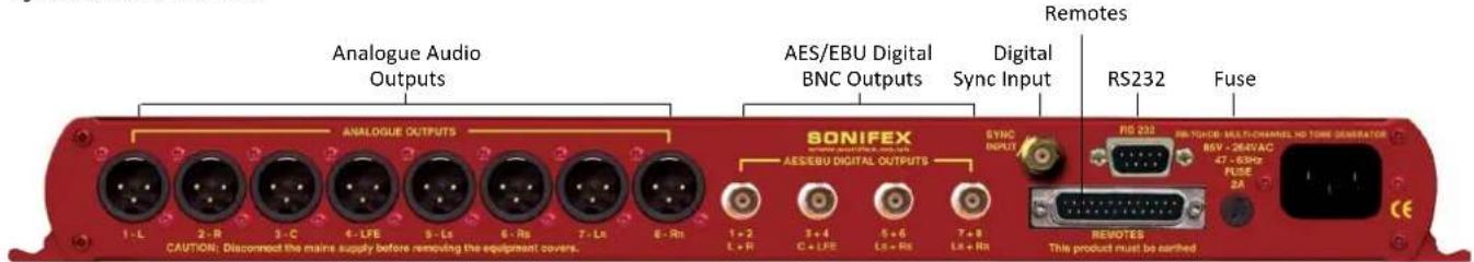
Fig 12-9: RB-TGHDB Rear Panel
Mains Power
Power is applied via a standard three-pin IEC male socket. Mains voltages between 85V and 264V AC and frequencies between 47 and 63Hz are accepted without adjustment. A 2A, 5 x 20mm SB fuse is used. The Earth pin MUST be connected to ensure safety.
Analogue Audio Outputs
The XLR 3 pin analogue audio output plug connectors are electronically balanced with an output impedance of less than 50Ω. They have the following connections:
Pin 1: Screen
Pin 2: Phase
Pin 3: Non-phase
Digital Audio Outputs - RB-TGHDX Model
The XLR 3 pin digital audio output plug connectors have an impedance of 110Ω. They have the following connections:
Pin 1: Screen
Pin 2: Phase
Pin 3: Non-phase
The signals on this connector will comply with the IEC 60968 specification.
Digital Audio Outputs - RB-TGHDB Model
The BNC socket digital audio output connectors have an impedance of 75Ω.
Word Clock Input
The BNC TTL word clock input has an impedance of 50Ω.
12 Talkback & Communications - RB-TGHDB & RB-TGHDX
RS232
The 9-way 'D' type socket connector carries a standard RS232 interface and allows direct connection to a serial port on a PC via a pin-to-pin cable. The pin assignments are as follows:
Pin 2: Transmit data
Pin 3: Receive data
Pin 5: Ground
All other pins are unused.
Remote Port
The 25-way 'D' type socket connector provides 17 active low inputs and 7 open collector driven outputs. The remote inputs are activated by shorting the relevant pin to Digital Ground (0V) on pin 1 and the functionality is shown in Table 1-7 below:
| Pin No. Function |
| 1 Digital Ground (0V) |
| 2 Select 2 Channels |
| 3 Select 4 Channels |
| 4 Select 6 Channels |
| 5 Select 8 Channels |
| 6 Select Auto Sequence Mode |
| 7 Select Manual Sequence Mode |
| 8 Select Sequence Loop On |
| 9 Select Sequence Loop Off / Restart Current Sequence |
| 10 Select EBU R49 Stereo Line-up Sequence |
| 11 Select GLITS Stereo Line-up Sequence |
| 12 Select BLITS Stereo Line-up Sequence |
| 13 Select EBU R49 Channel ID Sequence |
| 14 Select BL | TS Channel ID Sequence |
| 15 Select Phase Sequence | |
| 16 Select User Sequence | |
| 17 Mute Channels 1 & 2 whilst remote input active | |
| 18 Mute All Channels whilst remote input active | |
Table 12-7: Remote Inputs
The remote outputs show which sequence is currently active as show in table 8 below:
| Pin No. Function | |
| 19 Activated | when EBU R49 Stereo Line-up sequence is active |
| 20 Activated | when GLITS Stereo Line-up sequence is active |
| 21 Activated | when BLITS Stereo Line-up sequence is active |
| 22 Activated | when EBU R49 Channel ID sequence is active |
| 23 Activated | when BLITS Channel ID sequence is active |
| 24 Activated | when Phase sequence is active |
| 25 Activated | when User sequence is active |
Table 12-8: Remote Outputs
Talkback & Communications - RB-TGHDB & RB-TGHDX 12
Serial Interface Commands & Responses Protocol
Sonifex SCi remote control software handles all communication with the RB-TGHD via a convenient graphical user interface. However, this protocol is provided for those users who wish to develop their own remote control applications.
For more information on how to install and operate the SCi software, please see page 97.
Serial Data Format
Most of the commands follow the same structure: a 3 letter command followed by a colon, followed by a parameter (if any) and terminated by Carriage Return with optional Line Feed. A Line Feed character may be sent but it will be ignored by the RB-TGHD. Commands are not case sensitive. Responses will be CR & LF terminated.
After the Tone Generator has been powered-up, an initialisation string is sent "Sonifex
RB-TGHD" followed by the version number of the currently installed firmware.
Following are the commands and the expected responses:
| Command | Description | Response |
| Bnn: **Set Baud Rate where: ACK: (at old rate) | ||
| nn = 11 (115200 baud) | ||
| nn = 57 (57600 baud) | ||
| nn = 38 (38400 baud) | ||
| nn = 19 (19200 baud) | ||
| nn = 96 (9600 baud) | ||
| BSV: **Bootloader version request where: BOOT:Vn.n | ||
| n.n = bootloader version | ||
| DWN: **Download firmware ACK:New firmware installed when correct (ACK: indicates end of firmware file is received download can start) | ||
SCH:n Set number of channels where: ACK: or ERR:
n = 0 (2 channels)
n = 1 (4 channels)
n = 2 (6 channels)
n = 3 (8 channels)
SER: **Serial number request where: SER:z z = serial number (6 digits)
SRQ: **Status request where: STA:p_q_r_s_t_u_v_w_x_y_z
p = channel setting (bootloader returns STA: only)
q = sequence mode setting
r = sequence setting
s = sequence loop setting
t = sample rate setting
u = sample width setting
v = audio line-up setting
w = sync mode setting
x = sync board fitted
y = channels currently active
z = sync status
SRS: Sequence restart ACK:
SSL:n Set sequence loop where: ACK: or ERR:
n = 0 (sequence loop off)
n = 1 (sequence loop on)
SSM:n Set sequence mode where: ACK: or ERR:
n = 0 (auto sequence mode)
n = 1 (manual sequence mode)
SSQ:n Set sequence where: ACK: or ERR:
n = 0 (EBU R49 stereo line-up)
n = 1 (GLITS stereo line-up)
n = 2 (BLITS stereo line-up)
n = 3 (EBU R49 channel identification)
n = 4 (BLITS channel identification)
n = 5 (phase)
n = 6 (user)
n = 7 (BLITS channel identification + EBU stereo line-up)
n = 8 (BLITS channel identification + GLITS stereo line-up)
n = 9 (BLITS channel identification + BLITS stereo line-up)
n = A (load next valid sequence)
12 Talkback & Communications - RB-TGHDB & RB-TGHDX
UID: **Unit id request UID:RB-TGHD
VER: **Version number request where: VER:Vn.nnn
n.nnn = firmware version (bootloader returns BOOT:Vn.n)
n.n = bootloader version
USQ:0 User sequence control - loads current ACK: user sequence into RAM ready for editing
USQ:1 User sequence control - reads user USD:d
sequence from RAM where: followed by
d = total duration in ms USC:c,f,a,n
c = channel (0-7) for each channel, and
f = frequency in hz USS:c,s,o,t
a = amplitude in dBFS for each step on each channel
n = number of steps defined ACK: indicates read complete
s = step
o = offset in ms
t = action type (0=mute, 1=unmute)
USQ:2 User sequence control - saves user ACK: sequence after editing
USQ:3 User sequence control - deletes user sequence from memory ACK: or ERR:
USQ:4,d User sequence control - sets the total ACK: or ERR:
sequence duration where:
d = duration in milliseconds (max 60000)
USQ:5,c,f User sequence control - sets the tone ACK: or ERR:
frequency on a channel where:
c = channel (0-7)
f = frequency in hertz (min 20, max 16000)
USQ:6,c,a User sequence control - sets the tone ACK: or ERR:
amplitude on a channel where:
c = channel (0-7)
a = amplitude in dBFS
(min: 0=-48dBFS, max: 48=0dBFS)
USQ:7,c,o User sequence control - adds an ACK: or ERR:
unmute step on a channel where:
c = channel (0-7)
o = offset in milliseconds (min 0, max 59950)
USQ:8,c,o User sequence control - adds a mute ACK: or ERR:
step on a channel where:
c = channel (0-7)
o = offset in milliseconds (min 0, max 59950)
USQ:9,c,s User sequence control - deletes a ACK: or ERR:
step on a channel where:
c = channel (0-7)
s = step
USQ:A,c User sequence control - clears all ACK: or ERR:
settings on a channel where:
c = channel (0-7)
USQ:B,c,d User sequence control - copies all ACK: or ERR:
settings from one channel to
another where:
c = channel (0-7)
d = destination channel (0-7)

** = these commands also supported in Bootloader mode.
Error Messages
General error messages: ERR:01 = Returned if command not found ERR:02 = Returned if invalid command or missing/invalid parameter ERR:04 = Returned if parameter out of range User sequence programming error messages: ERR:10 = Returned if duration is out of range ERR:11 = Returned if frequency is out of range ERR:12 = Returned if amplitude is out of range ERR:13 = Returned if max number of steps are already defined ERR:14 = Returned if offset is out of range ERR:15 = Returned if step is out of range ERR:16 = Returned if channel is invalid ERR:17 = Returned if command not allowed due to user sequence being active
RB-TGHD SCI Remote Control Software
Sonifex SCi software is free of charge software available to control the RB-TGHD Tone Generators, as well as other Sonifex products, using RS232 connections.
Download the Latest SCi Software
This is located on the Sonifex website in the Software Downloads section: https://www.sonifex.co.uk/technical/software/index.shtml
Download and install the software.
Connecting the RS232 Serial Port
Simply connect your RB-TGHD to your computer using a serial cable and you are ready for operation.
Using SCI for the First Time
Once you have connected the serial cable, double click the SCi icon. You will be presented with the SCi Launcher:
Click on the large 'Plus' button and the software will try and communicate with the relevant serial ports to 'discover' your connected devices.

Fig 12-10: SCi Launcher

Fig 12-11: SCi Device Discovery Panel
Your attached RB-TGHD Tone Generator(s) will be shown in the list. If they are not listed, check the cable(s) between the RB-TGHD and your PC. Close the device dialog by clicking on the cross in the top right corner. The Tone Generator now appears in the SCI Launcher.
Loaded Launcher
Double-click on this to gain access to the Tone Generator controls.
SCI for RB-TGHD Tone Generators
The graphical interface allows you to control the RB-TGHD Tone Generator remotely. The controls replicate those on the front panel of the RB-TGHD - channel, sequence mode, sequence and sequence loop settings, as well the sequence restart
![Launcher sei Tone Generator RB-TGHD [000000]](/content/2026/06/1225749/images/19d627704b942b6fd082fdf43a3ed8307a87afdea617102be5c54c16cab9854c.jpg)
Fig 12-12: SCi Launcher Loaded
12 Talkback & Communications - RB-TGHDB & RB-TGHDX
control can all be accessed from this main panel. The channel active LEDs across the top of the screen show the state of each channel. This screen also shows additional information on the current DIPSwitch settings and details of the type of external sync board that is fitted, if any. Please note that SCi is continuously updated so the images may appear differently to those shown.
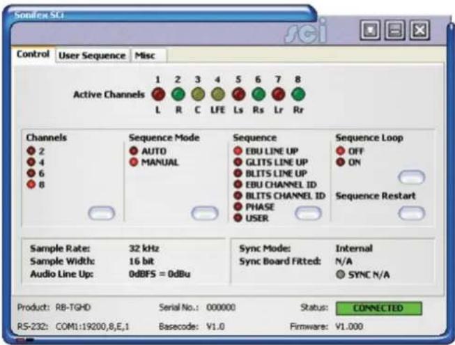
Fig 12-13: SCi Main Control Screen
To change a setting or start the currently selected sequence, simply press the associated button.
User Sequence Programming
This screen allows the user sequence to be easily edited. The sequence consists of up to 8 independently configured channels with a maximum of 50 steps on each channel. The bottom of the screen shows a graphical representation of the current sequence with the coloured regions showing when the channel will be un-muted.
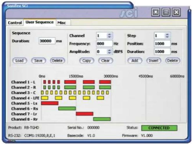
Fig 12-14: SCi User Sequence Screen
The Sequence Load button reads the current user sequence that is currently stored in the RB-TGHD memory and displays the details, overwriting any user sequence that is currently being edited. When the user sequence screen is selected, the current user sequence is automatically loaded.
The Sequence Save button performs a check on the user sequence data before writing the details to the RB-TGHD. Once a valid sequence has been written, it will be available for selection until it is overwritten or deleted.
Talkback & Communications - RB-TGHDB & RB-TGHDX
The Sequence Delete button clears the user sequence currently stored in the RB-TGHD.
The Sequence Duration edit sets the total running time for the sequence in milliseconds. The maximum duration is 60000 ms (60 seconds).
The Channel selector selects a channel to edit. As the channel is changed, the relevant data will be displayed.
The Channel Frequency edit sets the tone frequency for the selected channel. The Frequency value must be between 20Hz and 16000Hz.
The Channel Amplitude selector sets the audio amplitude for the selected channel between 0 dBFS and -48 dBFS.
The Channel Copy button allows the settings on one channel to be reproduced on a different channel. First select the channel to copy using the Channel selector, then press the Copy button. Now select a channel to copy to by clicking on one of the channel names in the lower half of the screen.
The Channel clear button deletes all the settings for the selected channel.
The Step selector selects a sequence step to edit. Each step is a period where the channel is un-muted.
The Step Position edit sets the point at which the channel un-mutes for the selected step. This value is an offset from the start of the sequence and is measured in milliseconds. The Position value must be between 0 ms and 59950 ms.
The Step Duration edit sets the length of the un-mute period for the selected step in milliseconds.
The Step Add button adds a new step to the selected channel. A maximum of 50 steps can be assigned to each channel.
The Step Insert button inserts a new step at the currently selected step. For
example, if there are 5 steps and the step selector is set to 3, a new step will be inserted at position 3 and the current steps at position 3, 4 and 5 will be moved to 4, 5 and 6 respectively.
The Step Delete button removes the currently selected step.
Firmware Updates
The Misc screen shows the Update Firmware option.
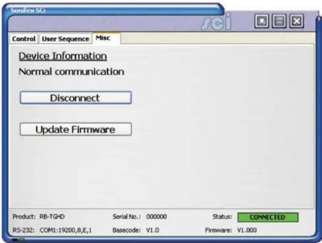
Fig 12-15: SCi Misc Screen
Occasionally, it may be necessary to upgrade the firmware on the RB-TGHD to add new functionality and fix software bugs. New firmware updates will be made available from time to time on the Sonifex website. Visit www.sonifex.co.uk for details.
It is vital that neither the serial connection nor mains power to the RB-TGHD should be interrupted during the update process. If this should
12 Talkback & Communications - RB-TGHDB & RB-TGHDX
happen, or the update is unsuccessful for any other reason, the RB-TGHD will not operate normally and will instead enter a protected Bootloader mode. In this mode, the unit has a limited command set and will await a successful retry of the update process.
Should the firmware update appear to succeed but the unit not behave as expected, the update may be repeated either via the DWN: command (if the unit will respond to commands) or, in extreme circumstances, by setting DIP switch number 8 in Bank 2 to ON. All other DIPSwitches in Bank 2 must be off. This action will force the Bootloader to run and allow initiation of an update under any circumstances. After completion of the update, the switch should be returned to the OFF position.
To upgrade the firmware on the connected RB-TGHD, click on the Update Firmware button and select the required firmware file. Once the firmware upgrade has started, all of the LEDs on the front panel of the RB-TGHD will turn off except for the sync LED which indicates the status of the upgrade process as shown:
| Sync LED State Status Of Firmware Upgrade |
| Flashing Amber Receiving firmware file |
| Constant Amber Programming new firmware |
| Constant Green New firmware installation successful |
| Constant Red New firmware installation failed – try again |
Table 12-9: Firmware Upgrade Status LED
The new firmware is transferred, and then the current firmware is erased before programming the update. Please note: Firmware files can take several minutes to transfer to the RB-TGHD at lower baud rates. To speed up the process, select a higher baud rate prior to transferring the new firmware.
Installing the Optional Sync Boards
There are 4 sync boards which can be used to synchronise the outputs of the RB-TGHD. The RB-SYW is installed in the unit as standard, the others are options.
RB-SYW
The Audio Word Clock sync board will accept a distributed clock running at the desired sample frequency between 32 kHz and 192 kHz. The signal can be differential or single ended TTL level.
RB-SYE
The AES/EBU sync board will accept a digital audio input signal with a sample frequency between 32 kHz and 192 kHz. When using the RB-SYE sync board, the Channel Status information that is encoded in the input data signal is copied to all digital output channels on the RB-TGHD.
RB-SYA
The Analogue video sync board will accept a composite signal of NTSC (525), PAL (625) & SECAM (625) signals covered by SMPTE-170-M (NTSC) and ITU-R BT.470-6 (PAL & SECAM). The recovered sample rate is 48 kHz.
RB-SYD
The Digital video sync board will accept 270Mbps SD-SDI and HD-SDI signals covered by SMPTE-259-M-C (SD) and SMPTE-292M (HD). The recovered sample rate is 48 kHz.
Opening the RB-TGHD
Warning: The power must be switched off at the supply or the power lead must be disconnected before attempting to open the unit. Removal of the cover can expose dangerous voltages.
- Remove the 4 screws in the corners of the rear panel.
- Remove the 4 screws on the top and bottom panels which hold the rear panel in place (2 on the top and 2 on the bottom).
- Remove the screw in the centre of the front panel.
Talkback & Communications - RB-TGHDB & RB-TGHDX
- Slide the rear panel and main PCB backwards out of the metal chassis giving you internal access.
- Remove the rubber grommet/bung on the rear panel which covers the hole for the sync connector.
- Remove the 2 screws from the bottom of the sync card pillars and, making sure to keep the plastic washers in place at the bottom of the pillars, fit the 20 way pin header into the 20 way connector on the RB-TGHD motherboard.
- Underneath the board, insert the 2 screws to fix the board in place.
To put the unit back together, slide the PCB back into the chassis and refit the screws in reverse order.
Technical Specification RB-TGHD (B & X)
Audio Specification
Analogue Output Impedance: < 50Ω
Digital Output Impedance:110Ω balanced AES/EBU (RB-TGHDX) 75Ω un-balanced AES/EBU (RB-TGHDB)
Dynamic Range: >100dB
Maximum Output Level: +24dBu
Noise: < -90dB RMS for analogue outputs
Crosstalk: < -110 dB (20Hz to 20kHz) for analogue outputs
Front Panel Controls
Channels: 2, 4, 6 or 8
Sequence Mode: Auto or Manual
Sequence: EBU R49 stereo line-up
GLITS stereo line-up
BLITS stereo line-up
EBU R49 channel ID
BLITS channel ID
Phase
User defined (using SCi)
Sequence Loop Mode: On or Off (enables looping of current sequence)
Digital Sample Frequency: 32kHz, 44.1kHz, 48kHz, 88.2kHz, 96kHz, 176.4kHz or 192kHz (via DIPSwitches)
Digital Sample Width: 16bit or 24bit (via DIPSwitches)
Audio Line-Up: 0dBu to +24dBu in 1dB steps ref FSD
(via DIPSwitches)
Channel Identification: LEDs indicating 1-8 and L, R, C, LFE, LS, RS, LR and RR
Rear Panel Connections
Analogue Outputs: 8 x XLR 3 pin male (balanced)
Digital Outputs: 4 x XLR 3 pin male (balanced) (RB-TGHDX) 4 x BNC socket (un-balanced) (RB-TGHDB)
12 Talkback & Communications - RB-TGHDB & RB-TGHDX
Serial Port: D-sub 9-pin female
Remote I/O Port: D-sub 25-pin female 17 inputs, 7 tally outputs
Mains Input: Filtered 3-pin IEC male, continuously rated 85 – 264VAC, 47 – 63Hz, fused 2A, 60W peak, 30W average
Equipment Type
| RB-TGHDB: Multi-channel HD tone generator with BNC digital outputs |

| RB-TGHDX: Multi-channel HD tone generator with XLR digital outputs |

Physical Specification
| Dimensions (Raw): 48cm (W) x 15.8cm (D*) x 4.3cm (H) (1U) |
| 19" (W) x 6.2" (D*) x 1.7" (H) (1U) |
| Dimensions (Boxed): 59cm (W) x 27.4cm (D*) x 10.8cm (H) |
| 23.2" (W) x 10.8" (D*) x 4.3" (H) |
Weight: Nett: 1.3kg Gross: 1.9kg Nett: 2.9lbs Gross: 4.2lbs
Accessories
| RB-SYA: Analogue video sync board (NTSC, PAL & SECAM) |
| RB-SYD: Digital video sync board (SD-SDI & HD-SDI) |
RB-SYE: AES/EBU sync board
| RB-SYW: Word clock sync board (included as standard) |
RB-RK3: 1U Rear panel rack kit for large Redboxes
* Note that this product is deeper than standard Redboxes
Notes
SONIFEX
www.sonifex.co.uk
t:+44 (0)1933 650 700
f:+44 (0)1933 650 726
sales@sonifex.co.uk
- REDBOX HANDBOOK 6
- CONTENTS
- CONTENTS & FIGURES
- FIGURES
- SONIFEX
- REGISTER ONLINE FOR AN EXTENDED 2 YEAR WARRANTY
- WARRANTY
- PRODUCT WARRANTY - 2 YEAR EXTENDED
- SONIFEX WARRANTY & LIABILITY TERMS & CONDITIONS
- DEFINITIONS
- UNPACKING YOUR PRODUCT
- CE CONFORMITY
- ITEM
- QUANTITY
- REPAIRS & RETURNS
- SAFETY & INSTALLATION OF MAINS OPERATED EQUIPMENT
- VOLTAGE SETTING CHECKS
- FUSE RATING
- POWER CABLE & CONNECTION
- WEEE DIRECTIVE
- ATMOSPHERE/ENVIRONMENT
- FITTING REDBOXES
- SAFETY & INSTALLATION
- 1 RB-SS10 10 WAY STEREO ANALOGUE SOURCE SELECTOR/MIXER
- 1 MIXERS, SOURCE SELECTORS & SWITCHERS - RB-SS10
- ILLUMINATED PUSH BUTTONS
- FRONT PANEL GAIN CONTROLS
- HEADPHONE OUTPUT
- VOLUME CONTROL
- ADDITIONAL MODES
- ALTERNATE MODE
- LATCHED MODE
- PROTECTED ALTERNATE MODE
- CONFIGURING THE ADDITIONAL MODES
- INPUTS
- OUTPUTS
- ALTERING THE MASTER OUTPUT LEVEL
- RB-SS10 REMOTE START I/O
- REMOTE SELECT/SWITCH INPUTS
- STATUS OUTPUTS
- 1 MIXERS, SOURCE SELECTORS & SWITCHERS - RB- SS10
- TECHNICAL SPECIFICATIONS RB-SS10
- 2 RB-DSS10 10 WAY STEREO DIGITAL SOURCE SELECTOR
- 2 MIXERS, SOURCE SELECTORS & SWITCHERS - RB- DSS10
- POWER INDICATOR
- SELECT & CONFIRM MODE
- RB-DSS10 INPUTS
- AES/EBU INPUTS
- RB-DSS10 OUTPUTS
- AES/EBU OUTPUTS
- DIGITAL AUDIO INPUTS & S/PDIF OUTPUT
- REMOTE START I/O
- MIXERS, SOURCE SELECTORS & SWITCHERS - RB- DSS10
- TECHNICAL SPECIFICATIONS RB-DSS10
- AUDIO CONNECTIONS
- OTHER CONNECTIONS
- EQUIPMENT TYPE
- 3 MIXERS, SOURCE SELECTORS & SWITCHERS - RB- PMX4
- 3 RB-PMX4 10 INPUT, 4 OUTPUT ANALOGUE PRESET MIXER
- REAR PANEL CONNECTIONS AND OPERATION
- INPUTS 1-10
- OUTPUTS 1-4
- SWITCH BANKS
- INPUT GAIN CONTROLS
- TECHNICAL SPECIFICATIONS RB-PMX4
- AUDIO SPECIFICATIONS
- CONNECTIONS
- PHYSICAL SPECIFICATIONS
- 4 MIXERS, SOURCE SELECTORS & SWITCHERS - RB-DMX4
- 4 RB-DMX4 4 X 4 CHANNEL DIGITAL AUDIO MIXER/ROUTER
- MASTER MODE
- AUTO SYNC MODE
- AUTO LOCK MODE
- SLAVE MODE
- FRONT PANEL CONTROLS AND INDICATORS
- OUTPUT MIX MATRIX SELECTION USING THE FRONT PANEL DIPSWITCHES
- INPUT 1 & 2 SOURCE SELECT BUTTON, INDICATORS & INPUT PRESENCE LEDS
- INPUT 3 & 4 SOURCE SELECT BUTTON, INDICATORS & INPUT PRESENCE LEDS
- INPUT GAIN POTS
- MONITOR BUTTON & OUTPUT PRESENCE LEDS
- MONITOR BUTTON MODES
- DISPLAY MODE
- MONITOR OUTPUT SELECT MODE
- OUTPUT GAIN MODE
- SERIAL LED INDICATOR
- LEVEL CONTROL
- RESET BUTTON
- REAR PANEL DIPSWITCH CONTROLS
- MASTER MODE SAMPLE RATE SELECTION (DIPSWITCHES 1-3)
- SYNCHRONISATION SOURCE SELECTION (DIPSWITCHES 4-6)
- SYNCHRONISATION MODE SELECTION (DIPSWITCHES 7-8)
- STEREO/MONO OPERATION OF INPUT GAIN AND MONITOR SELECT (DIPSWITCH 9
- MONITOR ATTENUATION (DIPSWITCH 10)
- SERIAL MODE (DIPSWITCH 11)
- BOOT MODE (DIPSWITCH 12)
- APPLICATIONS OF USE
- STEREO MIX OF TWO STEREO DIGITAL INPUTS
- MONO MIX OF FOUR INPUT SOURCES TO CREATE YOUR OWN STEREO OUTPUT
- ONE TO FOUR MONO DISTRIBUTION/ CREATING DUAL MONO OUTPUTS
- TWO TO FOUR MONO DISTRIBUTION OR CREATING DUAL MONO OUTPUTS
- FOUR CHANNEL SAMPLE RATE CONVERTER
- S/PDIF OUTPUTS
- OPTICAL OUTPUTS
- S/PDIF INPUTS
- OPTICAL INPUTS
- AES/EBU SYNC INPUT
- WORD CLOCK INPUT
- VIDEO SYNC INPUT
- SERIAL RS232 CONNECTOR
- REMOTES CONNECTOR
- SERIAL PORT CONTROL
- SERIAL INTERFACE COMMANDS AND RESPONSES
- ERROR MESSAGES
- SCI FOR RB-DMX4
- CONTROL PAGE
- SELECT INPUT SOURCES
- SELECT SYNCHRONISATION OPTIONS
- SELECT MIX MATRIX
- SELECT SPECIAL OPTIONS
- UPDATING THE FIRMWARE
- TECHNICAL SPECIFICATION FOR RB-DMX4
- AUDIO SPECIFICATION
- FRONT PANEL OPERATIONAL CONTROLS & INDICATORS
- REAR PANEL OPERATIONAL CONTROLS
- 5 RB-SSML1 MIC/LINE SOURCE SELECTOR WITH COMPRESSOR LIMITER
- INTRODUCTION
- 5 MIXERS, SOURCE SELECTORS & SWITCHERS - RB- SSML1
- STEREO MONITOR INPUTS
- STEREO MONITOR PAD & VOLUME CONTROL
- MIC INPUT
- MIC INPUT GAIN
- USING PHANTOM POWERED MICROPHONES
- USING THE LF FILTER
- COMPRESSION ACTIVE ON MIC INPUT ONLY
- PEAK HOLD DISABLED ON LED METER
- STEREO LINE INPUT
- STEREO INPUT GAIN PAD
- STEREO LINE OUTPUT
- STEREO OUTPUT GAIN PAD
- MIC & LINE VOLUME CONTROLS
- MIC/LINE SELECT SWITCH
- BYPASS BUTTON
- APPLYING COMPRESSION
- LED METERING
- MIXERS, SOURCE SELECTORS & SWITCHERS - RB- SSML1
- HEADPHONE OUTPUTS
- TECHNICAL SPECIFICATIONS RB-SSML1
- 6 MIXERS, SOURCE SELECTORS & SWITCHERS - RB-OA3
- 6 RB-OA3 3 STUDIO ON-AIR SWITCHER
- INSTALLATION GUIDE FOR THE RB-OA3
- SETTING THE BOOT UP MODE
- FORCE LAST USED STUDIO MODE
- FORCE STUDIO 1 MODE
- CONFIGURING FOR OPERATION
- SINGLE (MASTER) MODE
- STUDIO CONNECTIONS
- CONTROL PANELS
- PROFANITY DELAY CONNECTOR
- MIX INPUT
- LSO EXPANSION PORT
- SERIAL PORTS
- DIP SWITCH SETTINGS
- LSO EXPANSION
- INDICATIONS – HOW THE LEDS ARE USED
- FRONT PANEL LEDS
- POWER
- DELAY
- DUMP
- OFFER
- STUDIO 1-3
- CONTROL PANEL LEDS
- ACCEPT
- EMERGENCY MODE
- OPERATIONAL MODES
- SUSTAIN
- SUSTAIN ACTIVE
- SUSTAIN ARMED
- DELAY/DUMP
- EMERGENCY
- REAR PANEL CONNECTIONS & OPERATION
- MIX INPUT SELECTION
- STUDIO 1-3 CONTROL PORT CONNECTION DETAILS
- PROFANITY DELAY CONTROL
- TECHNICAL SPECIFICATIONS RB-OA3
- LSO PATH
- MIX AUDIO TRANSFORMER SPECIFICATIONS
- 7 MIXERS, SOURCE SELECTORS & SWITCHERS - RB-OA3R
- 7 RB-OA3R REMOTE SWITCH PANEL FOR RB-OA3
- TECHNICAL SPECIFICATIONS RB-OA3R
- PHYSICAL SPECIFICATION
- 8 MIXERS, SOURCE SELECTORS & SWITCHERS - RB-OA3C
- 8 RB-OA3C EXPANSION UNIT CABLE KIT FOR RB-OA3
- TECHNICAL SPECIFICATIONS RB-OA3C
- 9 RB-MM1 MIX MINUS GENERATOR
- SYSTEM BLOCK DIAGRAM
- 9 TALKBACK & COMMUNICATIONS - RB- MM1
- FRONT PANEL INDICATOR
- STEREO INPUTS FROM MIXER MAIN OUTPUT
- INPUT FROM MIXER TELEPHONE FADER
- OUTPUT NULL ADJUSTMENTS (LF AND FULL-BAND)
- BAND PASS FILTER SWITCH
- OUTPUT TO TELEPHONE BALANCE UNIT (TBU)
- OUTPUT LEVEL ADJUSTMENT
- OPERATION OF THE RB-MM1
- TECHNICAL SPECIFICATIONS RB-MM1
- AUDIO SPECIFICATION FOR RB-MM1
- 9 TALKBACK & COMMUNICATIONS - RB-MM1
- 10 RB-MTV1 CONTRIBUTION VOICEOVER MONITOR WITH TALKBACK
- 10 TALKBACK & COMMUNICATIONS - RB- MTV1
- FRONT PANEL CONTROLS & INDICATORS
- MIC BUTTON
- LED METER
- LIMIT LED
- TALK BUTTON
- HEADPHONE LEVEL CONTROLS
- 10 TALKBACK & COMMUNICATIONS - RB-MTV1
- OUTPUT 2 WITH MIC/LINE SWITCH
- OUTPUT 1 WITH MIC/LINE SWITCH
- TALKBACK (LAZY) OUTPUT
- TALKBACK INPUT
- PGM INPUTS (LEFT AND RIGHT) WITH 10DB PAD
- CUE INPUTS (LEFT AND RIGHT) WITH 10DB PAD
- LIMITER ON/OFF SWITCH
- LIMITER LEVEL CONTROL
- MIC INPUT GAIN CONTROL
- MICROPHONE INPUT
- REMOTE INPUTS & OUTPUTS
- MICROPHONE OPTIONS
- SWITCHING OPTIONS
- METERING OPTION
- REMOTE OPTION
- OUTPUT OPTION
- DIP SWITCH SETTINGS (ON THE UNDERSIDE OF THE UNIT) FOR HEADPHONE CHANNEL MIX OPTIONS
- TECHNICAL SPECIFICATION FOR RB-MTV1
- REAR PANEL CONNECTIONS
- ACCESSORIES
- 11 RB-IPE IP EXTENDER FOR GPIO & ANALOGUE CONTROL SIGNALS
- 11 TALKBACK & COMMUNICATIONS - RB- IPE
- CONTROLS & INDICATORS
- CONNECTED LED
- GPIO LED
- ANALOGUE LED
- REAR PANEL
- INPUT & OUTPUT PORT SPECIFICATIONS
- ACTIVE LOW GENERAL PURPOSE INPUTS
- ANALOGUE CONTROL VOLTAGE INPUTS
- RB-IPE OUTPUTS
- OPTO-ISOLATED GENERAL PURPOSE OUTPUTS
- ANALOGUE CONTROL VOLTAGE OUTPUTS
- ETHERNET PORT
- ETHERNET INTERFACE COMMANDS AND RESPONSES
- IDENTIFICATION AND NETWORK COMMANDS
- COMMUNICATION SEQUENCING
- TALKBACK & COMMUNICATIONS - RB- IPE 11
- RB-IPE WEBSERVER
- UPDATING THE RB-IPE
- TECHNICAL SPECIFICATION FOR RB-IPE
- INPUT & OUTPUT DETAIL
- GENERAL PURPOSE INPUTS
- GENERAL PURPOSE OUTPUTS
- FRONT PANEL INDICATORS
- 12 RB-TGHD(B&X) MULTI-CHANNEL HIGH DEFINITION TONE GENERATOR
- 12 TALKBACK & COMMUNICATIONS - RB-TGHDB & RB-TGHDX
- CHANNEL ACTIVE LEDS
- CHANNELS BUTTON & LEDS
- SEQUENCE MODE BUTTON & LEDS
- SEQUENCE BUTTON & LEDS
- TALKBACK & COMMUNICATIONS - RB-TGHDB & RB-TGHDX
- SEQUENCE LOOP BUTTON & LEDS
- DIPSWITCH SETTINGS
- SAMPLE RATE - BANK 1 DIPSWITCHES 1-3
- SYNC MODE - BANK 1 DIPSWITCHES 4-5
- SAMPLE WIDTH - BANK 1 DIPSWITCH 6
- AUDIO LINE-UP - BANK 2 DIPSWITCHES 1-5
- TALKBACK & COMMUNICATIONS - RB-TGHDB & RB-TGHDX 12
- FORCE BOOTLOADER MODE - BANK 2 DIP SWITCH 8
- SEQUENCE DETAILS
- EBU R49 STEREO LINE-UP SEQUENCE
- GLITS STEREO LINE-UP SEQUENCE
- BLITS STEREO LINE-UP SEQUENCE
- EBU R49 CHANNEL IDENTIFICATION SEQUENCE
- BLITS CHANNEL IDENTIFICATION SEQUENCE
- PHASE SEQUENCE
- USER SEQUENCE
- MAINS POWER
- ANALOGUE AUDIO OUTPUTS
- DIGITAL AUDIO OUTPUTS - RB-TGHDX MODEL
- DIGITAL AUDIO OUTPUTS - RB-TGHDB MODEL
- RS232
- REMOTE PORT
- SERIAL INTERFACE COMMANDS & RESPONSES PROTOCOL
- SERIAL DATA FORMAT
- RB-TGHD SCI REMOTE CONTROL SOFTWARE
- DOWNLOAD THE LATEST SCI SOFTWARE
- CONNECTING THE RS232 SERIAL PORT
- USING SCI FOR THE FIRST TIME
- PORT ID SERIAL # DESCRIPTION
- LOADED LAUNCHER
- SCI FOR RB-TGHD TONE GENERATORS
- USER SEQUENCE PROGRAMMING
- FIRMWARE UPDATES
- INSTALLING THE OPTIONAL SYNC BOARDS
- RB-SYW
- RB-SYE
- RB-SYA
- RB-SYD
- OPENING THE RB-TGHD
- TECHNICAL SPECIFICATION RB-TGHD (B & X)
- FRONT PANEL CONTROLS
Brand : Sonifex
Model : Redbox RB-TGHDX
Category : Professional Audio