
MI-1765LT - Computer accessory Mount-It! - Free user manual and instructions
Find the device manual for free MI-1765LT Mount-It! in PDF.

| Product Type | Monitor Mount with Laptop Tray |
| Brand | Mount-It! |
| Model | MI-1765LT |
| Mounting Types | Wall Mount (Wood Stud, Concrete/Brick) and Pole Clamp (Pole Diameter 1.1" to 2.4") |
| VESA Compatibility | Yes, compatible with standard VESA patterns |
| Material | Steel and Aluminum alloy |
| Color | Black |
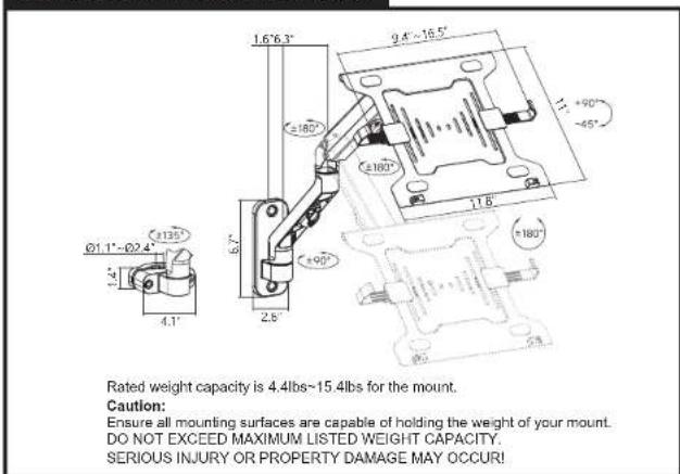
| Tilt Range | -45° to +90° |
| Swivel Range | Left/right adjustable |
| Rotation Range | 360° |
| Cable Management | Yes, clips on underside of arm |
| Installation | Professional installation recommended |
| Safety Note | Contains stored energy; use caution when releasing spring arm |
| Included Components | Wall Mount Plate, Pole Clamp, Spring Arm, Laptop Tray, Laptop Clamps, Hardware Kit, Decorative Covers |
| Support Contact | Phone: (855) 925-5668, Email: support@mount-it.com |
| Indoor Use Only | Yes |
| Maintenance Interval | Check every 3 months |
Frequently Asked Questions - MI-1765LT Mount-It!
User questions about MI-1765LT Mount-It!
0 question about this device. Answer the ones you know or ask your own.
Ask a new question about this device
Download the instructions for your Computer accessory in PDF format for free! Find your manual MI-1765LT - Mount-It! and take your electronic device back in hand. On this page are published all the documents necessary for the use of your device. MI-1765LT by Mount-It!.
USER MANUAL MI-1765LT Mount-It!
natural_image
Technical line drawing of a mechanical linkage assembly with a QR code below (no text or symbols on the diagram itself)
Please scan this QR code to visit the product page.
MONITOR MOUNT WITH WALL MOUNT PLATE, CLAMP AND LAPTOP TRAY

HAVE QUESTIONS?
Monday - Friday from 8:00am - 4:00pm PST

support@mount-it.com

(855) 925-5668

www.mount-it.com
Thank you for choosing Mount-It!
EN Read the entire instruction manual before you start installation and assembly. If you have any questions regarding any of the instructions or warnings, please contact M:un-12 for assistance.
CAUTION: Use with products heavier than the rated weights indicated may result in variability causing possible injury. Please closely follow the assembly instructions. Improved installation may result in demand or serious personnel injury.
- Please close to the assembly instructions. Improper installation may result, in damage or harm - Safety gear and proper tools must be used. This product should only be installed by professionals.
- This product is designed to be installed on solid concrete walls, masonry walls or wood stud walls.
- Make sure that the supporting surfaces will safely support the combined weight of the equipment and all attached hardware and components. Line the mounting screen provided and DO NOT OVER TIGHTEN mounting arrees.
* This product contains small items that could be a choking hazard if swallowed. Keep these items away from children.
• This product is intended for indoor use only. Using this product outdoors could wait to product failure and personal injury.
MPORTAN: Ensure that you have retained all parts absorbing to the component check at prior to installation. If any parts are missing or faulty, contact K-0014 for a parliament
MAINTENANCE: Check that the product is secure and sells to use at regular intervals (at least every three months).
The information is presented in Table 1. The authors and the members of the research committee are also to be identified as a member of the research committee, which has been identified as an independent director.
Mount and Accessories

Check carefully to make sure there are no missing or defective parts. Some hardware provided may not be used. Use the correct mounting hardware suitable for your installation.
CHOKING HAZARD. Package includes small parts.
Not for children under 3 years. Adult supervision is required.
Missing Parts? Call us at (855) 925-5668 and we will ship replacement parts free of charge.
DIMENSIONS & WEIGHT CAPACITY
Step 1
Step 1a-1
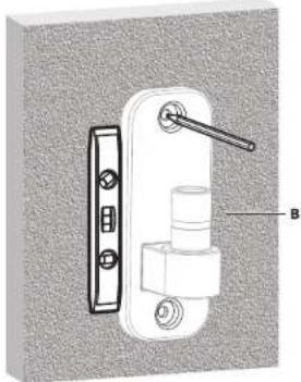
A. Wood Stud Mounting Option
With a stud finder locate the stud and center the Wall Mount Plate (#B) on the stud at the desired height. Using a bubble level to ensure straightness mark the center of the mounting holes with a pencil.
- Use a 3/16" drill bit and drill on the marked locations to a depth of 2.2". Secure the Wall Mount Plate (#B) to the wall using Lag Screws (#W-A) and Washers (#W-C). Tighten the screws until secure.


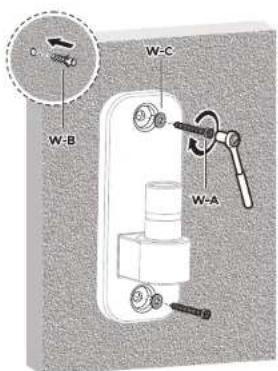
B. Concrete/Brick Mounting Option
- Using a bubble level to ensure straightness hold the Wall Mount Plate (#B) to the desired location on the wall and mark the center of the mounting holes with a pencil. - Use a 3/8" drill bit and drill on the marked locations to a depth of 2.4". Clear any dust and debris from the holes and insert the Concrete Anchors (#W-B). Secure the Wall Mount Plate (#B) to the wall using Lag Screws (#W-A) and Washers (#W-C). Tighten the screws until secure.

natural_image
Technical illustration of a door handle assembly with labeled component B (no text or symbols beyond label)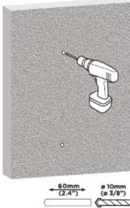
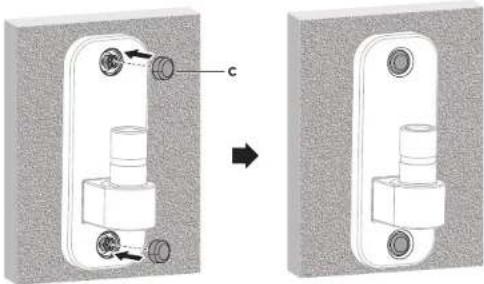
Step 1a-2
Insert Decorative Covers
- Insert the Decorative Covers (#C) into each of the bolt holes.
natural_image
Mechanical assembly diagram showing a valve mechanism before and after modification, with no visible text or symbols.Step 1b
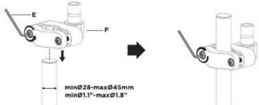
Pole Clamp Mounting Option
Attaching the Pole Clamp (Pole Diameters Between 1.1"-1.8")
• Using Hex Wrench (#E) loosen the two bolts on the Pole Clamp (#F) until the clamp opens wide enough to slide onto the pole.
- Move the Clamp to the desired height and tighten the bolts back down until secure.
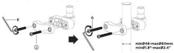
Attaching the Pole Clamp (Pole Diameters Between 1.8"-2.4")
- Using Hex Wrench (#E) remove the two bolts from the Pole Clamp (#F) and replace them with the Alternate Bolts (#G). After installing the alternate bolts, adjust the width of the clamp to be slightly larger than the pole.
- Move the Clamp to the desired height and tighten the bolts back down until secure.
Step 2
Attach the Spring Arm to the Mount

WARNING
STORED ENERGY
- The monitor arm is shipped compressed and under tension.
- When cutting the cable tie firmly hold and brace both parts using your hands as shown or ask for the assistance of another person.
- Failure to follow this process may result in personal injury or property damage.

- Place the end of the Spring Arm (#A) onto the end of the Wall Mount or Pole Mount. Tighten the bolt on the back of the Spring Arm to secure the arm to the mount.

natural_image
Technical diagram showing a mechanical assembly with a magnified inset highlighting a rotating component (no text or symbols present)Step 3
Step 3a-1
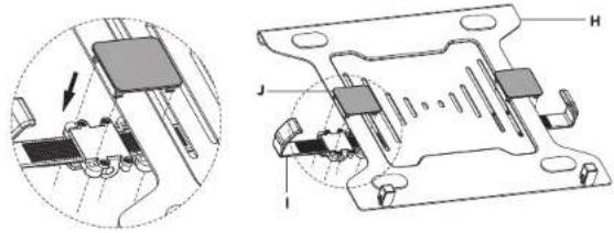
Attach the Clamps to the Laptop Tray
- Attach the Laptop Clamps (#I) to the Laptop Tray (#H) using Clamp Connectors (#J) as shown here. One end of the Clamp Connectors will pass through the outer slot on the Laptop Tray, while the other end will pass over the outer edge of the tray. Clip the Clamp Connectors into place on the Clamps to secure them to the Tray.
natural_image
Technical diagram of a mechanical assembly with labeled components (no readable text or symbols)Step 3a-2
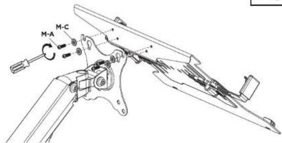
Attach the Laptop Tray to the Spring Arm
- Attach the Laptop Tray (#H) to the top 4 bolt holes on the Spring Arm (#A) using Bolts (#M-A) and Washers (#M-C).

Step 3a-3
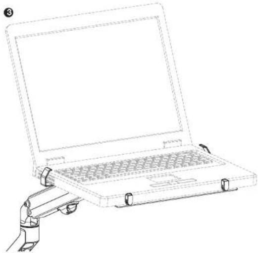
Insert the Laptop
- Flip the tab on the Laptop Clamps up to release the sliding arms.
- Flip the small arms on the front of the Laptop Tray up so that they are perpendicular to the laptop surface.
- Place the laptop on the tray, slide the Clamp arms in until they are snug against the side of the laptop, and press the tabs back down to secure the arms in place. Cables can be run through the cable management clips on the underside of the spring arm.

natural_image
Line drawing of a laptop with a robotic arm attachment (no text or symbols)Step 3b-1
Optional Monitor Instructions: Install the Top Bolts to the Monitor
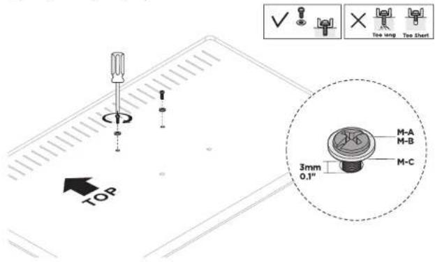
- Select the appropriate size mounting bolt (#M-A, M-B) for your display's mounting holes and verify the length of the VESA bolt is not too long. If you are unsure of the correct bolt size for your display refer to your user manual or contact the monitor manufacturer for sizing information.
• After selecting the appropriate bolt install the top two bolts and washers (#M-C) to the monitor leaving a gap of approximately 0.1" (3mm).
Step 3b-2
Attaching the Monitor
- Hang the monitor onto the top of the VESA plate as shown.
- Install the lower two bolts and washers (#M-C) through the lower holes. Tighten all 4 bolts until secure, do not over tighten.

Step 4
Final Adjustments
- Cables can be run through the cable management clips on the underside of the spring arm.
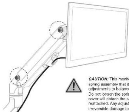
CAUTION: This monitor mount utilizes a mechanical spring assembly that does not require tension adjustments to balance the weight of the monitor. Do not loosen the spring cover bolts. Removing the cover will detach the spring and it will be unable to be reattached. Any adjustment to these parts will cause irreversible damage to the monitor arm.
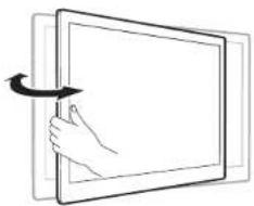
- The viewing angle can be adjusted in the range of -45^ to +90^ , and the screen can be rotated 360^ . Each joint can swivel left or right for alternate viewing angles.
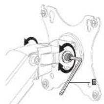
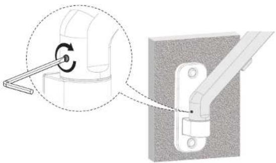
natural_image
Mechanical assembly diagram showing a rotating component with labeled point E (no text or symbols beyond label)Note: Adjust to the desired angle then tighten the screws using the tool as shown, alternating from each screw as you tighten them.
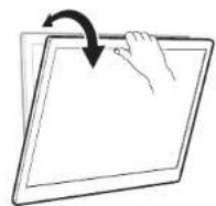
natural_image
Line drawing of a hand pressing a button on a screen, with an arrow indicating rotation (no text or symbols)
Visit us at www.mount-it.com for product registration and warranty information.
Our US based customer service team is standing by to answer any questions you have about your Mount-It! product.
Available by phone Monday - Friday from 8:00am to 4:00pm PST.
Chat live with an agent on our website!

support@mount-it.com

(855) 925-5668

www.mount-it.com
- MONITOR MOUNT WITH WALL MOUNT PLATE, CLAMP AND LAPTOP TRAY
- Thank you for choosing Mount-It!
- Step 1
- Step 1a-1
- Wood Stud Mounting Option
- Concrete/Brick Mounting Option
- Step 1a-2
- Insert Decorative Covers
- Step 1b
- Pole Clamp Mounting Option
- Step 2
- Attach the Spring Arm to the Mount
- WARNING
- STORED ENERGY
- Step 3
- Step 3a-1
- Attach the Clamps to the Laptop Tray
- Step 3a-2
- Attach the Laptop Tray to the Spring Arm
- Step 3a-3
- Insert the Laptop
- Step 3b-1
- Optional Monitor Instructions: Install the Top Bolts to the Monitor
- Step 3b-2
- Attaching the Monitor
- Step 4
- Final Adjustments
Brand : Mount-It!
Model : MI-1765LT
Category : Computer accessory