IFB-244 Series - Computers Planet - Free user manual and instructions
Find the device manual for free IFB-244 Series Planet in PDF.

User questions about IFB-244 Series Planet
0 question about this device. Answer the ones you know or ask your own.
Ask a new question about this device
Download the instructions for your Computers in PDF format for free! Find your manual IFB-244 Series - Planet and take your electronic device back in hand. On this page are published all the documents necessary for the use of your device. IFB-244 Series by Planet.
USER MANUAL IFB-244 Series Planet
Industrial 2-channel
Optical Fiber Bypass Switch
IFB-244 Series
User's Manual
Table of Contents
- Package Contents.... 3
- Product Features 4
- Product Specifications....5
4 Hardware Introduction....7
4.1 Three-View Diagram....7
4.2 LED Definition ....10
4.3 Wiring the Power Inputs....10 - Hardware Installation....12
5.1 DIN-rail Mounting Installation 12
5.2 Wall-mount Plate Mounting....12
5.3 Side Wall-mount Plate Mounting....13 - Optical Fiber and Power Connections....14
6.1 Optical Fiber Connection....14
6.2 Power Connection ....16
6.3 Recovering Communication from Power Failure....16
Customer Support....19
1. Package Contents
Thank you for purchasing PLANET Industrial 2-channel Optical Fiber Bypass Switch, IFB-244 Series. In the following section, the term "Optical Bypass Switch" means the IFB-244 Series.
The descriptions of these models are as follows:
| Models Optic Connectors Optic | Mode Optic Wavelength | ||
| IFB-244-SLC 4 | x Duplex LC | Single Mode | 1310nm & 1550nm |
| IFB-244-SSC 4 | x Duplex SC | ||
| IFB-244-MLC 4 | x Duplex LC | Multimode 85 | 0nm & 1300nm |
| IFB-244-MSC 4 | x Duplex SC | ||
Open the box of the Optical Bypass Switch and carefully unpack it. The box should contain the following items:
| Optical Bypass Switch x 1 User's Manual x 1 | |
 |  |
| DIN-rail Kit Wall-mount Kit | |
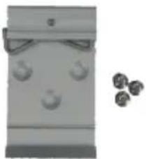 |  |
If any of these are missing or damaged, please contact your dealer immediately; if possible, retain the carton including the original packing material, and use them again to repack the product in case there is a need to return it to us for repair.
2. Product Features
Physical Port
- 2-channel duplex or 4-channel simplex fiber connection with optical bypass function
● Supports 100Gbps/40Gbps/10Gbps/1Gbps and 100Mbps fiber connections
● Available in Single mode or Multimode
● Available in LC/SC connectors
Optical Bypass
● Bypass switch time <8ms
- Low return loss
● Throughput not affected and no extra delay
- Increased reliability on critical network links
Industrial Case and Installation
● IP30-rated metal housing
- 9V\~48V DC or 24V AC redundant power inputs with reverse polarity protection
● Low power consumption
- Connective removable terminal block
● Supports 6000 VDC Ethernet ESD protection
- -40 to 75 degrees C operating temperature
● DIN-rail and wall-mount designs
● Free fall, shock-proof and vibration-proof for industries
- Product Specifications
| Model | IFB-244-SLC | IFB-244-SSC | IFB-244-MLC | IFB-244-MSC |
| Hardware Specifications | ||||
| Optic Interfaces | 4 x Duplex LC | 4 x Duplex SC | 4 x Duplex LC | 4 x Duplex SC |
| Optic Mode Single Mode Multimode | ||||
| Optic Wavelength 1310nm & 1550nm 850nm | & 1300nm | |||
| Operating Wavelength | 1260~1620nm | 850nm±40 / 1300nm±40 | ||
| Bypass Return Loss | >50dB >35dB | |||
| Bypass Insertion Loss | Typical: 1.0dB Max: 1.5dB | |||
| Bypass Switching Time | <8ms | |||
| Speed 100Gbps/40Gbps/10Gbps/1Gbps/100Mbps | ||||
| ESD Protection Air: | 8kV, Contact: 6kV | |||
| Enclosure IP30 metal case | ||||
| Installation DIN-rail | kit and wall-mount kit | |||
| Connector | Removable 6-pin terminal block for power input Pin 1/2 for Power 1, Pin 5/6 for Power 2 Pin 3/4 for fault alarm, | |||
| Alarm | One relay output for power failure. Alarm relay current carry ability:1A@24V DC | |||
| LED Indicator | Power 1 (Green), Power 2 (Green), Fault (Red) Normal operation (Green) | |||
| Dimensions (W x D x H) | 32 x 87 x 135 mm | 50 x 87 x 135 mm | 32 x 87 x 135 mm | 50 x 87 x 135 mm |
| Weight 405g | ||||
| Power Requirements | Dual 9-48V DC with polarity reverse protection function24V AC | |||
| Power Consumption | 0.54 watts/1.84BTU | |||
| Cabling 9/125μm 50/125μm | ||||
| Standards Conformance | ||||
| Regulatory Compliance | FCC Part 15 Class ACE | |||
| Stability Testing | IEC60068-2-32 (free fall)IEC60068-2-27(shock)IEC60068-2-6 (vibration) | |||
| Environment | ||||
| Operating Temperature | -40~75 degrees C | |||
| Storage Temperature | -40~85 degrees C | |||
| Humidity 5~95% (non-condensing) | ||||
4 Hardware Introduction
4.1 Three-View Diagram
The three-view diagram of the Optical Bypass Switch consists of optical fiber connector and one removable 6-pin terminal block. The LED indicators are also located on the front panel.
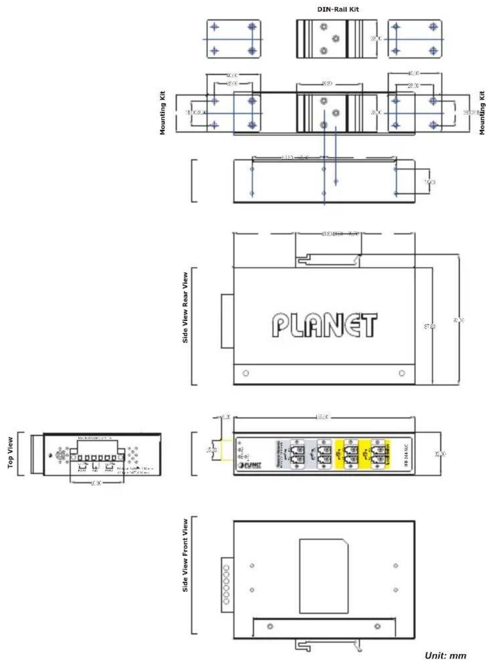
Figure 4-1: IFB-244-SLC and IFB-244-MLC Three-View Diagram

Unit: mm
Figure 4-2: IFB-244-SSC and IFB-244-MSC Three-View Diagram
■ Front View

text_image
P1 P2 Fault Normal Remote Network A TX RX B TX RX A TX RX B TX RX Local Switch IFB-244-SLCFigure 4-3: IFB-244-SLC and IFB-244-MLC Front View

text_image
P1 P2 Fault Normal Remote Network A TX RX B TX RX A TX RX B TX RX Local Switch IFB-244-SSCFigure 4-4: IFB-244-SSC and IFB-244-MSC Front View
4.2 LED Definition
■ System
| LED Color Function | |||
| P1 Green | Lit: Power 1 is active. | ||
| Off: Power 1 is inactive. | |||
| P2 Green | Lit: Power 2 is active. | ||
| Off: Power 2 is inactive. | |||
| FAULT Red | Lit: | Hardware indicates either Power 1 or Power 2 has no power. | |
| Off: No failure. | |||
■ STATE
| LED Color Function | |||
| Normal | Green | Lights: | To indicate the Bypass Switch is operating in Normal mode with power input. |
| Off: | To indicate the Bypass Switch is operating in Bypass mode with power failure. | ||
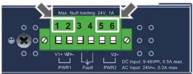
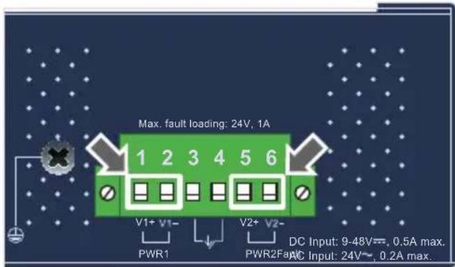
4.3 Wiring the Power Inputs
The upper panel of the Optical Bypass Switch indicates an inlet power socket and consists of one terminal block connector within 6 contacts. Please follow the steps below to insert the power wire.
- Insert positive/negative DC power wires into Contacts 1 and 2 for Power 1, or Contacts 5 and 6 for Power 2. Figure 4-5 and 4-6 show PWR1 and PWR2 of the Optical Bypass Switch.
■ IFB-244-SLC/IFB-244-MLC: 9\~48V DC or 24V AC
text_image
Max. fault loading: 24V, 1A 1 2 3 4 5 6 V1+ V2+ PWR1 Fault PWR2 V2- DC Input: 9-48V~, 0.5A max. AC Input: 24V~, 0.2A max.Figure 4-5: IFB-244-SLC/IFB-244-MLC upper panel
■ IFB-244-SSC/IFB-244-MSC: 9\~48V DC or 24V AC
text_image
Max. fault loading: 24V, 1A 1 2 3 4 5 6 V1+ V1- PWR1 V2+ V2- DC Input: 9-48V~, 0.5A max. PWR2Fa AC Input: 24V~, 0.2A max.Figure 4-6: IFB-244-SSC/IFB-244-MSC upper panel
- Tighten the wire-clamp screws for preventing the wires from loosening.

natural_image
Close-up of a green electronic component with four circular slots, one highlighted in black (no visible text or symbols)1 2 3 4 5 6
V1+ V1- V2+ V2-
Power 1 Fault Power 2
Figure 4-7: PWR1 & PWR2 pins of terminal block.

The wire gauge for the terminal block should be in the range from 12 to 24 AWG.

text_image
Warning symbol image with exclamation mark inside a triangleWhen performing any of the procedures like inserting the wires or tightening the wire-clamp screws, make sure the power is OFF to prevent from getting an electric shock.
5. Hardware Installation
This section describes the functionalities of the Optical Bypass Switch's components and guides you to installing it on the DIN rail and wall. Please read this chapter completely before continuing.

This following pictures guide you to how to install the device, and the device is not IFB-244 Series.
5.1 DIN-rail Mounting Installation
text_image
1 2
natural_image
Black industrial electronic device with multiple ports and a green connector attached to its side (no visible text or symbols)5.2 Wall-mount Plate Mounting

natural_image
Close-up of hands using a red screwdriver to adjust a black plastic component (no text or symbols visible)
natural_image
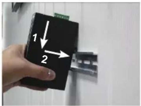
Black industrial electronic device with green connectors and ports, mounted on a wall (no visible text or symbols)5.3 Side Wall-mount Plate Mounting

natural_image
Close-up of hands using a screwdriver to adjust or install a black electronic component (no visible text or symbols)
natural_image
Black industrial electronic device with green connector and 'Pancity' branding (no readable text or symbols beyond branding)5.4 Grounding the Device
Uses MUST complete grounding wired with the device; otherwise, a sudden lightning could cause fatal damage to the device. EMD (Lightning) DAMAGE IS NOT CONVERED UNDER WARRANTY.
6. Optical Fiber and Power Connections
6.1 Optical Fiber Connection
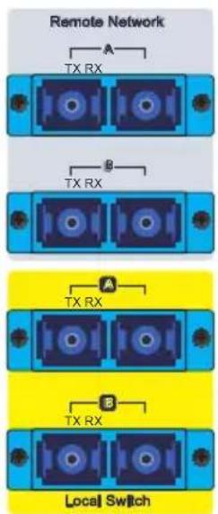
The IFB-244 series is equipped with a total of 4 duplex fiber connectors and they are separated into two groups - Remote Network channels and Local Switch channels.
text_image
Remote Network A TX RX B TX RX A TX RX B TX RX Local Switch■ Remote Network group has 2 fiber channels that are used to connect to the other two remote fiber Ethernet switches.
■ Local Switch group has 2 fiber channels that are used to connect to the local fiber Ethernet switch.
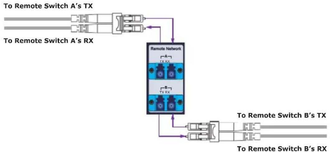
■ Connecting to the Remote Network with Duplex Fiber cables
flowchart
graph TD
    A["To Remote Switch A's TX"] --> B["To Remote Switch A's RX"]
    B --> C["Remote Network"]
    C --> D["To Remote Switch B's TX"]
    C --> E["To Remote Switch B's RX"]
    D --> F["To Remote Switch B's TX"]
    E --> G["To Remote Switch B's RX"]
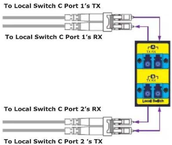
■ Connecting to the Local Switch
flowchart
graph TD
    A["To Local Switch C Port 1's TX"] --> B["Local Switch"]
    C["To Local Switch C Port 1's RX"] --> B
    D["To Local Switch C Port 2's RX"] --> B
    E["To Local Switch C Port 2's TX"] --> B
    B --> F["TX RX"]
    B --> G["TX RX"]
    B --> H["Local Switch"]
■ Connecting to the Remote Network with Simplex Fiber Cables (WDM/Bi-di)

flowchart
graph TD
    A["To Remote Switch A's WDM SFP"] --> B["Remote Network"]
    B --> C["To Remote Switch B's WDM SFP"]
    B --> D["TX RX Port 1"]
    B --> E["TX RX Port 2"]
    B --> F["TX RX Port 3"]
    B --> G["TX RX Port 4"]
■ Connecting to the Local Switch
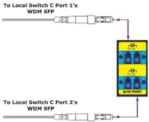
flowchart
graph TD
    A["To Local Switch C Port 1's WDM SFP"] --> B["Local Switch"]
    B --> C["TX RX"]
    B --> D["A"]
    B --> E["B"]
    B --> F["Local Switch"]
    G["To Local Switch C Port 2's WDM SFP"] --> H["Local Switch"]
    H --> I["TX RX"]
    H --> J["A"]
    H --> K["B"]
    H --> L["B"]
6.2 Power Connection
The IFB-244 Series is expected to be powered from the same power source as the Local Switch to ensure power system failure makes the IFB-244 Series change to Bypass mode. Make the IFB-244 Series share the same power source as the Local Switch.
6.3 Recovering Communication from Power Failure
| Operation Mode | Power Source | State LED | Optical Traffic Route |
| Normal Mode | Power on | Normal LED lit on | IFB-244 forwards packets between two remote network switches and the local switch. |
| Bypass Mode | Power off | Normal LED lit off | IFB 244 directly forwards packets between two remote networks switches and bypass the local switch. |
■ Normal Mode

flowchart
graph TD
    A["Switch A"] -->|Link good| B["IFB-244-S1C"]
    B -->|Link good| C["Switch B"]
    B -->|Power good| D["Switch C"]
    D -->|Link good| B
    B -->|Power good| A
    style A fill:#f9f,stroke:#333
    style B fill:#ccf,stroke:#333
    style C fill:#cfc,stroke:#333
■ Bypass Mode
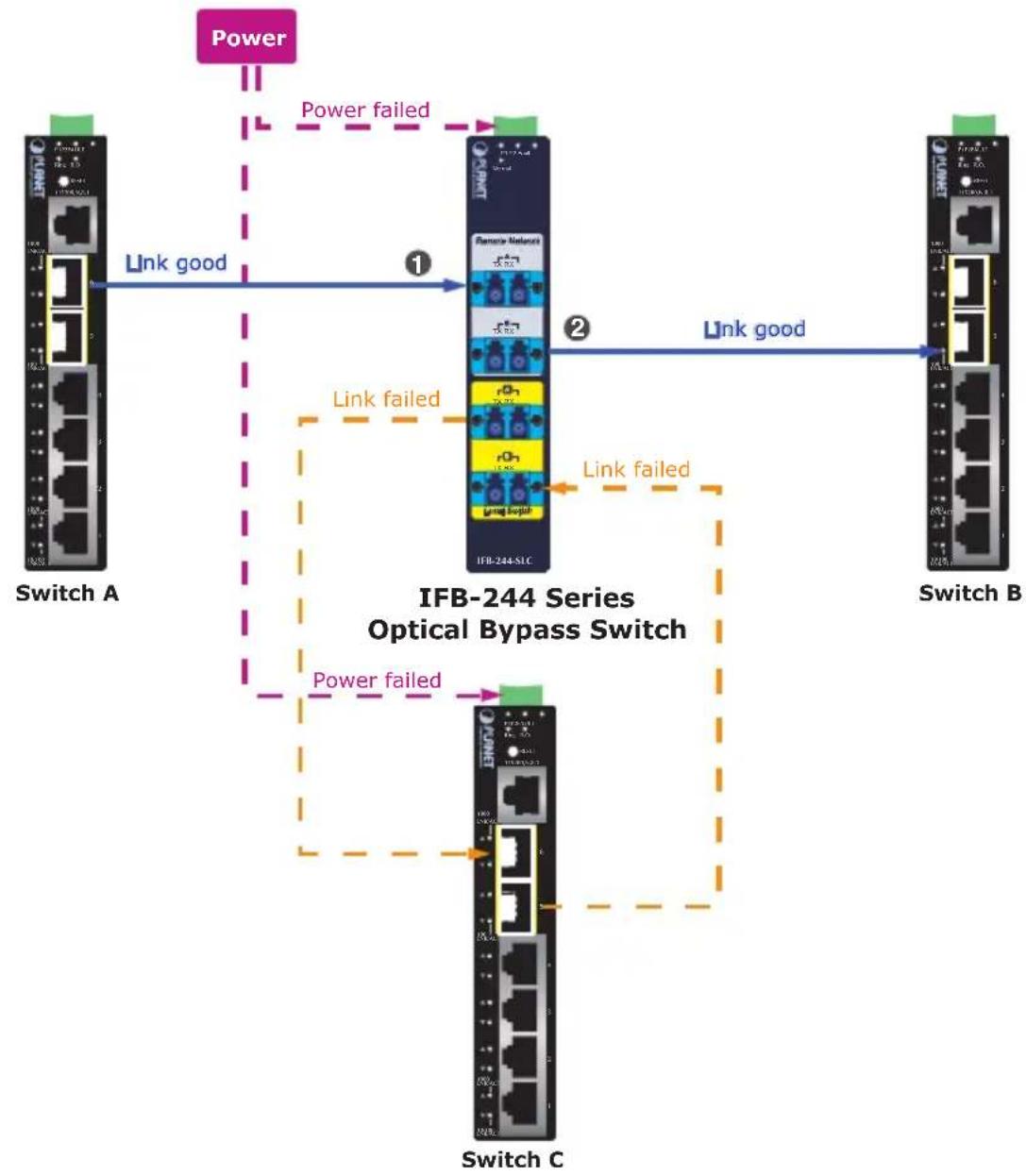
flowchart
graph TD
    A["Switch A"] -->|Link good| B["IFB-244-S1C"]
    B -->|Link good| C["Switch B"]
    B -->|Power failed| D["Power"]
    D -->|Power failed| A
    B -->|Link failed| E["Switch C"]
    E -->|Link failed| B
    style A fill:#f9f,stroke:#333
    style B fill:#ccf,stroke:#333
    style C fill:#cfc,stroke:#333
    style E fill:#fcc,stroke:#333
Customer Support
Thank you for purchasing PLANET products. You can browse our online FAQ resource on PLANET web site first to check if it could solve issue. If you need more support information, please contact PLANET switch support team.
PLANET online FAQs: http://www.planet.com.tw/en/support/faq.php
Switch support team mail address: support @planet.com.tw
Copyright © PLANET Technology Corp. 2019.
Contents are subject to revision without prior notice.
PLANET is a registered trademark of PLANET Technology Corp.
All other trademarks belong to their respective owners.
EC Declaration of Conformity
For the following equipment:
*Type of Product : Industrial 2-channel Optical Fiber Bypass Switch
*Model Number : IFB-244-SLC, IFB-244-MLC, IFB-244-SSC, IFB-244-MSC
* Produced by:
Manufacturer's Name : Planet Technology Corp.
Manufacturer's Address : 10F., No.96, Minquan Rd., Xindian Dist.,
New Taipei City 231, Taiwan R.O.C.
is herewith confirmed to comply with the requirements set out in the Council Directive on the Approximation of the Laws of the Member States relating to Electromagnetic Compatibility Directive on (2014/30/EU).
For the evaluation regarding the EMC, the following standards were applied:
EN 55032 (2015 + AC:2016)
EN 55024 (2010 + A1: 2015)
EN 55035 (2017)
Responsible for marking this declaration if the:
Manufacturer ☐ Authorized representative established within the EU
Authorized representative established within the EU (if applicable):
Company Name: Planet Technology Corp.
Company Address: 10F., No.96, Minquan Rd., Xindian Dist., New Taipei City 231, Taiwan R.O.C.
Person responsible for making this declaration
Name, Surname Kent Kang
Position / Title : Director
Taiwan
Place
Jan. 14, 2019
Date
font lang
Legal Signature