
IRI6WE3 - Cap ARC - Free user manual and instructions
Find the device manual for free IRI6WE3 ARC in PDF.

| Product Type | Integrated Canopy Rangehood |
| Model | IRI6WE3 |
| Brand | ARC |
| Width | 600 mm (fits 600 mm overhead cupboard) |
| Installation Height | Min 65 cm, max 75 cm above cooktop |
| Mounting | Fully integrated inside overhead cupboard |
| Ducting Options | Ducted or recirculating |
| Duct Diameter | Minimum 150 mm |
| Number of Speeds | 3 (Low, Mid, High) |
| Lighting | 2x 20W 12V G4 halogen bulbs (push button control) |
| Control Type | Push button back-lit electronic |
| Grease Filters | Removable, washable (dishwasher safe up to 60°C), clean every 4 weeks |
| Carbon Filters | Optional, code CF160 (2 supplied), replace every 4-6 months |
| Material | Metal (body and motor housing) |
| Electrical Supply | Unplug before maintenance, voltage not specified |
| Warranty | 2 years parts and labour (excluding halogen bulbs) |
| Safety Features | Must be installed by qualified person; avoid flambé cooking; ensure adequate ventilation |
| Accessories Included | Mounting bracket, duct spigot, 150 mm flexible duct, nylon ties |
| Service Contact | Toll Free 1800 805 300 |
| Country of Origin | Not specified |
Frequently Asked Questions - IRI6WE3 ARC
User questions about IRI6WE3 ARC
0 question about this device. Answer the ones you know or ask your own.
Ask a new question about this device
Download the instructions for your Cap in PDF format for free! Find your manual IRI6WE3 - ARC and take your electronic device back in hand. On this page are published all the documents necessary for the use of your device. IRI6WE3 by ARC.
USER MANUAL IRI6WE3 ARC
600mm Intergrated Canopy Manual
MODEL
IRI6WE3
HOME APPLIANCES
Dear Customer,
We thank you for choosing this quality appliance and hope you enjoy many years of reliable service.
Please ensure this manual is read carefully before installation and use. Keep this manual in a safe and accessible location should future reference be required.
Regards
Home Appliances
CONTENTS
Contents 1
Safety Warnings 2
Dimensions 3
Installation 4-8
Operation 9
Maintenance and Cleaning 10-11
Service 11
SAFETY WARNINGS
- Installation of this Integrated Canopy Rangehood must be carried by a qualified and competent installer.
- The manufacturer disclaims and liability for any damage or injury caused as a result of not following instruction of installation contained in this instruction manual.
- This Integrated Canopy Rangehood is not intended for use by young children or infirm persons without supervision.
- Young children should be supervised to ensure they do not play with this Integrated Canopy Rangehood.
- To avoid possible electric shock this Integrated Canopy Rangehood should be unplugged before any maintenance or cleaning is carried out.
- This Integrated Canopy Rangehood cannot be installed in an external environment.
- The Grease Filters should be cleaned at least once a month to avoid the risk of fire.
- Flambe cooking cannot be carried out under the Integrated Canopy Rangehood and is not recommended for use over Barbeques.
- Ducting must be independent from any other form of ducting of other household heating sources.
- Ducting into wall cavities is prohibited unless the cavity has been designed for this purpose
- Lit gas burner should never remain uncovered or on when there is no pan present due to the risk of fire.
- Adequate ventilation of the room is required when the cooker hood is used at the same time as appliances burning gas or other fuels.
DIMENSIONS
Dimensions of IRI6WE3 and IRI9WE3

INSTALLATION
The IRI6WE3 and IRI9WE3 are designed to be installed fully integrated into an overhead cupboard as pictured below. The IRI6WE3 is suited for a 600mm cupboard and the IRI9WE3 suited for a 900mm cupboard.
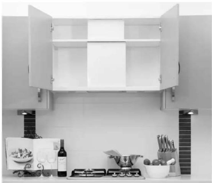
natural_image
Black-and-white photo of a kitchen cabinet with open doors and a stove on the counter (no visible text or symbols)Installation of the IRI9WE3 Integrated rangehood in an overhead cupboard
Height Requirement
The minimum installation height requirement above the highest point of the cooktop to the rangehood filter should be no less than 65cm. For the best performance, the maximum height should not exceed 75cm. (Fig. 1)

Fig. 1
INSTALLATION - Position of Mounting Bracket
The Integrated Rangehood is mounted to the rear of the overhead cupboard. Supplied with the rangehood is a mounting bracket (Fig. 2)
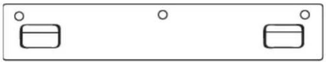
natural_image
Simple diagram with two rectangular shapes and three circles, no text or symbols presentFig. 2
Prior to installation, check the measurement from the screw holes in the mounting bracket to the base of the rangehood. Achieve this by placing the mounting bracket onto the rear of the Integrated rangehood and measure from base of rangehood to the mid point of the centre screw hole on the mounting bracket. This may vary slightly to the dimensions mentioned in Fig. 3. and should be the one you use to ensure the base of the rangehood is level with the base of the overhead cupboards.
Centre the mounting bracket on the rear panel of the overhead cupboard. Ensure the mounting bracket is level and mark the 3 screw holes positions. Drill pilot holes into the rear panel at the positions you have marked. Relocate mounting bracket and fasten it with appropriate screws to the rear cupboard panel. Before tightening completely check the level is correct. (Fig. 3)

INSTALLATION – Fitting of Integrated Rangehood
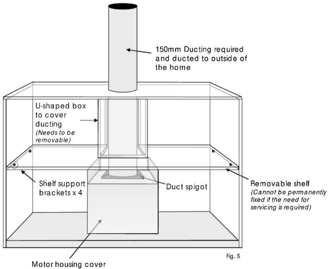
Fit 150mm duct spigot (pictured below) with the four 8mm screws provided over the rectangular hole located at the top rear of the integrated rangehood. Fit 150mm flexible ducting (pictured below), supplied, to the ducting spigot, Using one of the nylon ties, supplied, secure the ducting to the duct spigot.
A hole or cutout needs to be made in the centre rear of the removable shelf positioned above the integrated rangehood for the ducting to go through.

natural_image
Close-up of a metallic mechanical component with circular top and flange (no visible text or symbols)
natural_image
Close-up of a cylindrical container filled with granular material (no visible text or symbols)150mm duct spigot 150mm flexible ducting
Mount the Integrated Rangehood onto the two tabs on the mounting bracket into the two matching slots located at the rear of the rangehood. (Fig. 4)
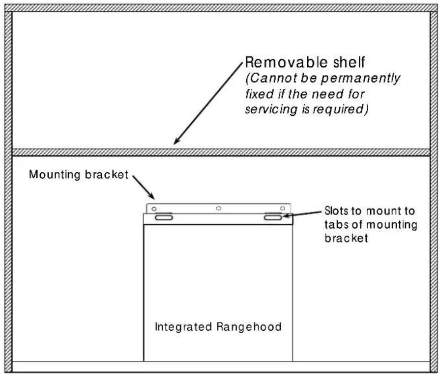
Fig. 4
INSTALLATION – Ducted or Re-circulating
The integrated rangehood can be installed in either ducted or re-circulating method. The integrated rangehood is supplied with a small length of flexible duct, although may not be sufficient in all installations. The installer needs to determine the method in which the rangehood will be installed and may need to supply the appropriate components to duct the rangehood correctly.
Ducted installation
Ducting components will need to be supplied by the installer as every installation can be different. The size of the duct pipe needs to be no less than 150mm in diameter. Use of smaller diameter duct pipe will effect performance and create air noise from the rangehood.
The shelf above the top of the rangehood needs to removable, should the need for servicing be required at a later date. The shelf needs to be located no less than 400mm above the top of the rangehood as the metal motor housing supplied needs to be put in place after the rangehood has been installed. Above the shelf a U-shaped box can be made to cover the duct so it cannot be seen when the overhead cupboard is open. (Fig.5)
INSTALLATION – Ducted or Re-circulating
Re-circulation installation
150mm flexible duct is provided with the integrated rangehood for re-circulating installation. This type of installation can be executed to the top of a cupboard or through a bulkhead above the cupboard. In both cases a mesh cover will need to be supplied by the installer to keep out insects and vermin. The size of the duct pipe needs to be no less than 150mm in diameter. Use of smaller diameter duct pipe will effect performance and create air noise from the rangehood.
The shelf above the top of the rangehood needs to removable, should the need for servicing be required at a later date. The shelf needs to be located no less than 400mm above the top of the rangehood as the metal motor housing supplied needs to be put in place after the rangehood has been installed. Above the shelf a U-shaped box can be made to cover the duct so it cannot be seen when the overhead cupboard is open. (Fig.6)
Carbon filters may be required to reduce any fumes or smells being re-directed back into the kitchen environment. Call 1800 805 300 to order carbon filters if required.
Carbon Filter code - CF160 (2 supplied)

OPERATION
The integrated rangehood is fitted with push button Back-lit electronic controls.
There is 1 light push button and 3 speed push buttons, Low, Mid and High to control the air flow speeds. (Fig. 7)
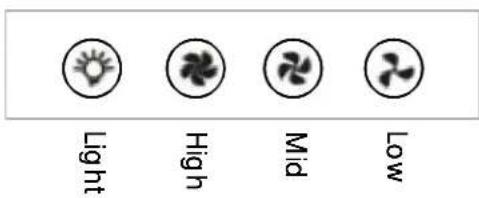
Fig. 7
Light Control
To turn ON the halogen lights, depress the Light electronic push button once. When ON, the back lit push button will glow blue. To turn lights OFF, depress the Light electronic push button again.
Speed Control
To turn ON the rangehood, depress either the Low, Mid or High electronic push buttons. When ON, the back lit push button will glow blue to indicate your selection. You may wish to start on Low prior to cooking commencing and at any time switch to Mid or High without having to turn off the Low speed first. You can depress any speed at any time and it will cancel the previous speed chosen. To turn of OFF the rangehood depress the indicated electronic push button again.
At the end of cooking it is recommended to run the rangehood on low for up to 10 minutes to help remove any residual fumes and smoke produced during cooking.
MAINTENANCE and CLEANING
WARNING
ALWAYS un-plug the rangehood PRIOR to any maintenance or cleaning being carried out, to avoid possible electric shock.
To ensure long lasting performance and efficiency, regular maintenance and cleaning of your integrated rangehood should be performed.
Replacing Halogen Bulbs
After many hours of operation halogen bulbs may require replacement. This can be done by the owner. Please follow the following steps to conduct this procedure.
Halogen bulb type - 20W 12V G4
NOTE: Replacement of halogen light bulbs are not covered under the 2 years parts and labour warranty.
natural_image
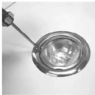
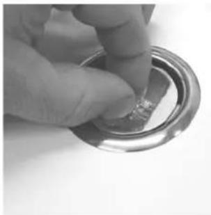
Close-up of a metallic spoon holding a transparent circular object, possibly a container or lamp (no text or symbols visible)Step 1. Remove lamp cover using a small screwdriver, there are 4 points to assist in easy removal

natural_image
Close-up of two glass components with tweezers, one containing a small metallic sphere (no text or symbols visible)Step 2. Place cover in safe place as it is made from glass
natural_image
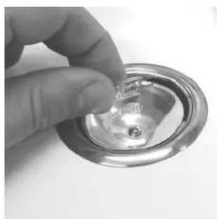
Close-up of a hand holding a small metallic ring component (no text or symbols visible)Step 3. Grip the halogen bulb and pull from holder
natural_image
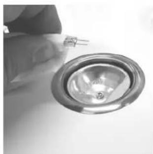
Close-up of a hand holding a small metallic object with a small hole, partially enclosed in a circular frame (no text or symbols visible)Step 4. Remove lamp and discard in a safe and proper manner.
natural_image
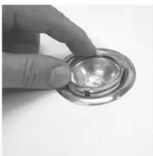
Close-up of a hand holding a metallic circular component with a small inset showing a small symbol (no text or labels visible)Step 5. Using a tissue or gloves to protect bulb, fit new halogen bulb. (Oil from the skin can affect halogen bulbs)
natural_image
Hand holding a small metallic object with a reflective surface (no text or symbols visible)Step 6. Re-fit lamp cover carefully. Ensure it is securely positioned.
MAINTENANCE and CLEANING
WARNING
ALWAYS un-plug the rangehood PRIOR to any maintenance or cleaning being carried out, to avoid possible electric shock.
Cleaning of Grease Filter
We recommend cleaning of the grease filter to be done at least every 4 weeks. Cleaning of the grease filter ensures continued performance of the rangehood.
Remove the grease filter and soak in warm to hot water containing liquid detergent. Soak for at least 5 minutes to break down the grease build-up. Without applying too much pressure use a soft brush to remove stubborn grease residue. Rinse under clean water. Ensure that the filter is completely dry before re-fitting to rangehood.
The grease filter can be cleaned in the dishwasher on a normal wash program at a temperature around 60 Degrees Celsius. NOTE: Some dis-colouration of the grease filter may occur when cleaned in the dishwasher.
Cleaning of the Rangehood
As cooking can create a great deal of grease, we recommend that the rangehood body and motor housing area be cleaned every 3 months. Ensure that non caustic, abrasive detergents or harsh chemicals are not used to clean the rangehood as this could cause damage.
Regularly cleaning the rangehood will ensure you get the best performance of your appliance. Use hot water, detergent and a soft cloth to carry out the cleaning of your rangehood. DO NOT excess water during cleaning and keep water away from the motor and other electronic components.
Avoid cleaning immediately after using the rangehood as components and lights could still be hot. Clean the rangehood when it has not been in operation.
Carbon Filters
Carbon Filters CANNOT be washed and re-used. Carbon filters, if used, require replacement every 4 to 6 months depending on usage.
SERVICE
Should you experience any problems with your rangehood, please un-plug immediately and as soon as possible, contact Service on
Toll Free 1800 805 300
Alternatively you can book a service call on our website
www.customersupport.integratedappliancegroup.com.au


- 600mm Intergrated Canopy Manual
- CONTENTS
- SAFETY WARNINGS
- DIMENSIONS
- INSTALLATION
- Height Requirement
- INSTALLATION - Position of Mounting Bracket
- INSTALLATION – Fitting of Integrated Rangehood
- INSTALLATION – Ducted or Re-circulating
- Ducted installation
- Re-circulation installation
- OPERATION
- Light Control
- Speed Control
- MAINTENANCE and CLEANING
- WARNING
- Replacing Halogen Bulbs
- Cleaning of Grease Filter
- Cleaning of the Rangehood
- Carbon Filters
- SERVICE
Brand : ARC
Model : IRI6WE3
Category : Cap