
3700P - Meter Daytronic - Free user manual and instructions
Find the device manual for free 3700P Daytronic in PDF.

| Product Type | Counter with Peak Capture Option |
| Brand | Daytronic |
| Model | 3700P |
| Category | Counter |
| Peak Modes | +Peak, -Peak, Max+Min, TIR |
| Analog Signal Source | FAST or SELECT (low-pass filtered) |
| Display | Front panel, selectable Live or Peak reading |
| Analog Output | ±5 V or ±10 V full scale, capacitive memory |
| Logic I/O | 8-pin connector: Track/Peak, Hold, Display select, TARE, Have Peak output |
| Threshold Adjustment | Potentiometer, 1-8% of full scale (for Have Peak detection) |
| Backout Level (Switch 7) | 0.1% or 1% of full scale |
| Dip Switch Configuration | 7-position, sets analog source, peak mode, display, TARE function, threshold display, backout level |
| Front Panel TARE Switch | Configurable: Normal TARE, Peak Reset, or Live/Peak display toggle |
| Power Supply | Derived from main 3700 unit (typically 115/230 VAC) |
| Dimensions (approx.) | Standard 1/8 DIN (96 x 48 mm) or rack mount |
| Weight (approx.) | 0.5 kg (1.1 lbs) |
| Operating Temperature | 0 to 50°C (32 to 122°F) |
| Storage Temperature | -20 to 70°C (-4 to 158°F) |
| Humidity | Up to 95% non-condensing |
| Accessories Included | User manual, connector plug |
| Compatibility | All 3700 series meters except 3741 Horsepower |
| Maintenance | No user-serviceable parts; clean with dry cloth |
| Safety | Designed for indoor use; follow main unit safety instructions |
| Spare Parts / Repairability | Contact Daytronic for service; no field-replaceable parts listed |
Frequently Asked Questions - 3700P Daytronic
User questions about 3700P Daytronic
0 question about this device. Answer the ones you know or ask your own.
Ask a new question about this device
Download the instructions for your Meter in PDF format for free! Find your manual 3700P - Daytronic and take your electronic device back in hand. On this page are published all the documents necessary for the use of your device. 3700P by Daytronic.
USER MANUAL 3700P Daytronic
1. General Description
The "P" option of the 3700 Series Meter is an added function card which provides the ability of the meter to capture and hold + Peak, -Peak, Max-Min or TIR value that originates from the base 3700 instrument. Any 3700 (except Horsepower 3741) can accommodate the "P" option. Peak Mode signals are captured in real-time analog capacitive memory and are available for display and analog output monitoring. Only one of the following four separate modes can be configured for the Peak Capture operation.
PEAK MODE
Description
| + PEAK | Captures and holds the most positive measurement signal in the positive quadrant |
| - PEAK | Captures and holds the most negative measurement signal in the negative quadrant |
| MAX + MIN | Captures and holds the sum of the MAXIMUM and MINIMUM signal values |
| TIR | Captures and holds the difference in the Positive and Negative Peak values only in the positive signal quadrant of the measurement |
Peak functions are configured using the rear panel dip switches and connector terminals as illustrated in figure 1. Dip switch configuration enables various features - front panel TARE push button function, Peak Mode selection, Analog signal source of either the Fast or Select signal from the main 3700 unit, and Threshold detection levels for Have Peak Capture and logic triggering.
Rear panel connector terminals are used for remote control using logic switches or PLC type I/O control to activate / reset meter functions. Logic I/O signals for Peak Arming and Clearing (tracking) of the Peak capture value, switching the display from Live to Peak, Have Peak output and front panel enabling of the TARE switch for Peak/Reset of the captured value. The resultant analog captured signal is available via the "PEAK" connector terminal as noted in section 3 - Connections.
Fig. 1 3700P Peak Capture Option - Rear Panel Layout

Threshold adjustment potentiometer located to the right of the Peak I/O connection is used for level adjustment of the "Have Peak" detection around the input signal's Zero level. This adjustment is used to prevent low-level signal content from triggering an inadvertent "Peak Hold". Adjustment level is viewable from the front panel (SW 6 Down) and is adjustable from 1 to 8% of full scale.
2. DIP Switch Configuration
Located on the rear panel above the main board connections, the 7 position dip switch configures the PEAK functions of the meter. The Default position of the switch is in the UP (ON) position as noted in the table below.

Viewed from the rear. Switch "Rocker" in the UP position, is ON and considered the Default function as described below.
Default Position - Switches are all "ON" (UP)
| Analog Signal Source | FAST analog signal response from main 3700 |
| PEAK Mode | + PEAK Mode of operation, see Fig 4 |
| Display Reading | LIVE measurement signal is displayed |
| Front Panel TARE | Normal TARE switch operation |
| Peak Capture | 1% of Full Scale between Live and Peak level detection |
Switch #
Function
| 1 | ANALOG SIGNAL SOURCESelects FAST or SELECTED analog signal source from the main 3700 unit. |
| 2 | PEAK MODEUsed with switch 3 for PEAK Mode function - +PEAK, -PEAK, MAX+MIN, TIR |
| 3 | PEAK MODEUsed with switch 2 for PEAK Mode function - +PEAK, -PEAK, MAX+MIN, TIR |
| 4 | DISPLAYSelects LIVE Reading or PEAK Reading for the front panel display |
| 5 | FRONT PANEL TARE SWITCHSelects the front panel TARE switch for TARE or PEAK/RESET function |
| 6 | PEAK THRESHOLD DISPLAY ADJUSTSwitches the front panel display to adjust the level for HAVE PEAK THRESH |
| 7 | HAVE PEAK DETECTAnalog delta detection level for PEAK capture detection - (Backout level 1% o |
Switch # Default - UP (ON)
DOWN (OFF)
| 1 | FAST Analog Signal | SELECT Analog Signal (low pass filtered selected) per main analog controls of the 3700 base unit. | |||
| 2 | + PEAK- PEAKMAX + MINTIR | - UP- DOWN- UP- DOWN |  + PEAK + PEAK | 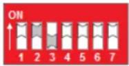 MAX + MIN MAX + MIN | * see note |
| 3 | + PEAK- PEAKMAX + MINTIR | - UP- UP- DOWN- DOWN | 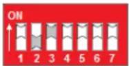 - PEAK - PEAK | 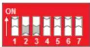 TIR TIR | * see note |
| 4 | LIVE display | PEAK Display | |||
| 5 | Front Panel TARE - normal operation | Front Panel TARE used for PEAK / RESET | |||
| 6 | Standard Run-Time Operation | Selects THRESHOLD display adjustment | |||
| 7 | 1% Full Scale Peak "Backout" Detect | 0.1% Full Scale Peak "Backout" Detect | |||
* Note: When in the Max-Min or TIR mode, the signal may over-range due to the sum of the +/- Peak captured signals being greater than full scale. Nominal capture level should be in the area of 50% full scale or less.
Functional Block Diagram of the PEAK switch settings
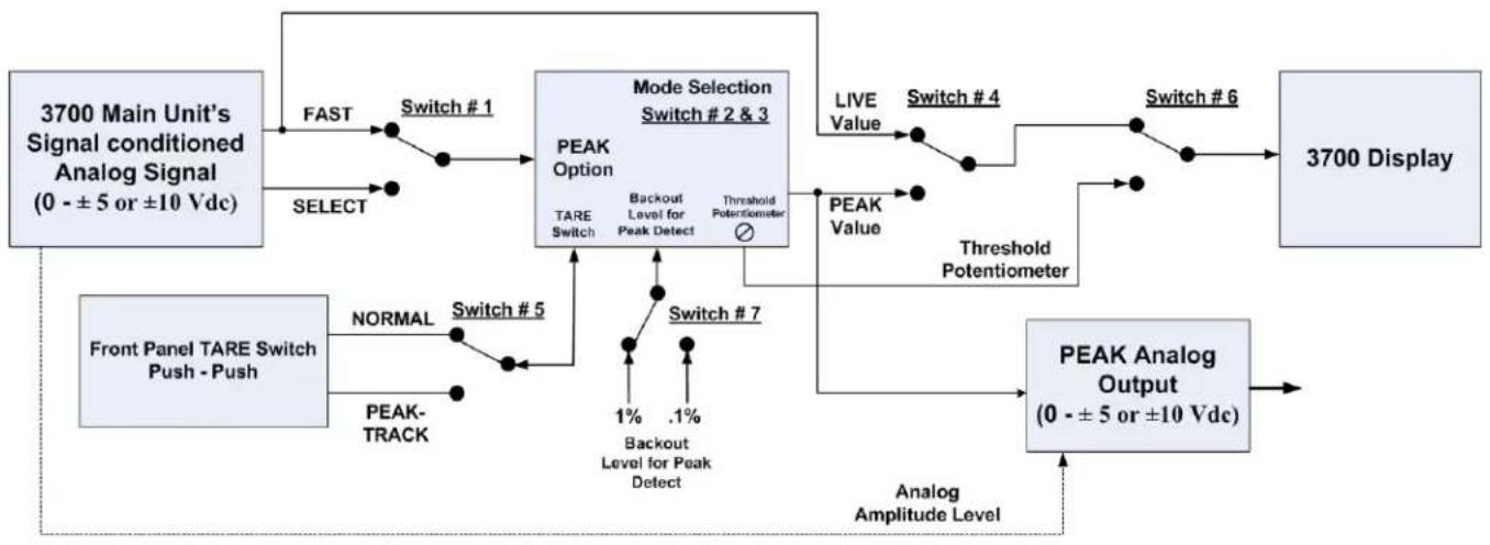
flowchart
graph TD
    A["3700 Main Unit's Signal conditioned Analog Signal (0 - ±5 or ±10 Vdc)"] --> B["FAST"]
    B --> C["Switch #1"]
    C --> D["MODE Selection Switch #2 & 3"]
    D --> E["PEAK Option"]
    E --> F["TARE Switch"]
    F --> G["BACKOUT Level for Peak Detect"]
    G --> H["Threshold Potentiometer"]
    H --> I["LIVE Value"]
    I --> J["Switch #4"]
    J --> K["Switch #6"]
    K --> L["3700 Display"]
    M["Front Panel TARE Switch Push - Push"] --> N["NORMAL"]
    N --> O["Switch #5"]
    O --> P["PEAK-TRACK"]
    P --> Q["Switch #7"]
    Q --> R["1% Backout Level for Peak Detect"]
    R --> S[".1%"]
    S --> T["Threshold Potentiometer"]
    T --> U["PEAK Value"]
    U --> V["NEAR"]
    V --> W["Analog Amplitude Level"]
    X["PEAK Analog Output (0 - ±5 or ±10 Vdc)"] --> Y["NEAR"]
3. PEAK Interface I/O Connections
Pin assignments for the 3700P board's 8-pin I/O connector (shown in Fig. 1) functional description
Pin Number
Function
| 1 | Output | HAVE PEAKOutput Logic Signal, indicates a Peak has been detected. |
| 2 | Input | TRACK or PEAKInput Logic Signal to Clear (Track) or to Arm for a Peak capture function |
| 3 | Input | TRACK or HOLDInput Logic Signal to HOLD the Peak reading. Must be in Track Mode to clear Peak (Pin 2 false, not grounded) |
| 4 | LOGIC COMMONCommon for Logic signal activation | |
| 5 | Input | DISPLAY - LIVE or PEAK ReadingInput Logic Signal to select Live Reading or Peak Reading for front panel display |
| 6 | Input | FRONT PANEL TARE for Display of PEAK or LIVE signalInput Logic Signal to use the front panel TARE switch for PEAK or LIVE display reading |
| 7 | ANALOG COMMONCommon for analog signal reference | |
| 8 | Output | PEAK ANALOG SIGNALAnalog Output - Holds PEAK analog value when in PEAK mode; follows analog input continuously when in TRACK mode. Full scale level is determined by the 3700 main units output selection - +/- 5V or +/- 10V. |
4. Setup conditions for the "P" option and TARE switch operation
When the "P" option is installed - the front panel "TARE" Push/Push switch can be configured to operate in three separate function modes for local operation depending on the DIP switch selection and/or logic inputs selected.
Function Mode of the TARE switch
- Standard "TARE" capability for normal operation - Will TARE the input measurement of the analog signal and the display to "Zero". LED will light GREEN when active and within normal offset TARE range. Remote TARE via the rear connector functions in a similar fashion.
- PEAK capture or Track mode - When the TARE switch is depressed, the meter will be in "track" mode following the input signal amplitude. When the TARE switch is released (outward position) the meter is armed and ready to capture the Peak as configured by Dip Switch 2 & 3.
- Used for local control of the Front Panel display -TARE button depressed will display the PEAK reading. Outward position of the switch will display the "Live" reading. Switch action will not perform a Peak reset operation, this must be done via connection terminal 2's activation for TRACK - PEAK.
Note: If the Peak option is installed in a Model 3740 Frequency conditioner, the TARE mode switch functionality is only accessible via the rear logic connector input
Function Mode Setup and configuration details
1. Standard TARE operation Default condition
- Dip Switch 4 & 5 UP, Peak Input connection Pin 5 and 6 are not used. Remote connections for remote TARE are available. Refer to the main meter manual for details.
2. Front Panel Peak Reset Function
- Dip Switch 4 & 5 DOWN or Switch 4 DOWN and Input connection Pin 5 Grounded (True). Input connection Pin 6 can not be used. Remote TARE function operates via main meter connector.
3. Local Display of Live or Peak Reading
- Dip Switch 4 & 5 UP, Input connection Pin 5 not utilized, Pin 6 is grounded (True). Remote TARE function operates via main meter connector.
4. Interface I/O Connections
Interface Connector Operation
The 8 pin rear connector provides remote access to the Peak operational parameters. All logic I/O are negative true signals - logic common when active or true.
Functional diagrams of the logic for enabling PEAK functions are shown in Fig. 3 thru 6. Typically usage of the I/O connections are for remote control of the application sequence to "handshake" with a controller for proper operation of the measurement capture and resetting process of the PEAK Mode function.
Display Source and Front Panel TARE button mode of operationl are available to provide remote control enabling of the local operation of the 3700 Peak features as configured by the 7 postion dip switch settings as described in section 2.
Analog Output of the PEAK Mode function is available. The Analog level is dependent on the configuration of the main analog controls of the 3700 unit... +/- 5 V or +/- 10 Vdc full scale level. Analog output, when in the HOLD or PEAK capture mode, is accomplished using capacitive memory and will have a "leak" rate of 1 millivolt per 10 seconds.
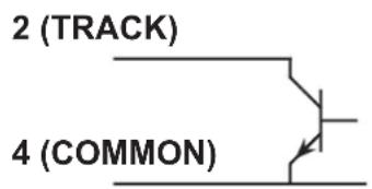
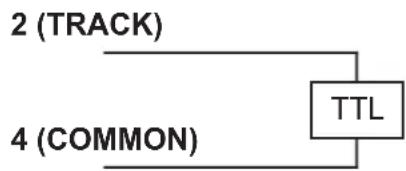
Fig. 2
Track/PEAK Via External Command (Switch, Open Collector Transistor, or TTL Logic)

flowchart
graph TD
    A["2 (TRACK)"] --> B["TTL"]
    C["4 (COMMON)"] --> B
    B --> D["End"]
+ PEAK Mode - captures and holds the most positive signal amplitude of the measurement within the positive quadrant of the signal. Switch 2 UP - Switch 3 UP
Fig 3

line
| Level | Input | Output (+ PEAK) | |-------|-------|-----------------| | Zero Level | - | - | | P1 | Peak | - | | P2 | Peak | + Peak | | Logic Inputs | - | - | | Logic Output | - | Have PEAK |- PEAK Mode - captures and holds the most negative signal amplitude of the measurement within the negative quadrant of the signal. Switch 2 DOWN - Switch 3 UP
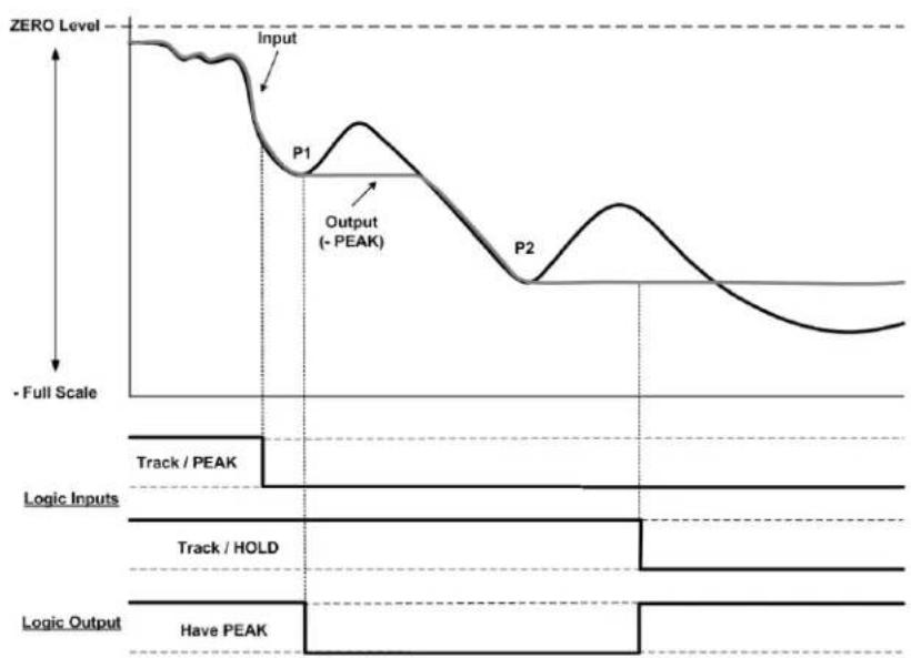
Fig 4
line
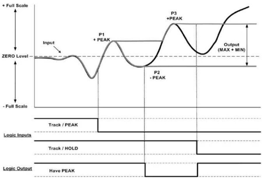
| Signal | Value | |-----------------|-------| | Input | Zero Level | | Output (-PEAK) | Peak | | P1 | Peak | | P2 | Peak | | Logic Inputs | Track / PEAK | | Logic Inputs | Track / HOLD | | Logic Output | Have PEAK |MAX + MIN Mode - captures and holds the most positive signal and the most negative signal amplitude in the positive and negative quadrants of the measurement resulting in an absolute analog output signal. Switch 2 UP - Switch 3 DOWN
Fig 5
line
| Phase | Value | |-------------|-------| | Input | Zero Level | | P1 | Peak | | P2 | Peak | | P3 | Peak | | Output | MAX + MIN |Note: When in Max-Min mode the analog signal may overrange due to the summing of the + Peak and - Peak captured signal.
TIR Mode - captures and holds the most positive signal and the most negative signal amplitude in the positive quadrant of the measurement. Switch 2 DOWN - Switch 3 DOWN
Fig 6
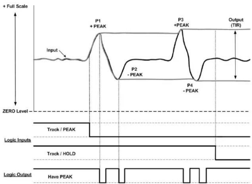
line
| Phase | Value | |-------------|--------| | Input | Peak | | P1 | + PEAK | | P2 | - PEAK | | P3 | + PEAK | | P4 | - PEAK | | Output (TIR)| TIR |Threshold Level Adjust and Have Peak Detection (Backout)
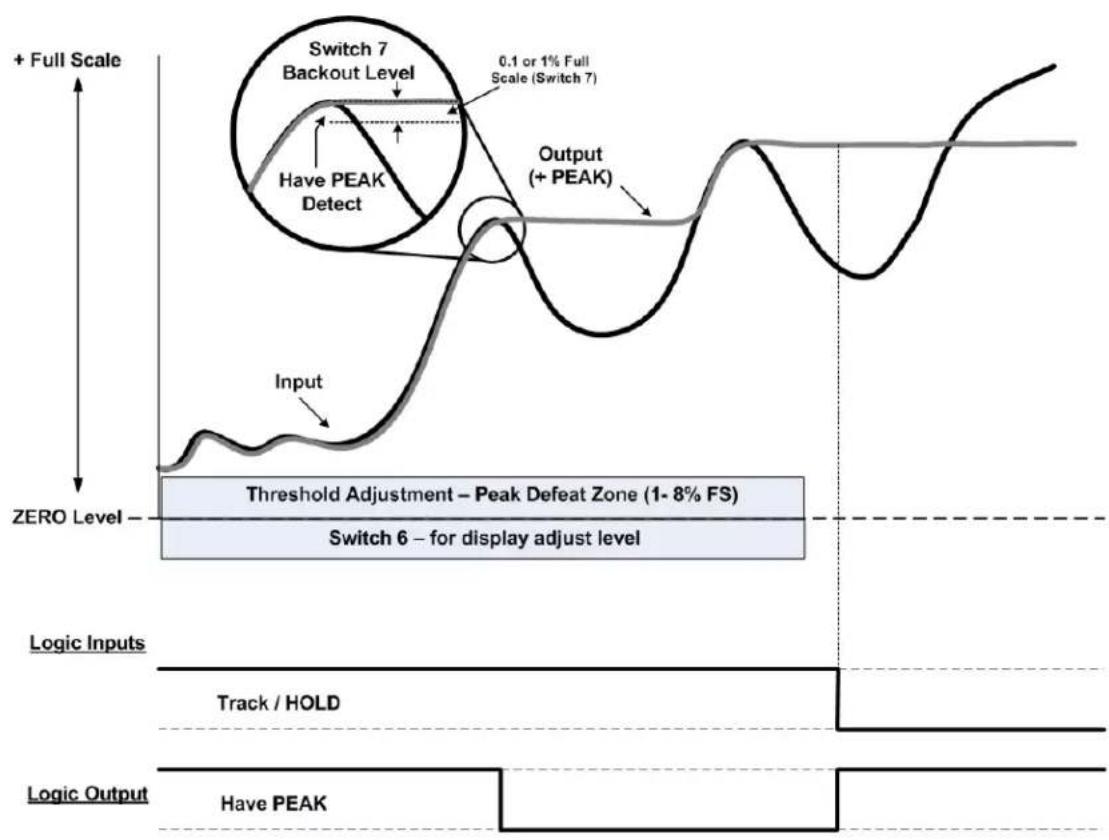
Switch 6 - PEAK THRESHOLD DISPLAY ADJUST on the rear panel dip switch: When in the DOWN position, will switch the front panel display to provide level adjustment of the Threshold Potentiometer to provide a "No Peak Zone" around the Zero level. This adjustment is used to eliminate false Peak Captures around the zero measurement level as shown in the gray area of the Fig. 7 below. Adjustment is from 1 to 8% of the full scale reading.
Switch 7 - HAVE PEAK DETECT (Backout): Selects the amplitude of the "delta" between the live signal and the detection of a Peak value which has occurred. Sometimes referred to as "Backout" as shown in the circle graphics below. This level sets the recognition level of when a PEAK has occurred. Level is 0.1% (DOWN) or 1.0% (UP) of full scale. Setting will depend on signal dynamic content and the sharpness of the peak event. Placement of Switch 1 (Analog Signal Source) will also have an affect on this setting due to the analog filtering response of the FAST or the SELECTED analog signal as determined by the response time of the FAST signal for the 3700 Model or the Select Analog Filter per the Analog Control switches located on the main 3700 unit.....switch 3 & 4.
Fig 7
flowchart
graph TD
    A["Input"] --> B["Threshold Adjustment – Peak Defeat Zone (1-8% FS)"]
    B --> C["Output (+ PEAK)"]
    D["+ Full Scale"] --> E["Switch 7 Backout Level"]
    E --> F["Have PEAK Detect"]
    F --> G["0.1 or 1% Full Scale (Switch 7)"]
    G --> H["Output"]
    I["ZERO Level"] --> J["Switch 6 for display adjust level"]
    K["Logic Inputs"] --> L["Track / HOLD"]
    M["Logic Output"] --> N["Have PEAK"]
    style A fill:#f9f,stroke:#333
    style B fill:#ccf,stroke:#333
    style C fill:#cfc,stroke:#333
    style D fill:#fcc,stroke:#333
    style E fill:#cff,stroke:#333
    style F fill:#ffc,stroke:#333
    style G fill:#fcf,stroke:#333
    style H fill:#cff,stroke:#333
    style I fill:#fff,stroke:#333
    style J fill:#fff,stroke:#333
    style K fill:#fff,stroke:#333
    style L fill:#fff,stroke:#333
    style M fill:#fff,stroke:#333
    style N fill:#fff,stroke:#333
Quick Set-up operation
1. Determine the Peak Mode required
Configure switch settings 2 and 3 for the proper function.
2. Select FAST or SELECT signal source
Configure switch 1 - FAST will be the highest dynamic capture. SELECT will reflect the low pass filter selection on the main 3700 Analog Controls.
3. Select the Front Panel Operation of the TARE Switch
Configure switch 5 - Normal operation of the TARE switch to provide "zero-ing" of the analog signal or to use the TARE switch as a front panel PEAK -TRACK "push-push" operation to place the 3700 unit is PEAK capture Mode or Reset the PEAK that has been held resulting in the display and analog output signal tracking the live input. Push IN - PEAK. Push OUT - TRACK.
4. Select the Operation of the Display
Switch 4 - Meter display can be configured for LIVE display or the PEAK capture value. If the unit is a "stand-alone" meter with the local operator providing the Peak Reset, as mentioned in step 3, then Switch 4 should be DOWN for PEAK display operation. Remote control of the display can also be done via the I/O connections with an external switch or controller providing the Display control function.
5. Determine how much "threshold" level is needed for your application
Switch 6 will display the threshold value (1 to 8%) for a bi-polar "no peak detection zone" around the Zero measurement level. This adjustment is normally in the 5% area, but can be adjusted depending on the application and how much PEAK defeat / rejection is needed. When finished with the potentiometer adjustment, return Switch 6 to the UP position.
6. Determine the need for remote control of your application
Refer to the Connector I/O interface in section 3 for setup functions of the 8 positon terminal connector. Switch function 4 and 5 can be remotely controlled. All other switch settings are typically configured during initial setup of the 3700 unit and will not be changed.
Peak Capture Response
The Peak Capture of the analog signal is performed using “capacitive” memory. This technique is very repeatable and does not involve digital sampling errors. It does, however, result in a millivolt/second “leak rate” after the initial “capture” which varies depending on the Peak Capture cycle rate, amplitude of the analog signal and the wave shape of the signal being monitored. Below are the leak rate values as expressed in percent of full scale using defined parameters of a single square wave pulse input of 1, 10 and 100 milliseconds in duration at the full scale value of 5.000 V.
Square Wave Full Scale Error after Peak was captured
| Pulse Width | 10 mS | 100 mS | 1 Sec | |
| 1 mS | 0.10% | 0.15% | 0.20% | |
| 10 mS | 0.05% | 0.07% | 0.10% | |
| 100 mS | 0.02% | 0.02% | 0.06% |
Typical Leak rate graph with a 100 mS pulse example
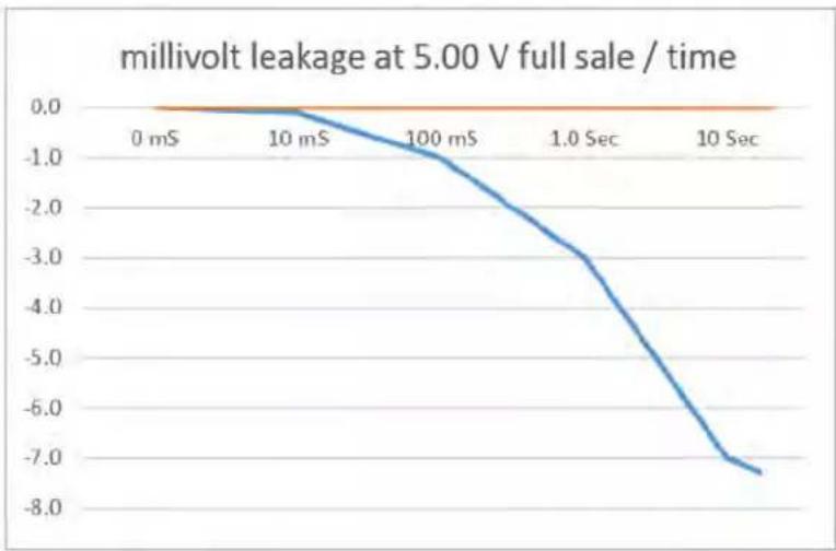
line
| Time | Millivolt Leakage | | -------- | ----------------- | | 0 mS | 0.0 | | 10 mS | -0.5 | | 100 mS | -1.5 | | 1.0 Sec | -3.0 | | 10 Sec | -7.5 |Page left blank
Copyright © 2015, Daytronic Corporation. All rights reserved.
No part of this document may be reprinted, reproduced, or used in any form or by any electronic, mechanical, or other means, including photocopying and recording, or in any information storage and retrieval system, without permission in writing from Daytronic Corporation. All specifications are subject to change without notice.

DAYTRONIC
Daytronic Corporation

- General Description
- DIP Switch Configuration
- Default Position - Switches are all "ON" (UP)
- Switch #
- Function
- PEAK Interface I/O Connections
- Setup conditions for the "P" option and TARE switch operation
- Function Mode of the TARE switch
- Function Mode Setup and configuration details
- Standard TARE operation Default condition
- Front Panel Peak Reset Function
- Local Display of Live or Peak Reading
- Interface I/O Connections
- Interface Connector Operation
- Threshold Level Adjust and Have Peak Detection (Backout)
- Quick Set-up operation
- Determine the Peak Mode required
- Select FAST or SELECT signal source
- Select the Front Panel Operation of the TARE Switch
- Select the Operation of the Display
- Determine how much "threshold" level is needed for your application
- Determine the need for remote control of your application
- Peak Capture Response
- Page left blank
- Copyright © 2015, Daytronic Corporation. All rights reserved.
- DAYTRONIC
Brand : Daytronic
Model : 3700P
Category : Meter