
RMK-6K - Signal Processing Daytronic - Free user manual and instructions
Find the device manual for free RMK-6K Daytronic in PDF.

| Product Type | Rackmount Kit for SPS6000 Signal Processing System |
| Compatible Models | SPS6108D-CE, SPS6116D-CE, SPS6132D-CE, and other SPS6000 mainframes |
| Rack Standard | 19-inch instrument rack |
| Panel Height | 5.22 inches (13.26 cm) |
| Rack Units (U) | Approximately 3U |
| Material | Metal (extruded aluminum mainframe compatible) |
| Installation Type | Panel-mount or rack-mount with included hardware |
| Included Hardware | Clamp slides, clamp screws (for panel mounting), rackmount brackets |
| Maximum Panel Thickness | 6 mm (0.24 in) |
| Weight (estimated) | Approximately 2 kg (4.4 lb) for the kit alone |
| Power Requirements (host) | 100-240 VAC, 47-63 Hz, 55 W max |
| Environmental Operating Temperature | +5°C to +50°C (+41°F to +122°F) |
| Environmental Humidity | 5% to 95% noncondensing |
| Safety Compliance | CE marked, EN 61010, EMC EN50082-1, EN55011 |
| Maintenance | Periodic cleaning of dust from air intake; keep fan unobstructed |
| Accessories Included | Rackmount ears, screws, mounting instructions |
| Warranty | Standard Daytronic warranty (typically 1 year) |
| Country of Origin | USA (Daytronic Corporation, Dayton, OH) |
Frequently Asked Questions - RMK-6K Daytronic
User questions about RMK-6K Daytronic
0 question about this device. Answer the ones you know or ask your own.
Ask a new question about this device
Download the instructions for your Signal Processing in PDF format for free! Find your manual RMK-6K - Daytronic and take your electronic device back in hand. On this page are published all the documents necessary for the use of your device. RMK-6K by Daytronic.
USER MANUAL RMK-6K Daytronic
Declaration of Conformity
Manufacturer's Name: Daytronic Corporation
Manufacturer's Address: 2211 Arbor Blvd., Dayton, OH USA 45439-1521
declares that the products
Product Name: SPS6000 Signal Processing System
Product Models: SPS6108-CE SPS6116-CE SPS6132-CE
SPS6108D-CE SPS6116D-CE SPS6132D-CE
provided that
- They are used only with ASP connector assemblies bearing the model number SPS6056-CE.
- They are used only with signal conditioner connector assemblies bearing model numbers with the -CE suffix in compliance with instructions contained within the SPS6000 user manual part number 91937.00, version SB.3.2.0 or higher.
- That all connections to the system are made in compliance with instructions contained within the SPS6000 user manual part number 91937.00, version SB.3.2.0 or higher.
then conform to the following specifications:
Safety: EN 61010 : 1993
EMC: IEC801-2: 1984 EN50082-1 : 1992 8 kV AD, 4 kV CD, Criterion B
IEC801-3: 1984 EN50082-1 : 1992 3 V/m, 27-500 MHz, Criterion A
IEC801-4: 1988 EN50082-1 : 1992 0.5 kV Signal Lines, 1 kV Power Lines, Criterion B
EN55011: 1998 Group 1, Class A
Supplementary Information:
These products herewith comply with the requirements of the Low Voltage Directive 73/23/EEC and the EMC Directive 89/336/EEC as amended by Directive 93/68/EEC.
Dale Lankford, Principal Engineer June 1, 1990 Wayne Holbrook, V.P. Engineering June 1, 1990 Bill Hedges, President June 1, 1999 Bill Hedges
Copyright © 1998, 1999, Daytronic Corporation. All rights reserved.
No part of this document may be reprinted, reproduced, or used in any form or by any electronic, mechanical, or other means, including photocopying and recording, or in any information storage and retrieval system, without permission in writing from Daytronic Corporation. All specifications are subject to change without notice.
SPS6000 is a trademark of Daytronic Corporation.
SPS6000
SIGNAL PROCESSING SYSTEM
INSTRUCTION MANUAL
Daytronic Corporation
1 INTRODUCTION
a. General Description of the SPS6000 System 1-1
b. Summary of Key SPS6000 Features 1-3
c. System Hardware Components
-
Mainframe
a. General Description 1-5
b. Physical Specifications 1-7
c. Panel Mounting 1-7
d. Front-Panel Display and Operator Keypad 1-8
e. Diagnostic Output 1-9 -
Signal Conditioner Cards 1-10
-
Analog Signal Processor (ASP) Card(s) 1-11
-
Analog Function Modules 1-13
d. System Software
- SPS6000 Configurator Software 1-14
e. Overview of SPS6000 Signal Pathing
- Defining ASP Input Channels 1-15
- Defining ASP Output Channels 1-16
- What Tag Names Really Name 1-18
- Defining ASP Signal Paths 1-20
- The ASP Worksheet 1-22
2 GETTING STARTED
a. Introduction: Overview of System Setup 2-1
b. Hardware Installation
- Card Insertion and Removal 2-2
- Mounting of ASP Function Modules 2-5
- Analog Input (Transducer) Connections and Setup 2-6
- ASP External Logic I/O Connections 2-10
- Connection of Setup Computer 2-15
- Host Data Connections (PC, PLC) 2-15
- Connection of Diagnostic Output 2-15
- Connection of Optional Remote Display/Keypad Unit(s) 2-17
- SPS6000 Power Connections 2-17
c. Software Installation and Deinstallation
- Installing SPS6000 Configurator Software 2-18
- Uninstalling SPS6000 Configurator Software 2-18
d. Powering Up the SPS6000 2-19
3 CONFIGURATION
a. Introduction ...... 3-1
- Running and Quitting the Configurator Program 3-1
- A Quick Look at Menus, Tools, and Help 3-2
a. The "File" Menu 3-3
b. The "Hardware Setup" Menu 3-5
c. The "System Configuration" Menu 3-5
d. The "View" Menu 3-6
e. The "Help" Menu 3-6
f. Toolbar Commands 3-6
g. Getting On-Line Help 3-7
- Creating and Downloading a New Configuration
a. Using Tag Names to Define Signal Paths 3-8
b. The Overall Procedure 3-10
-
Standard Operations via Mouse or Keyboard 3-14
-
Port Setup 3-16
b. Tutorial: Creating, Validating, and Saving New Configurations ...... 3-17
c. Configuration Management
- Opening an Existing Configuration 3-46
- Saving the Open Configuration 3-47
- Saving the Open Configuration as Another Configuration .... 3-47
- Downloading the Open Configuration to the Connected SPS6000 System 3-48
- Uploading the Working Configuration of the Connected SPS6000 System 3-49
- Printing Configuration Reports a. Selecting Report Sections .... 3-50 b. Printing the Report .... 3-51
d. On-Line Selection of Analog Filtering
e. On-Line Calibration of Input Channels
- Display/Keypad vs. Software "On-Line" Calibration Window 3-54
- Displaying Active Channels 3-56
- Displaying Output Voltages 3-57
- Saving or Cancelling On-Line Changes 3-57
- Calibration: Calculated vs. On-Line 3-58
- Two-Point (Deadweight) Calibration 3-59
- Simulated (Shunt) Calibration of Strain Gage Channels 3-61
f. Security Settings for Display/Keypad 3-63
APPENDIX A CONNECTION AND SETUP OF ANALOG
INPUT CARDS AND ACCESSORIES ...... A-1
Model 10A18-4C Quad 100-Ohm Platinum Linear RTD Conditioner Card
- General Description and Specifications 10A18-4C.1
- Transducer Connections 10A18-4C.3
- Setup and/or Operating Considerations
a. Setting a 10A18-4C Channel for Four-Wire or Three-Wire RTD Cabling .... 10A18-4C.5
b. Configuration and Calibration 10A18-4C.6
Calculated Calibration 10A18-4C.6
Two-Point (Deadweight) Calibration 10A18-4C.7
Model 10A30-2C Dual LVDT Conditioner Card
- General Description and Specifications 10A30-2C.1
- Transducer Connections 10A30-2C.2
- Setup and/or Operating Considerations
a. Configuration and Calibration 10A30-2C.7
Calculated Calibration 10A30-2C.7
Two-Point (Deadweight) Calibration 10A30-2C.8
Model 10A31-4 Quad LVDT Conditioner Card
- General Description and Specifications 10A31-4.1
- Transducer Connections 10A31-4.2
- Setup and/or Operating Considerations
a. Configuration and Calibration 10A31-4.8
Calculated Calibration 10A31-4.8
Two-Point (Deadweight) Calibration 10A31-4.9
Model 10A41-2C Dual Frequency Input Conditioner Card
- General Description and Specifications 10A41-2C.1
- Transducer Connections
a. Standard Cabling 10A41-2C.2
b. Special Cabling
Ungrounded Frequency Source 10A41-2C.4
Elimination of DC Offset 10A41-2C.6
Suppression of High-Frequency Noise in
Low-Frequency Input 10A41-2C.6
c. Pull-Up Resistor 10A41-2C.6
- Setup and/or Operating Considerations
a. Selecting Input Voltage Range 10A41-2C.7
b. Selecting Filter Bandwidth 10A41-2C.8
c. Configuration and Calibration 10A41-2C.9
Calculated Calibration 10A41-2C.9
Two-Point (Deadweight) Calibration 10A41-2C.10
Model 10A60-4 Quad Voltage Conditioner Card
- General Description and Specifications 10A60-4.1
- Transducer Connections 10A60-4.2
- Setup and/or Operating Considerations
a. Configuration and Calibration 10A60-4.5
Calculated Calibration 10A60-4.5
Two-Point (Deadweight) Calibration 10A60-4.6
Model 10A61-2 Dual 4-20 mA Conditioner Card
- General Description and Specifications 10A61-2.1
- Transducer Connections 10A61-2.2
- Setup and/or Operating Considerations
a. Configuration and Calibration 10A61-2.3
Calculated Calibration 10A61-2.3
Two-Point (Deadweight) Calibration 10A61-2.4
Model 10A63-2 Dual Voltage Conditioner Card
- General Description and Specifications 10A63-2.1
- Transducer Connections 10A63-2.2
- Setup and/or Operating Considerations
a. Configuration and Calibration 10A63-2.6
Calculated Calibration 10A63-2.6
Two-Point (Deadweight) Calibration 10A63-2.7
Model 10A68-2 Dual AC RMS Conditioner Card
- General Description and Specifications 10A68-2.1
- Transducer Connections 10A68-2.2
- Setup and/or Operating Considerations
a. Configuration and Calibration 10A68-2.3
Calculated Calibration 10A68-2.3
Two-Point (Deadweight) Calibration 10A68-2.4
Model 10A70-2 Dual Strain Gage Conditioner Card
- General Description and Specifications 10A70-2.1
- Transducer Connections 10A70-2.2
- Setup and/or Operating Considerations
a. Configuration and Calibration 10A70-2.5
Calculated Calibration 10A70-2.5
Two-Point (Deadweight) Calibration 10A70-2.6
Model 10A72-2C Enhanced Dual Strain Gage Conditioner Card
- General Description and Specifications 10A72-2C.1
- Transducer Connections 10A72-2C.3
- Setup and/or Operating Considerations
a. Selection of Conditioner Modes 10A72-2C.6
b. Selection of Excitation Levels 10A72-2C.7
c. Selection of Analog Filters 10A72-2C.7
d. Configuration and Calibration 10A72-2C.7
Calculated Calibration 10A72-2C.7
Two-Point (Deadweight) Calibration 10A72-2C.8
Simulated (Shunt) Calibration 10A72-2C.9
- Optional Bridge Completion: Model 10CJB-2 Dual Bridge Completion Card
a. Purpose 10A72-2C.11
b. 10CJB-2 Transducer Connections ...... 10A72-2C.12
c. Calibration
Calculated Calibration 10A72-2C.13
Two-Point (Deadweight) Calibration 10A72-2C.13
Simulated (Shunt) Calibration 10A72-2C.13
Coarse Zero Offset 10A72-2C.14
Model 10A73-4 1/2 & 1/4 Bridge Strain Gage Conditioner Card
- General Description and Specifications 10A73-4.1
- Gage / Transducer Connections 10A73-4.3
a. 1/4-, 1/2-, or Full-Bridge Gage Connections
Using a Daytronic Bridge Completion Connector .... 10A73-4.4
b. 1/4-, 1/2-, or Full-Bridge Gage Connections
Using the Model 10CJB-4 .... 10A73-4.8
c. Full-Bridge Transducer Connections
(Without Bridge Completion) 10A73-4.9
- Setup and/or Operating Considerations
a. Selection of Excitation Level 10A73-4.10
b. Configuration and Calibration .... 10A73-4.11
Calculated Calibration .... 10A73-4.12
Two-Point (Deadweight) Calibration 10A73-4.13
Simulated (Shunt) Calibration 10A73-4.13
c. Setting an Initial Zero Offset with the Model 10CJB-4 ...... 10A73-4.16
Model 10A78 AC Strain Gage Conditioner Card
- General Description and Specifications 10A78.1
-
Transducer Connections 10A78.2
-
Setup and/or Operating Considerations
a. Phase and Symmetry Adjustment for All Transducers Except a Lebow 1800 Series Transducer .... 10A78.6
b. Phase and Symmetry Adjustment for a Lebow 1800 Series Transducer .... 10A78.7
c. Configuration and Calibration ..... 10A78.8
Calculated Calibration ..... 10A78.8
Two-Point (Deadweight) Calibration ..... 10A78.9
Simulated (Shunt) Calibration ..... 10A78.10
Model 10A96 Amplified Accelerometer Vibration Conditioner Card
- General Description and Specifications 10A96.1
- Transducer Connections 10A96.2
- Setup and/or Operating Considerations
a. Setting Front-End Amplifier Gain 10A96.5
b. Setting High-Pass Filter Gain 10A96.5
c. Setting Band-Pass Filter Cutoff Frequency 10A96.5
d. Configuration and Calibration .... 10A96.6 Calculated Calibration .... 10A96.6
Model AA14-4F010 Thermocouple Conditioner Card
- General Description and Specifications .... AA14-4F010.1
- Transducer Connections ...... AA14-4F010.3
- Setup and/or Operating Considerations
a. Selection of "Open TC" Polarity ...... AA14-4F010.6
b. Selection of Analog Output Modes ...... AA14-4F010.7
c. Configuration and Calibration .... AA14-4F010.7 Calculated Calibration .... AA14-4F010.7 Two-Point (Deadweight) Calibration .... AA14-4F010.8 - Diagnostic Wire-Wrap Pins ...... AA14-4F010.9
Model AA30-4 LVDT Conditioner Card
- General Description and Specifications .... AA30-4.1
- Connections
a. Transducer Connections ...... AA30-4.4
b. Connection of External Excitation Source ...... AA30-4.7 - Setup and/or Operating Considerations
a. Selection of Excitation Source ...... AA30-4.8
b. Selection of Analog Filtering Via Hardware Switches ....... AA30-4.8 Via Configurator Software or "Filter" Button ....... AA30-4.9
c. Selection of Analog Output Modes ...... AA30-4.10
d. Configuration and Calibration .... AA30-4.10 Calculated Calibration .... AA30-4.10 Two-Point (Deadweight) Calibration .... AA30-4.11 - Diagnostic Wire-Wrap Pins .... AA30-4.12
Model AA41-2 / AA41-4 Frequency Input Conditioner Card
- General Description and Specifications .... AA41-2/4.1
- Transducer Connections
a. Standard Cabling ...... AA41-2/4.4
b. Special Cabling Ungrounded Frequency Source .... AA41-2/4.4 Elimination of DC Offset .... AA41-2/4.5 Suppression of High-Frequency Noise in Low-Frequency Input .... AA41-2/4.7
c. Pull-Up Resistor ...... AA41-2/4.7
3. Setup and/or Operating Considerations
a. Selection of Input Voltage Range ...... AA41-2/4.7
b. Selection of Analog Filtering Via Hardware Switches .... AA41-2/4.7 Via Configurator Software or "Filter" Button .... AA41-2/4.9
c. Configuration and Calibration .... AA41-2/4.9 Calculated Calibration .... AA41-2/4.9 Two-Point (Deadweight) Calibration .... AA41-2/4.11
- Diagnostic Wire-Wrap Pins ...... AA41-2/4.12
Model AA72-2 / AA72-4 Strain Gage Conditioner Card
-
General Description and Specifications ...... AA72-2/4.1
-
Transducer Connections ...... AA72-2/4.5
-
Setup and/or Operating Considerations
a. Selection of Excitation Levels ...... AA72-2/4.7
b. Selection of Analog Filtering Via Hardware Switches .... AA72-2/4.8 Via Configurator Software or "Filter" Button .... AA72-2/4.9
c. Selection of Analog Output Modes ...... AA72-2/4.10
d. Configuration and Calibration .... AA72-2/4.10 Calculated Calibration .... AA72-2/4.11 Two-Point (Deadweight) Calibration .... AA72-2/4.12 Simulated (Shunt) Calibration .... AA72-2/4.12
- Optional Bridge Completion: Model 10CJB-2 Dual Bridge Completion Card
a. Purpose ...... AA72-2/4.14
b. 10CJB-2 Transducer Connections ...... AA72-2/4.15
c. Calibration Calculated Calibration .... AA72-2/4.15 Two-Point (Deadweight) Calibration .... AA72-2/4.16 Simulated (Shunt) Calibration .... AA72-2/4.16 Coarse Zero Offset .... AA72-2/4.16
- Diagnostic Wire-Wrap Pins ...... AA72-2/4.17
APPENDIX B SPS6000 FUNCTION MODULES
Concerning Function Module Logic I/O Signals B-1
-
Model SPS6701 Sum/Difference Module B-1
-
Model SPS6702 Peak and Track/Hold Module B-2
a. "Track and Hold" Operation B-3
b. "Peak Capture and Hold" Operation B-3
c. "Sample and Hold" Operation B-7
-
Model SPS6703 Auto Zero Module B-8
-
Model SPS6704 Comparator Module B-10
a. "HI-LO" Mode B-10
b. "Dual" Mode B-11
c. "Window" Mode B-12
APPENDIX C SPS6000 ON-LINE COMMANDS
- Command Summary ...... C-1
- Standard Command Arguments ...... C-2
- Using Hyperterminal to Issue Commands C-3
- Command Descriptions ...... C-4
Illustrations
1.1 A General SPS6000 System 1-1
1.2 SPS6000 Signal Pathing 1-2
1.3 SPS6000 Mainframe Front Elements 1-5
1.4 SPS6000 Mainframe Rear Elements 1-6
1.5 Mainframe Dimensions 1-7
1.6 SPS6000 Panel Mounting 1-8
1.7 Front-Panel Operator Display and Keypad 1-9
1.8 Generalized ASP Input Channel "Block" 1-16
1.9 Generalized ASP Output Channel "Block" 1-17
1.10 ASP Signal Paths
1.10(a) ASP Signal Paths "Owned" by an ASP ANALOG INPUT 1-18
1.10(b) ASP Signal Paths "Owned" by a FUNCTION MODULE ANALOG OUTPUT .... 1-18
1.10(c) ASP Signal Paths "Owned" by an ASP LOGIC (CONTROL) INPUT ..... 1-19
1.10(d) ASP Signal Paths "Owned" by a FUNCTION MODULE LOGIC OUTPUT.... 1-19
1.11 Function Module Block Diagram for Force/Displacement Application ... 1-21
1.12 Worksheet Example No. 1 1-24
1.13 Worksheet Example No. 2 1-25
1.14 Worksheet Example No. 3 1-26
2.1 SPS6000 Slot Connection 2-2
2.2 Grouped Card Insertion
2.2(a) Insertion of ASP Cards (Empty Slot No. 8) 2-3
2.2(b) Insertion of ASP Cards with Slot No. 8 Card 2-4
2.3 ASP Card Function Module Sockets 2-5
2.4 "CONVENTIONAL" Daytronic Conditioner Connectors
2.4(a) Standard "10A" CONDITIONER CONNECTOR (No. 60322) 2-7
2.4(b) Typical "AA" CONDITIONER CONNECTOR 2-7
2.5 ASP I/O Connectors
2.5(a) "CONVENTIONAL" ASP Connector (Model SPS6046) 2-11
2.5(b) CE-COMPLIANT ASP Connector (Model SPS6056-CE) 2-12
2.6 Typical ASP Logic Connections 2-13
2.7 RS-232 Cabling to Setup Computer
2.7(a) To a 25-Pin PC Serial Port 2-14
2.7(b) To a 9-Pin PC Serial Port 2-14
2.8 Diagnostic Output Connections 2-16
2.9 Display Jumper and Connection 2-16
3.1 ASP1 Configuration Window for a New Configuration 3-2
3.2 Port Setup Window 3-16
3.3 System Configuration Window 3-17
3.4 Advanced Configuration Window 3-18
3.5 Card Slot Assignments Window 3-18
3.6 Function Module Assignments Window (ASP1) 3-20
3.7 Tutorial Worksheet No. 1 3-21
3.8 Analog Inputs Window 3-22
3.9 Analog Outputs Window 3-23
3.10 Input Configuration Window (Channel No. 34) 3-24
3.11 Tutorial Worksheet No. 2 3-29
3.12 SPS6702 Configuration Window 3-30
3.13 Function Module Outputs Window 3-32
3.14 Control I/O Window 3-32
3.15 Configuration Errors Window 3-34
3.16 Tutorial Worksheet No. 3 3-35
3.17 ASP1 Function Module Assignments for Step 76 3-37
3.18 ASP1 Analog Input Tag Names and Descriptions for Step 79 3-37
3.19 ASP1 Analog Output Tag Names for Step 85 3-38
3.20 SPS6702 I/O Tag Names for Step 87 3-39
3.21 SPS6704 I/O Tag Names for Step 92 3-40
3.22 SPS6704 I/O Tag Names for Step 96 3-41
3.23 SPS6702 I/O Tag Names for Step 98 3-42
3.24 SPS6702 I/O Tag Names for Step 101 3-42
3.25 ASP1 Function Module Output Tag Names and Descriptions for Step 104 3-43
3.26 ASP1 Control I/O Tag Names and Descriptions for Step 107 3-44
3.27 ASP1 Internal Control Names and Descriptions for Step 109 3-44
3.28 Standard "Open" Window 3-46
3.29 Standard "Save As" Window 3-47
3.30 Reports Window 3-51
3.31 On-Line Calibration Window 3-54
3.32 Data Entry Window 3-61
3.33 Display Window (for Display 1) 3-63
Appendix A: Model 10A18-4C
1 Range-Dependent Accuracy of the Model 10A18-4C
1(a) For DIN Standard Platinum RTD's (α = 0.00385) 10A18-4C.2
1(b) For American Standard Platinum RTD's (α = 0.00392) 10A18-4C.2
2 Model 10A18-4C "CONVENTIONAL" Transducer Cabling
2(a) Four-Wire RTD Cabling 10A18-4C.3
2(b) Three-Wire RTD Cabling 10A18-4C.4
3 Model 10A18-4C 4-Wire CE-COMPLIANT Transducer Cabling .. 10A18-4C.5
4 10A18-4C "RTD CABLING" Programming Jumper Pins .... 10A18-4C.5
Appendix A: Model 10A30-2C
1 Model 10A30-2C "CONVENTIONAL" Transducer Cabling
1(a) 5-Wire LVDT Cabling (under 20 ft. in length) 10A30-2C.3
1(b) 7-Wire LVDT Cabling (20 ft. or longer) 10A30-2C.3
1(c) 3-Wire Variable Reluctance Transducer Cabling (under 20 ft. in length) 10A30-2C.4
1(d) 5-Wire Variable Reluctance Transducer Cabling (20 ft. or longer) 10A30-2C.4
2 Model 10A30-2C CE-COMPLIANT Transducer Cabling
2(a) 5-Wire LVDT Cabling (under 20 ft. in length) 10A30-2C.5
2(b) 7-Wire LVDT Cabling (20 ft. or longer) 10A30-2C.5
2(c) 3-Wire Variable Reluctance Transducer Cabling (under 20 ft. in length) 10A30-2C.5
2(d) 5-Wire Variable Reluctance Transducer Cabling (20 ft. or longer) 10A30-2C.6
3 Long-Stroke LVDT Connections ("CONVENTIONAL" Cabling) ... 10A30-2C.6
4 Long-Stroke LVDT Connections (CE-COMPLIANT Cabling) ..... 10A30-2C.6
5 Jumpering of an Unused 10A30-2C LVDT Input ("CONVENTIONAL" or CE-COMPLIANT Cabling) .... 10A30-2C.6
Appendix A: Model 10A31-4
1 Model 10A31-4 Transducer Cabling
1(a) 5-Wire LVDT Cabling (under 20 ft. in length) 10A31-4.4
1(b) 7-Wire LVDT Cabling (20 ft. or longer) 10A31-4.5
1(c) 3-Wire Variable Reluctance Transducer Cabling (under 20 ft. in length) 10A31-4.6
1(d) 5-Wire Variable Reluctance Transducer Cabling (20 ft. or longer) 10A31-4.7
Appendix A: Model 10A41-2C
1 Model 10A41-2C "CONVENTIONAL" Transducer Cabling
1(a) Cabling to Grounded Frequency Sources 10A41-2C.3
1(b) Cabling to Ungrounded Frequency Sources 10A41-2C.3
1(c) Cabling to Zero-Velocity Sensors 10A41-2C.4
2 Model 10A41-2C CE-COMPLIANT Transducer Cabling
2(a) Cabling to Grounded Frequency Sources 10A41-2C.5
2(b) Cabling to Ungrounded Frequency Sources 10A41-2C.5
2(c) Cabling to Zero-Velocity Sensors 10A41-2C.5
3 Special 10A41-2C I/O Connections ("CONVENTIONAL" Cabling) .... 10A41-2C.6
4 Special 10A41-2C I/O Connections (CE-COMPLIANT Cabling) .. 10A41-2C.7
5 Model 10A41-2C Input Voltage Jumper Pins 10A41-2C.7
6 Model 10A41-2C Filter Bandwidth Jumper Pins 10A41-2C.8
Appendix A: Model 10A60-4
1 Model 10A60-4 "CONVENTIONAL" Transducer Cabling
1(a) 2-Wire Differential (Floating) Voltage Input 10A60-4.3
1(b) 2-Wire Single-Ended (Grounded) Voltage Input 10A60-4.3
2 Model 10A60-4 CE-COMPLIANT Transducer Cabling
2(a) 2-Wire Differential (Floating) Voltage Input 10A60-4.4
2(b) 2-Wire Single-Ended (Grounded) Voltage Input 10A60-4.4
Appendix A: Model 10A61-2
1 Model 10A61-2 "CONVENTIONAL" Transducer Cabling .... 10A61-2.2
2 Model 10A61-2 CE-COMPLIANT Transducer Cabling 10A61-2.3
Appendix A: Model 10A63-2
1 Model 10A63-2 "CONVENTIONAL" Transducer Cabling
1(a) 2-Wire Cabling: No Excitation from 10A63-2 10A63-2.3
1(b) 3-Wire Cabling: External Potentiometer, Zero to Full Scale ..... 10A63-2.3
1(c) 3-Wire Cabling: External Potentiometer, Zero Center .... 10A63-2.3
1(d) 4-Wire Cabling: DC-to-DC LVDT Input 10A63-2.4
2 Model 10A63-2 CE-COMPLIANT Transducer Cabling
2(a) 2-Wire Cabling: No Excitation from 10A63-2 10A63-2.4
2(b) 3-Wire Cabling: External Potentiometer, Zero to Full Scale ..... 10A63-2.5
2(c) 3-Wire Cabling: External Potentiometer, Zero Center 10A63-2.5
2(d) 4-Wire Cabling: DC-to-DC LVDT Input 10A63-2.5
Appendix A: Model 10A68-2
1 Model 10A68-2 Transducer Cabling 10A68-2.3
Appendix A: Model 10A70-2
1 Model 10A70-2 "CONVENTIONAL" Transducer Cabling
1(a) 4-Wire Strain Gage Cabling (under 20 ft. in length) 10A70-2.3
1(b) 6-Wire Strain Gage Cabling (20 ft. or longer) 10A70-2.3
2 Model 10A70-2 CE-COMPLIANT Transducer Cabling
2(a) 4-Wire Strain Gage Cabling (under 20 ft. in length) 10A70-2.4
2(b) 6-Wire Strain Gage Cabling (20 ft. or longer) 10A70-2.4
3 Jumpering of an Unused 10A70-2 Strain Gage Input ("CONVENTIONAL" or CE-COMPLIANT Cabling) 10A70-2.4
Appendix A: Model 10A72-2C
1 Model 10A72-2C "CONVENTIONAL" Transducer Cabling
1(a) 4-Wire Strain Gage Cabling (under 20 ft. in length) 10A72-2C.4
1(b) 8-Wire Strain Gage Cabling (20 ft. or longer) 10A72-2C.4
2 Model 10A72-2C CE-COMPLIANT Transducer Cabling
2(a) 4-Wire Strain Gage Cabling (under 20 ft. in length) 10A72-2C.5
2(b) 8-Wire Strain Gage Cabling (20 ft. or longer) 10A72-2C.5
3 Jumpering of an Unused 10A72-2C Strain Gage Input ("CONVENTIONAL" or CE-COMPLIANT Cabling) 10A72-2C.6
4 Model 10A72-2C Programming Jumper Pins .... 10A72-2C.6
5 Model 10A72-2C Shunt Calibration Resistors 10A72-2C.9
6 Logic Inputs for 10A72-2C Remote Shunt Calibration ("CONVENTIONAL" Cabling)
6(a) Switch Closure, No External Supply 10A72-2C.10
6(b) Active TTL Logic 10A72-2C.10
7 Logic Inputs for 10A72-2C Remote Shunt Calibration (CE-COMPLIANT Cabling)
7(a) Switch Closure, No External Supply 10A72-2C.11
7(b) Active TTL Logic 10A72-2C.11
8 Model 10CJB-2 Transducer Cabling 8(a) 2-Wire 1/4-Bridge Completion .... 10A72-2C.12
8(b) 3-Wire 1/4-Bridge Completion 10A72-2C.12
8(c) 1/2-Bridge Completion 10A72-2C.12
8(d) Full-Bridge Connection 10A72-2C.12
Appendix A: Model 10A73-4
1 Jumpering of an Unused 10A73-4 Strain Gage Input ("CONVENTIONAL" or CE-COMPLIANT Cabling) 10A73-4.3
2 Model 10A73-4 Strain Gage Cabling Using "CONVENTIONAL" Daytronic Bridge Completion Connectors
2(a) Per-Channel Connections to Model 10QBC-4 for 2-Wire 1/4-Bridge Completion 10A73-4.5
2(b) Per-Channel Connections to Model 10QBC-4 for 3-Wire 1/4-Bridge Completion .... 10A73-4.5
2(c) Per-Channel Connections to Model 10HBC-4 for 4-Wire 1/2-Bridge Completion .... 10A73-4.5
2(d) Per-Channel Connections to Model 10HBC-4 for 6-Wire 1/2-Bridge Completion 10A73-4.6
2(e) Per-Channel Connections to Model 10FBC-4 for Full-Bridge Connection .... 10A73-4.6
3 Model 10A73-4 Strain Gage Cabling Using CE-COMPLIANT Daytronic Bridge Completion Connectors
3(a) Per-Channel Connections to Model CQBC-CE for 2-Wire 1/4-Bridge Completion 10A73-4.6
3(b) Per-Channel Connections to Model CQBC-CE for 3-Wire 1/4-Bridge Completion 10A73-4.7
3(c) Per-Channel Connections to Model CUBC-CE for 4-Wire 1/2-Bridge Completion 10A73-4.7
3(d) Per-Channel Connections to Model CUBC-CE for Full-Bridge Connection 10A73-4.7
4 Model 10CJB-4 Transducer Cabling
4(a) 2-Wire 1/4-Bridge Completion 10A73-4.8
4(b) 3-Wire 1/4-Bridge Completion 10A73-4.8
4(c) 1/2-Bridge Completion 10A73-4.8
4(d) Full-Bridge Connection 10A73-4.8
5 10A73-4 Cabling to Four Full-Bridge Transducers 10A73-4.10
6 Model 10A73-4 Excitation Selection Via the TRACK Terminal of a CE-COMPLIANT Bridge Completion Connector .... 10A73-4.10
7 Model 10CJB-4 Offset Jumpers and Excitation Selection Switch 10A73-4.11
8 Model 10A73-4 Excitation Selection Without Bridge Completion 10A73-4.11
9 Model 10A73-4 Shunt Calibration Resistors 10A73-4.14
10 Logic Inputs for 10A73-4 Remote Shunt Calibration (Without Bridge Completion)
10(a) Switch Closure, No External Supply 10A73-4.15
10(b) Active TTL Logic 10A73-4.15
11 Logic Inputs for 10A73-4 Remote Shunt Calibration (Via CE-COMPLIANT Bridge Completion Connector)
11(a) Switch Closure, No External Supply 10A73-4.15
11(b) Active TTL Logic 10A73-4.15
Appendix A: Model 10A78
1 Model 10A78 "CONVENTIONAL" Transducer Cabling
1(a) 4-Wire Strain Gage Cabling (under 20 ft. in length) 10A78.3
1(b) 8-Wire Strain Gage Cabling (20 ft. or longer) 10A78.3
1(c) 8-Wire Cabling to Lebow 1600 Series Transducer (ONLY) ..... 10A78.4
2 Model 10A78 CE-COMPLIANT Transducer Cabling
2(a) 4-Wire Strain Gage Cabling (under 20 ft. in length) 10A78.5
2(b) 8-Wire Strain Gage Cabling (20 ft. or longer) 10A78.5
2(c) 8-Wire Cabling to Lebow 1600 Series Transducer (ONLY) ..... 10A78.5
3 10A78 Signal Programming Jumper Pads and Shunt Calibration Resistor .... 10A78.6
4 10A78 Phase and Symmetry Controls .... 10A78.6
Appendix A: Model 10A96
1 Model 10A96 "CONVENTIONAL" Transducer Cabling 10A96.3
2 Model 10A96 CE-COMPLIANT Transducer Cabling 10A96.3
3 10A96 Amplifier and Filter Gain Selection Jumper Pins 10A96.4
4 10A96 Front-End Amplifier Gain Selection Jumper Pins 10A96.4
5 10A96 Filter Gain Selection Jumper Pins 10A96.4
Appendix A: Model AA14-4F010
1 Model AA14-4F010 Modular Card Components ...... AA14-4F010.2
2 "CONVENTIONAL" Four-Channel Thermocouple
Connector Assembly (No. 60323) ...... AA14-4F010.4
3 CE-COMPLIANT Four-Channel Thermocouple
Connector Assembly (CAA14-CE) ...... AA14-4F010.4
4 Model AA14-4F010 "CONVENTIONAL" Transducer Cabling AA14-4F010.5
5 Model AA14-4F010 CE-COMPLIANT Transducer Cabling ..... AA14-4F010.5
6 Jumpering of an Unused AA14-4F010 Input ("CONVENTIONAL" or CE-COMPLIANT Cabling) ...... AA14-4F010.6
7 Model AA14-4F010 Programming Jumper Pins ...... AA14-4F010.6
8 Diagnostic Wire-Wrap Pins ...... AA14-4F010.9
Appendix A: Model AA30-4
1 Model AA30-4 Modular Card Components ...... AA30-4.2
2 Model AA30-4 "CONVENTIONAL" Connector Assembly Board .... AA30-4.5
3 Jumpering of an Unused AA30-4 Input ("CONVENTIONAL" or CE-COMPLIANT Cabling) ...... AA30-4.5
4 Model AA30-4 Transducer Cabling ("CONVENTIONAL" or CE-COMPLIANT)
4(a) 5-Wire LVDT Cabling (under 20 ft. in length) ...... AA30-4.5
4(b) 7-Wire LVDT Cabling (20 ft. or longer) ...... AA30-4.6
4(c) 3-Wire Variable Reluctance Transducer Cabling (under 20 ft. in length) ...... AA30-4.6
4(d) 5-Wire Variable Reluctance Transducer Cabling (20 ft. or longer) ...... AA30-4.6
5 Connection of External Excitation Source ("CONVENTIONAL" or CE-COMPLIANT Cabling) ...... AA30-4.7
6 Model AA30-4 Programming Jumper PIns and Filter Selection Switches ....... AA30-4.8
7 Diagnostic Wire-Wrap Pins ...... AA30-4.12
Appendix A: Model AA41-2 / AA41-4
1 Model AA41-2 / AA41-4 Modular Card Components ...... AA41-2/4.2
2 Model AA41 "CONVENTIONAL" Connector Assembly Board .... AA41-2/4.5
3 Model AA41 Transducer Cabling ("CONVENTIONAL" or CE-COMPLIANT)
3(a) Cabling to a Grounded Frequency Source ...... AA41-2/4.5
3(b) Cabling to an Ungrounded Frequency Source ...... AA41-2/4.6
3(c) Cabling to a Zero-Velocity Sensor ...... AA41-2/4.6
4 Special AA41 I/O Connections ("CONVENTIONAL" or CE-COMPLIANT Cabling) ...... AA41-2/4.6
5 Model AA41 Programming Jumper Pins and Filter Selection Switches ....... AA41-2/4.8
6 Diagnostic Wire-Wrap Pins ...... AA41-2/4.12
Appendix A: Model AA72-2 / AA72-4
1 Model AA72-2 / AA72-4 Modular Card Components ...... AA72-2/4.2
2 Model AA72 "CONVENTIONAL" Connector Assembly Board .... AA72-2/4.6
3 Model AA72 CE-COMPLIANT Connector Assembly Board (CAA72-CE) ...... AA72-2/4.6
4 Jumpering of an Unused AA72 Strain Gage Input ("CONVENTIONAL" or CE-COMPLIANT Cabling) ...... AA72-2/4.6
5 Model AA72 Transducer Cabling ("CONVENTIONAL" or CE-COMPLIANT)
5(a) 4-Wire Strain Gage Cabling (under 20 ft. in length) ...... AA72-2/4.7
5(b) 8-Wire Strain Gage Cabling (20 ft. or longer) ...... AA72-2/4.7
6 Model AA72 Programming Jumper Pins and Filter Selection Switches ...... AA72-2/4.8
7 Logic Inputs for AA72 Remote Shunt Calibration ("CONVENTIONAL" or CE-COMPLIANT Cabling)
7(a) Switch Closure, No External Supply ...... AA72-2/4.13
7(b) Active TTL Logic ...... AA72-2/4.13
8 Model 10CJB-2 Transducer Cabling
8(a) 2-Wire 1/4-Bridge Completion ...... AA72-2/4.14
8(b) 3-Wire 1/4-Bridge Completion ...... AA72-2/4.14
8(c) 1/2-Bridge Completion ...... AA72-2/4.14
8(d) Full-Bridge Connection ...... AA72-2/4.14
9 Diagnostic Wire-Wrap Pins ...... AA72-2/4.17
B.1 Model SPS6701 Configuration Window ...... B-2
B.2 Model SPS6702 Configuration Window B-3
B.3 SPS6702 Track and Hold Operation ...... B-4
B.4 SPS6702 Peak Capture and Hold Operation (Successively Higher-Valued Maxima) ...... B-4
B.5 SPS6702 Peak Capture Operation (Successively Lower-Valued Minima) ...... B-5
B.6 SPS6702 Capture and Hold of Successively Lower-Valued Maxima Using Peak "Reset" B-6
B.7 SPS6702 Sample and Hold Operation ...... B-7
B.8 Model SPS6703 Configuration Window B-8
B.9 Operation of the Auto Zero Module ...... B-9
B.10 Model SPS6704 Configuration Window for "HI-LO" Mode ...... B-11
B.11 Model SPS6704 Configuration Window for "Dual" Mode ...... B-11
B.12 Model SPS6704 Configuration Window for "Window" Mode ...... B-12
Tables
2.1 CE-Compliant I/O Connectors for SPS6000-Compatible Conditioner Cards 2-9
Appendix A: Model 10A18-4C 1 Model 10A18-4C Pin/Terminal Assignments .... 10A18-4C.4
Appendix A: Model 10A30-2C 1 Model 10A30-2C Pin/Terminal Assignments .... 10A30-2C.7
Appendix A: Model 10A31-4 1 Model 10A31-4 Subchannels .... 10A31-4.1 2 Model 10A31-4 Pin Assignments .... 10A31-4.3
Appendix A: Model 10A41-2C 1 Model 10A41-2C Analog Filter Characteristics .... 10A41-2C.2 2 Model 10A41-2C Pin/Terminal Assignments .... 10A41-2C.4
Appendix A: Model 10A60-4 1 Model 10A60-4 Pin/Terminal Assignments .... 10A60-4.2
Appendix A: Model 10A61-2 1 Model 10A61-2 Pin/Terminal Assignments .... 10A61-2.2
Appendix A: Model 10A63-2 1 Model 10A63-2 Pin/Terminal Assignments .... 10A63-2.4
Appendix A: Model 10A68-2 1 Model 10A68-2 Input Characteristics .... 10A68-2.2
Appendix A: Model 10A70-2 1 Model 10A70-2 Pin/Terminal Assignments .... 10A70-2.2
Appendix A: Model 10A72-2C 1 Model 10A72-2C Ranges .... 10A72-2C.2 2 Model 10A72-2C Pin/Terminal Assignments .... 10A72-2C.4 3 Strain Gage Microstrain Ranges (10A72-2C) .... 10A72-2C.13
Appendix A: Model 10A73-4 1 Model 10A73-4 Pin Assignments .... 10A73-4.4 2 Strain Gage Microstrain Ranges (10A73-4) .... 10A73-4.12
Appendix A: Model 10A78
1 Model 10A78 Pin/Terminal Assignments .... 10A78.4
Appendix A: Model 10A96
1 Model 10A96 Pin/Terminal Assignments .... 10A96.2
Appendix A: Model AA14-4F010
1 Thermocouple Ranges for the Model AA14-4F010 ...... AA14-4F010.3
2 Model AA14-4F010 Pin Assignments ...... AA14-4F010.5
Appendix A: Model AA30-4
1 "F1" Programmable Filter Characteristics for "AA" Cards ...... AA30-4.3
2 Fixed Filter Characteristics for "AA" Cards ...... AA30-4.3
3 Model AA30-4 Filter Switch Settings ...... AA30-4.9
Appendix A: Model AA41-2 / AA41-4
1 "F1" Programmable Filter Characteristics for "AA" Cards ...... AA41-2/4.3
2 Fixed Filter Characteristics for "AA" Cards ...... AA41-2/4.4
3 Model AA41 Filter Switch Settings ...... AA41-2/4.8
Appendix A: Model AA72-2 / AA72-4
1 Model AA72 Ranges ...... AA72-2/4.3
2 "F1" Programmable Filter Characteristics for "AA" Cards ...... AA72-2/4.4
3 "F2" Programmable Filter Characteristics for "AA" Cards ...... AA72-2/4.4
4 Fixed Filter Characteristics for "AA" Cards ...... AA72-2/4.4
5 Model AA72 Filter Switch Settings ...... AA72-2/4.9
6 Strain Gage Microstrain Ranges (AA72) ...... AA72-2/4.16
1.a GENERAL DESCRIPTION OF THE SPS6000 SYSTEM
Daytronic's SPS6000 Signal Processing System serves as a high-speed front end for PC-based data acquisition systems, distributed control systems, and industrial PLC's. In addition to the highest-quality signal conditioning, it provides user-configured signal processing functions that operate independently of the host device at a true analog speed—as required by many test and manufacturing applications being developed today. Through continuous analog processing, the SPS6000 allows easy capture of actual—not approximated—details of even the most dynamic measurement signals, while analog limit decisions can be made to provide instantaneous outputs on critical violations. By assuming full responsibility for “real-time” signal conditioning and monitoring, a front-end SPS6000 optimizes the performance of the user's A/D system, allowing that system to make the best use of the high-quality analog signals that result.

flowchart
graph LR
    A["Strain Gages"] --> B["Frequency-Generating Transducers"]
    B --> C["RTD's"]
    C --> D["TC's"]
    E["LVDTs"] --> F["Misc. Analog Sources"]
    F --> G["Analog Inputs from mixed Real-World Sensors"]
    H["Serial"] --> I["Setup Computer (for system configuration only)"]
    I --> J["Up to 8, 16, or 32 software-scaleable ±10-V ANALOG OUTPUTS"]
    K["Analog INPUTS"] --> L["SIGNAL CONDITIONER CARDS, (up to 4 channels per card), plus 1 or 2 ANALOG SIGNAL PROCESSOR CARDS (up to 8 selected FUNCTION MODULES per card)"]
    M["UP to 8 selected SIGNAL CONDITIONER CARDS"] --> N["SIGNAL CONDITIONER CARDS, (up to 4 channels per card), plus 1 or 2 ANALOG SIGNAL PROCESSOR CARDS (up to 8 selected FUNCTION MODULES per card)"]
    O["SPS6000 Analog Output Ports connect to 1 or 2 INDUSTRY STANDARD PC-BASED DATA ACQUISITION CARDS or to appropriate PLC INPUTS — up to 50 ft. without loss of accuracy"]
Fig. 1.1 A General SPS6000 System
The SPS6000 system continues to build on Daytronic's long-standing reputation for rock-solid signal conditioning. Each SPS6000 mainframe can accept a wide variety of real-world measurement signals that are traditionally difficult to get into a digital device, including AC/DC strain and LVDT inputs. It yields software-scaleable ±10 V-DC true analog outputs accurate to ±0.02% of full scale, following calibration by the user.
SPS6000's flexible modular design allows for the use of Daytronic's proven Signal Conditioner Cards in a low-noise front-end environment that ensures drift-free measurement and dependable control action. These analog input cards provide powerful low-pass active filtering for quieting noisy signals and eliminating aliasing problems in the user's A/D converter, which can otherwise introduce significant errors. An enhanced series of "AA" cards offers programmable analog filtering (among other important new features). See Appendix A of this manual for complete descriptions and specifications of all current SPS6000-compatible "10A" and "AA" Conditioner Cards.
Every SPS6000 chassis has slots for up to 8 signal conditioning cards (up to 32 analog input channels*), and for one or two Analog Signal Processing (ASP) Cards. Each ASP card provides real-time scaling and calibration of analog input
1 INTRODUCTION
channels, and can issue either 8 or 16 finished analog outputs to the host device. Standard SPS6000 systems thus allow up to 8, 16, or 32 analog outputs in all.*
Simple cabling connects each ASP card's analog outputs to one or more Industry Standard PC-based Data Acquisition Cards or to appropriate PLC input terminals. Cables can be up to 50 feet in length without loss of accuracy.
Regardless of its channel capacity, every ASP card contains socket locations for up to 8 user-selected function modules. These modules handle the high-speed front-end analog signal operations that set SPS6000 apart from other signal conditioning systems. Appendix B of this manual contains complete information on all currently available ASP function modules.
An ASP card can receive up to 8 logic inputs for the direct control of its assigned processing functions, and can generate up to 8 logic outputs for external annunciation of the status of these functions. Appendix B describes in detail the control I/O structure of each ASP function module, while Section 2.b.4 shows how to connect external logic devices to an ASP card for purposes of process control, safety monitoring, and alarm annunciation.
It is helpful to look at SPS6000 as an extremely versatile analog pathing system. Fig. 1.2 shows how the "raw" analog measurement signal received from a conventional electromechanical transducer is conditioned and filtered by an appropriate Signal Conditioner Card before being presented as input to an Analog Signal Processor Card. One or more function modules on the ASP card can receive the conditioned signal, operate upon it as specified by the user via the Configurator Software, and present their respective analog outputs either to the ASP card's output terminals or to other function modules. By virtue of the logic control functions by which individual function modules can be interconnected, any number of real-time processing routines are possible. Study Section 1.e for further preliminary details on ASP-based signal pathing.

flowchart
graph LR
    A["Transducer"] --> B["Signal Conditioner Card"]
    B --> C["Signal Conditioning"]
    B --> D["Programmable Filtering"]
    C --> E["Analog Signal Processor (ASP) Card"]
    D --> E
    E --> F["± 10 V-DC Analog Outputs"]
    E --> G["Analog Function Module"]
The system's integral front-panel display with operator keypad permits any active SPS6000 analog output to be viewed either as a finished engineering-unit answer or as a pure voltage. You can also display any active SPS6000 input channel or function module output as an engineering-unit value. Via the front-panel buttons and display, the operator can perform "on-line" calibration functions on a temporary "run-time" basis—provided that the level of security presently set for the system allows such operations. ^**
* Channel capacity for a standard 8- or 16-output system can be increased by the addition of a second ASP card.
** For connection of one or more remotely mounted SPS6000 display/keypad units, see Section 2.b.8.
An easy-to-use Windows-based Configurator Software package is furnished with each SPS6000. This software lets you create, validate, save, and download specific SPS6000 configurations. In addition to "locating" and calibrating all input measurement signals, the configuration procedure includes the assignment of unique "tag names" to create the analog pathing required by a particular application. The setup computer connects to the SPS6000 through a separate serial link.
Any application can be set up entirely by means of the Configurator Software. A standard configuration worksheet is also available, however, to simplify the setup procedure for applications that call for relatively complex function module interconnections. As explained in Section 1.e, the worksheet helps the user lay out a functional “block diagram” for the complete SPS6000 system.
1.b SUMMARY OF KEY SPS6000 FEATURES
- Selectable real-world ANALOG INPUTS. Premium multichannel signal conditioning cards have been optimized for particular transducer types and ranges, and are compatible with other Daytronic data acquisition systems, such as SPS8000 and "System 10." Measurement channels are serviced in parallel—not multiplexed—to allow for up to 10 kHz per channel throughput.
- Exceptional STABILITY and ACCURACY result from
— a shielded front-end environment that won't limit the accuracy of sensitive input signals or the reliability of associated control functions
— use of premium low-drift components
— remotely sensed excitation, allowing long cable runs
— separate amplifier for each input channel, with gain/noise/drift characteristics optimized for a specific input type
— powerful low-pass active filtering on an individual-channel basis
— precise control of internal reference voltages
— precise built-in calibration and excellent interchangeability of conditioner cards
By virtue of these and other design practices, the system is capable of monitoring “noisy” measurement signals with input bandwidth up to 10 kHz, yielding a typical measurement accuracy of 0.02% of full scale, after calibration, over the full operating temperature range.
- Software-scaleable ANALOG OUTPUTS generated by one or two Analog Signal Processor (ASP) cards. At ±10 V-DC, these true analog outputs allow maximum resolution on Industry Standard A/D boards.
- User-selected ANALOG FUNCTION MODULES allow real-time capture and evaluation of specific instantaneous signal characteristics prior to A/D conversion. All available function modules are completely described in Appendix B.* Presently there are modules for
— computation of SUM and DIFFERENCE
— TRACK AND HOLD; ± PEAK CAPTURE AND HOLD; SAMPLE AND HOLD
— signal AUTO-ZERO, with digital hold capability
* Additional function modules are currently being developed—contact the factory for the latest information.
1 INTRODUCTION
— continuous COMPARATOR FUNCTIONS ("HI-LO," "DUAL," and "WINDOW")
- FRONT-PANEL DISPLAY/KEYPAD for vivid digital readout of any active data channel, and for selected “on-line” configuration/calibration functions by the operator (if permitted by keypad security settings); analog outputs can be displayed as pure voltage
- On-board diagnostics. Relay contacts are provided on the rear of the unit to report system health status—including internal voltage supplies and software verification—to the host device or other external device for alarm monitoring and annunciation.
- The SPS6000 System is capable of full compliance with CE STANDARDS under the conditions stated in the “Declaration of Conformity” in the front of this manual
1.c SYSTEM HARDWARE COMPONENTS
1.c.1 MAINFRAME
1.c.1.a GENERAL DESCRIPTION
Each SPS6000 system is housed in a compact, rugged chassis (or "mainframe") of extruded metal, with splash-resistant front panel and a fan-driven positive-pressure air flow. The mainframe furnishes all necessary power supplies and complete facilities for internal system interconnections.
Study Figs. 1.3 and 1.4 to familiarize yourself with the SPS6000 mainframe's most important front and rear elements.

1 INTRODUCTION

Each mainframe can contain the following plug-in circuit cards:
- up to eight user-selected Daytronic Signal Conditioner Cards for input and conditioning of transducer-based analog measurement signals
- either ONE or TWO Analog Signal Processor (ASP) Cards for the processing of analog input signals and the generation of real-time analog outputs (each ASP card can support up to 8 user-selected FUNCTION MODULES)
Three standard SPS6000 mainframe systems are available*:
- The Model SPS6108D-CE is an 8-channel system; it comes with one 8-channel ASP card (Model SPS6208), and can support up to 8 selected Function Modules.
- The Model SPS6116D-CE is a 16-channel system; it comes with one 16-channel ASP card (Model SPS6216), and like the SPS6108D-CE can support up to 8 selected Function Modules.
- The Model SPS6132D-CE is a 32-channel system; it comes with two sixteen-channel ASP cards (Model SPS6216), and can therefore support up to 16 selected Function Modules.
All conditioner and processor cards are accessible from the front of the SPS6000 unit when the front bezel has been removed—as are the mainframe's ON/OFF switch and fuse. ZIF ("Zero Insertion Force") plug-in slots allow easy insertion and removal all cards (see Section 2.b.1 for full instructions).
* The suffix "D-CE" has been added to each system model number to signify that the front-panel keypad/display is now a standard feature, and that the system is capable of compliance with CE standards under the conditions stated in the "Declaration of Conformity" in the front of this manual. Also note that other configurations are possible. For example, by adding a second Model SPS6208 to an existing Model SPS6108D-CE system, you can create a 16-channel system capable of supporting up to 16 Function Modules. Or by adding a second Model SPS6208 to an existing Model SPS6116D-CE system, you can create a 24-channel system capable of supporting up 16 function modules.
1.c.1.b PHYSICAL SPECIFICATIONS
The following specifications apply to all SPS6000 mainframe models, regardless of output capacity.
Power Requirements:
Input Voltage: Continuous power range from 100 to 240 V-AC
Consumption: 55 W maximum
Frequency: 47-63 Hz
Fuse: 0.5 amp, time delay; 250 V-AC
Dimensions: See Fig. 1.5
Environmental:
Operating Temperature Range: +5°C to +50°C (+41°F to +122°F)
Operating Relative Humidity: 5% to 95%, noncondensing
ESD Protection: See the "Declaration of Conformity" in the front of this manual; in addition to conformance to CE EMC specifications, ESD protection of all inputs and outputs is provided
Front Panel Indicators: Two green lights, one for system power indication ("POWER") and one for system health indication ("OK"—see also Section 1.c.1.d).

Fig. 1.5 Mainframe Dimensions

1.c.1.c PANEL MOUNTING
Every SPS6000 unit is suitable for bench-mount, panel-mount, or rack-mount applications. By means of its side-panel clamp slides, the mainframe can be easily mounted in the user's precut panel, as shown in Fig. 1.6. Panel cutout dimensions are given in the figure. Panel thickness should not exceed 6 mm (0.24 in). The Model RMK-6K Rackmount Kit lets you install any SPS6000 mainframe in a standard 19" instrument rack. The height of the RMK-6K panel is 5.22 inches (13.26 cm).
1 INTRODUCTION
When panel-mounting an SPS6000 mainframe, simply unscrew the two rear-panel CLAMP SCREWS and slide the CLAMP SLIDES rearwards out of their grooves. Insert the mainframe through the panel cutout, from the front of the panel (if the unit has rubber feet, these will have to be removed). Then reinstall the clamp slides, and tighten the clamp screws until the mainframe is securely mounted.

1.c.1.d FRONT-PANEL DISPLAY AND OPERATOR KEYPAD
Every SPS6000 mainframe is equipped with a front-panel Model SPS6501 Operator Display/Keypad, shown in Fig. 1.7, below.* The Model SPS6501 provides
- 8-digit 0.562" orange LED's for vivid display of any selected active data channel (01 through 96) as a finished engineering-unit answer; any analog output channel (01 through 32) may alternatively be displayed as a pure voltage value
- a push-button keypad that allows the operator to
— step through all active channels to select the one to be displayed**
— indicate whether the scaled reading or output voltage is to be displayed for an analog output channel (only)
— enter calibration values for a selected input channel on a run-time basis
— enter an analog filter cutoff frequency for a selected input channel with programmable filtering, on a run-time basis***
Note that the system forces all displayed values to the highest possible precision—that is, the decimal-point display resolution for a given input channel (and
* A single SPS6000 mainframe can support up to four Model SPS6501's in all. For setup and connection of one or more optional remote displays, see Section 2.b.8.
** An "active" channel is one whose ASP path has been assigned a "tag name" via the Configurator Software. It may be an ANALOG INPUT CHANNEL, an ANALOG OUTPUT CHANNEL, or a FUNCTION MODULE OUTPUT CHANNEL.
*** In future releases, the keypad will have additional functions. These will include specification of the desired high-limit and low-limit "threshold" values for certain function modules.

Fig. 1.7 Front-Panel Operator Display and Keypad
any associated output channels) is automatically maximized for the full-scale transducer range that has been entered for that channel.
As explained in Section 3.f, a security feature in the Configurator Software permits only selected keypad functions to be made available to the operator for each displayed channel. Thus, for example, if it is not desired that the operator be able to recalibrate a given channel via the front-panel keypad, the appropriate buttons can be deactivated when that channel is called to display. The software also allows a hardware “Security Override” function to be either enabled or disabled.
For use of the front-panel display/keypad during normal SPS6000 setup and operation, see Sections 3.d and 3.e.
1.c.1.e DIAGNOSTIC OUTPUT
A 9-pin connector on the rear of the SPS6000 mainframe allows connection of an external alarm device for purposes of system health monitoring (see Fig. 1.4 and also Fig. 2.8, Section 2.b.7). Isolated “normally open” and “normally closed” contact closures are provided. The contacts are rated at 0.6 amp.
The selected contact is switched when a "NOT OK" system condition is detected—in which case the front-panel "OK" indicator will also be turned OFF. This situation could arise for any of the following reasons:
- The system is not receiving power (i.e., it is not plugged in; it is not turned ON; the fuse is blown, etc.).
- During its powerup self-diagnostic test, the firmware detects a problem with the configuration memory.
- Any one of the following internal system voltages fails: the -9V supply; the +9V supply; the +5V supply.
- Either the Coefficient Processing firmware program or the Communications/Display firmware program fails to stimulate a watchdog timer at the proper rate, thus indicating that the program is not running “normally” for some reason.
1 INTRODUCTION
1.c.2 SIGNAL CONDITIONER CARDS
ANALOG SIGNAL CONDITIONING has always been the cornerstone of Daytronic's design expertise. Every SPS6000 mainframe can accommodate up to 8 multichannel Signal Conditioner (or "Analog Input") Cards. Accepting and conditioning "raw" measurement signals from thermocouples, RTD's, LVDT's, frequency-generating transducers, DC- or AC-excited strain gage transducers, and miscellaneous voltage and current sources, conditioner cards can be mixed and matched to yield a combination of analog inputs to fit a specific SPS6000 application. In all cases, active low-pass filtering yields smooth and stable measurement of each input variable, even in the face of substantial dynamic content.
As explained in Section 2.b.3, each conditioner card has a 20-pin or 40-pin I/O connector accessible at the rear of the unit, for simple, direct connection of transducer cable(s) and quick on-line disconnection, when required.
IMPORTANT
As stated in the “Declaration of Conformity” in the front of this manual, one requirement for full compliance of an SPS6000 system with CE STANDARDS is that A SEPARATELY ORDERED “CE” CONNECTOR BE USED WITH EACH CONDITIONER CARD IN THE SYSTEM. Table 2.1, Section 2.b.3, shows the specific “CE” CONNECTOR MODEL required by each SPS6000-compatible conditioner card.
For optimum SPS6000 performance, a new family of Daytronic “A Cards” is presently being introduced. Designated by “AA” in the model number, these “Advanced Analog” conditioner cards feature per-channel analog filtering that may be programmed via the SPS6000 Configurator Software or—on a “run-time” basis only—via the unit's front-panel Filter button.*
Note that any “A” card compatible with the Daytronic “System 10” and/or SPS8000 Signal Processing System can also be used with the SPS6000 system provided that the card produces “AUXILIARY OUTPUT(S)” and handles no more than four analog input channels.
Internal accuracies vary with different analog input cards, but in general it can be said for all standard cards that, following initial calibration of a given transducer-based data channel, the overall stability of the system will normally allow measurements by that channel to an accuracy of within 0.02% of full scale at 25^ C, except when limited by engineering-unit resolution considerations.
SEE APPENDIX A OF THIS MANUAL FOR COMPLETE DESCRIPTIONS AND SPECIFICATIONS OF ALL CURRENT SPS6000-COMPATIBLE "10A" AND "AA" CONDITIONER CARDS.
* By means of an internal jumper, you can set the "auxiliary" analog output produced by most "AA"-card channels to represent the prefilter (i.e., unfiltered) value of the corresponding input, if desired for purposes of real-time signal monitoring. When such is the case, the output bandwidth is limited only by that of the conditioner card (up to a maximum of 10 kHz).
PLEASE NOTE
FOR FULL INSTRUCTIONS ON THE SETUP AND OPERATION OF EACH SIGNAL CONDITIONER CARD IN YOUR SPS6000 SYSTEM, SEE APPENDIX A OF THIS MANUAL.
For each conditioner card, the following information is given in Appendix A:
- General Description and Specifications, including all allowable input range/resolution combinations for this particular conditioner card
- Transducer Cabling—Any and all cable connections that may be required for operation of the conditioner card are given, with cabling diagram(s), pinout table, and special instructions (if necessary).
- Setup and/or Operating Considerations—Any and all special procedures that may be required for proper setup and/or operation of the conditioner card are given, along with any other necessary “special information” pertaining to the card. This includes the various CONFIGURATION PARAMETERS that must be entered for this card via the Configurator Software, and the CALIBRATION METHOD(S) you may use for its data channel(s).
- Options and Accessories—Information is given regarding any Daytronic “accessory” products that may be used specifically in conjunction with this particular card, with full instructions for connections and/or operation.
1.c.3 ANALOG SIGNAL PROCESSOR (ASP) CARD(S)
The SPS6000's Analog Signal Processor card or card set is the heart of every SPS6000 system. As mentioned in Section 1.a, every mainframe has standard slots for up to two ASP cards. The principal functions of an ASP card are
- to perform real-time “mx + b” scaling and calibration of analog input signals received from system conditioner cards, based on transducer and output values entered by the user through the Configurator Software (following this initial “calculated” calibration, additional on-line “zero and span” calibration can be performed, if necessary, to improve measurement accuracy)
- to apply specific processing functions to these signals on a real-time basis, if required, via user-selected FUNCTION MODULES installed on that card, as explained in the following section
- based on these scaling, calibrating, and processing functions, to generate high-level analog outputs for delivery to an external PC, PLC, or other data acquisition system supplying its own A/D conversion, and also to generate logic outputs for control and annunciation
The Model SPS6208 Analog Signal Processor Card can produce up to 8 independent analog outputs; the Model SPS6216, up to 16. Each analog output derives either directly from a signal conditioner or from the output of a particular function module. ASP analog output specifications are as follows:
1 INTRODUCTION
Accuracy: 0.02% of full scale, typical, following calibration by the user
Voltage: ±10 V-DC will drive 500 Ω load*
Bandwidth: Up to 10 kHz, set by conditioner card
For connection of ASP analog outputs to the host device, see Section 2.b.6.
IMPORTANT
As stated in the “Declaration of Conformity” in the front of this manual, one requirement for full compliance of an SPS6000 system with CE STANDARDS is that A SEPARATELY ORDERED MODEL SPS6056-CE CONNECTOR BE USED WITH EACH ASP CARD IN THE SYSTEM.
In addition to 8 or 16 analog outputs, each ASP card has 8 logic input terminals and 8 logic output terminals. The specific function of each logic line will be determined by the user during system configuration.** In general, ASP logic inputs are accepted directly from external dry contacts (switches, relays, etc.) or an active CMOS-compatible logic system, and are used to control the activity of individual function modules. Logic outputs are used to report the status and results of function module activity to external control and annunciation devices. ASP logic I/O specifications are as follows:
General: +5-V Reference Supply provided; maximum current is 50 mA, total; external reference supply may be used; allowable VCC range is +5 to +24 V
Logic Inputs: High-impedance device with internal 10-kΩ pull-up to VCC ("Logic 1"); may be driven by TTL, LSTTL, CMOS (+5 V), or through dry contacts to Common
Logic Outputs: Open-collector current sink with internal 10-kΩ pull-up to VCC; maximum sink current is 50 mA per output
PLEASE NOTE: AN UNCONNECTED ASP LOGIC INPUT WILL ALWAYS ASSUME A "LOGIC 1" STATE (+5 to +24 V).
For connection of external logic devices to an ASP card, see Section 2.b.4.
ALSO NOTE: Because of each ASP card's specific internal calibration, AFTER CHANGING THE CARD ASSIGNMENT OF AN ASP SLOT—BY ADDING, REMOVING, OR "SWAPPING" AN ASP CARD—YOU MUST RE-DOWNLOAD THE CONFIGURATION TO THE SPS6000 SYSTEM IN ORDER FOR IT TO WORK PROPERLY (see Section 3.c.4 for "Downloading the Open Configuration to the Connected SPS6000 System").
* Nominal ±10-V output signals are typically linear to ±12 V-DC, and under overrange conditions should be assumed to reach as high as ±14.5 V-DC. Also note that every uncommitted ASP analog output—i.e., every output to which a tag name has not been assigned—will normally be at “ground” (0 V-DC). However, when the configuration is complex, involving a number of internal control signals between individual function modules, it is possible (though unlikely) that an uncommitted analog output will continuously reflect a configured internal logic state, instead of remaining at 0 V.
** As explained in Section 1.e, logic control interconnections can be established among individual function modules which are purely internal to the SPS6000 system, and are therefore not associated with any ASP logic I/O terminal. The specific logic I/O functions associated with each type of function module are described in detail in Appendix B.
1.c.4 ANALOG FUNCTION MODULES
Up to 8 selected Function Modules may be mounted directly on each ASP card in the SPS6000 system. These mini circuit cards provide a variety of real-time processing functions that can be set up via the SPS6000 Configurator Software to operate on the analog measurement signals acquired by the system's conditioner cards. Once you begin working with SPS6000 function modules, their enormous flexibility will become apparent.
In the course of designing and configuring a given SPS6000 system, you will be required to specify any and all inputs and outputs—both analog and logic—to be handled by each active function module of each ASP card. A function module input or output is “specified” by indicating an appropriate TAG NAME for the “wire” that establishes that input or output in the system block diagram.
In general terms, four types of electronic signals are associated with analog function modules:
- Every function module will receive one or more ANALOG INPUTS. Each analog input can originate either from a system conditioner card or from another function module on the same ASP card.
- Most function modules produce a specific number of ANALOG OUTPUTS. Each analog output can be delivered either to the host device (via an analog output terminal on the same ASP card) and/or to one or more other function modules on the same ASP card.
NOTE: Regardless of whether a function module analog output connects to an ASP analog output or to one or more analog inputs of other function modules, its current reading may be displayed at any time by calling the appropriate "internal" data channel via the front-panel keypad or On-Line Calibration window.
- Some function modules can receive one or more LOGIC INPUTS for control purposes. Each control input can originate either from an external logic device (via a logic input terminal on the same ASP card) or from another function module on the same ASP card.
- Some function modules can produce a specific number of LOGIC OUTPUTS for control purposes. Each control output can be delivered either to an external annunciation or control device (via a logic output terminal on the same ASP card) and/or to one or more other function modules on the same ASP card.
NOTE: A logic output from one function module that only serves as logic input for another function module on the same ASP card is referred to as an "INTERNAL CONTROL."
Regarding function module LOGIC INPUTS and LOGIC OUTPUTS, you should note that
- The function associated with the “true” (or “asserted”) state of a given function module logic input or output is generally implied by the name of that input or output. For example, when an input named “HOLD” is “true,” the present input signal value will be “held”; when an output named “HAVE PEAK” is “true,” a peak value of the input signal has been captured.
1 INTRODUCTION
- The default state assumed by an uncommitted function module logic input—that is, by a logic input to which no tag name has yet been assigned—will depend on the function of that input. For example, a logic input whose purpose is to influence the behavior of the analog input signal will normally default to “false,” while a logic input whose purpose is to enable a corresponding logic output will normally default to “true.” Refer to Appendix B for a precise definition of all function module logic I/O.
- The “true” state of a given function module logic input or output is normally represented by “Logic 1.” This is called “positive true” logic, since for the SPS6000 system, “Logic 1” is defined as a positive voltage from 5 to 24 V. For some logic functions, however, the user may specify “inverted” (or “negative true”) logic, when required by the application. In the inverted state, a function module logic input or output will be at “Logic 0” (0 V) when “true.”
All currently available function modules are treated in APPENDIX B of this manual. For each function module, the following information is given in the corresponding section of this appendix:
- General Functional Description, including all of the analog processing functions the module can handle.
- Input/Output Definitions—The nature and function of every ANALOG INPUT, ANALOG OUTPUT, LOGIC INPUT, and LOGIC OUTPUT associated with this function module are fully explained.
- Function Module Parameters—Any and all setup parameters specific to the function module will be defined.
- Modes of Operation—If the function module is capable of more than one mode of operation, each mode is explained in detail, along with the means of selecting and/or enabling that mode and of entering any and all associated setup parameters via the SPS6000 Configurator Software.
OTHER FUNCTION MODULES WILL BE ADDED TO APPENDIX B AS THEY ARE DEVELOPED. For information on function modules presently under development, contact the factory.
1.d SYSTEM SOFTWARE
1.d.1 SPS6000 CONFIGURATOR SOFTWARE
The primary purpose of the Model SPS6905 Configurator Software is to permit users to quickly and easily create the SPS6000 configurations required for particular real-world applications. Use of the Configurator Software is thoroughly discussed in Section 3 of this manual, which includes a detailed TUTORIAL on "Creating, Validating, and Saving New Configurations."
This Windows-based software is to be run on an external PC that communicates with the SPS6000 system through a special RS-232 serial interface. General requirements for the “setup PC” are as follows:
- IBM or compatible PC (486 or higher), with VGA display
-
Windows 95 or 98; or Windows NT 4.0 or higher
-
10 Mbytes of hard-drive memory for the application; saved configurations require additional memory
- 16 Mbytes of RAM recommended for Windows 95; 32 Mbytes recommended for Windows NT 4.0
- one (1) available RS-232 port (USB not supported)
- mouse operation required
A “configuration” is a full set of parameters that instruct the SPS6000 system precisely how it is to collect and process sensor-based data. In addition to general system communications protocols and security provisions, a configuration includes
- specific input-channel setup information such as slot "location," filter characteristics (if applicable), and calibration values
- specification of all analog outputs and logic I/O to be handled by each Analog Signal Processor Card
- specification of all active function module inputs and outputs (analog and logic), plus any other applicable function-module operating parameters
Once a specific configuration has been created and saved to the setup PC's hard disk via the Configurator Software, it can be downloaded to the SPS6000 for immediate implementation, or it can be kept on the hard disk for later use and/or revision. Any configuration can be printed out for hard-copy storage. If desired, the user can at any time upload the existing configuration of a connected SPS6000 system for viewing and/or editing.
1.e OVERVIEW OF SPS6000 SIGNAL PATHING
1.e.1 DEFINING ASP INPUT CHANNELS
Since each ASP card can accommodate up to 16 analog input channels, a complete SPS6000 system can have up to 32 input channels in all. In the overall SPS6000 channel-numbering scheme, the analog input channels are Nos. 33 through 64. Channels from the "33 through 48" range are always assigned to ASP Card No. 1, which always goes in the rightmost card slot as you face the mainframe (this is technically "Slot No. 10"—see Fig. 1.3). Channels from the "49 through 64" range are always assigned to ASP Card No. 2, which always goes in the second slot from the right (technically "Slot No. 9").
When setting up each analog input channel via the Configurator Software, you will enter a number of important characteristics which the system needs to know in order to process the channel. This information is summarized in the generalized "ASP INPUT CHANNEL BLOCK" shown in Fig. 1.8. Note that it includes both transducer and output characteristics that must be specified before the channel can be properly calibrated by the software.* It also includes (in some cases) the particular measurement "application" in which the channel is to be used; for example, in the case of a Model 10A41-2C Dual Frequency Conditioner Card, you must specify whether the channel being configured is to be used for measurement of
1 INTRODUCTION
Fig. 1.8 Generalized ASP Input Channel "Block"

flowchart
graph LR
    A["Analog Input"] --> B["Input Channel No. n¹"]
    B --> C["Card Type²"]
    B --> D["Enter Analog Filter (Hz)³"]
    B --> E["Enter "Application" Information"]
    B --> F["Enter Unit Description (unless fixed)"]
    B --> G["Enter TRANSDUCER Information⁴"]
    G --> H["Full-Scale Range (Engineering Units)"]
    G --> I["Full-Scale Output (Electrical Units)"]
    G --> J["Enter OUTPUT Information"]
    J --> K["Desired Full-Scale Output (Engineering Units)"]
    J --> L["Desired Zero Offset (Engineering Units)"]
    B --> M["User-Entered TAG NAME"]
^1 Where "n" is any number from 33 through 64.
^2 Determined by entered "Location."
^3 If filter selection is permitted for the card.
^4 Not required for channels capable of "Absolute" calibration.
flow, frequency, or RPM. The complete input-channel setup procedure is explained in detail in Section 3.
NOTE: The TAG NAME you assign to a given input channel will apply to that channel in its CONDITIONED state—that is, after all required analog scaling, filtering, and calibration operations have been performed on that channel's "raw" measurement signal. A conditioned input channel can be wired directly to any single ASP output terminal and/or to one or more intervening function modules (as shown in Fig. 1.10, below).
1.e.2 DEFINING ASP OUTPUT CHANNELS
An SPS6000 system can have up to 32 analog outputs in all. Within the overall channel-numbering scheme, the ASP output channels are Nos. 1 through 32. Channels from the "1 through 16" range are always assigned to ASP Card No. 1; those from the "17 through 32" range, to ASP Card No. 2.*
WARNING
Because of SPS6000's unique bus structure, a Conditioner Card occupying A Slot No. 7 or 8 cannot be used to supply the "source" input signal for an ASP Analog Output Channel from No. 1 through 8 (for the ASP1 Card) or from No. 17 through 24 (for the ASP2 Card)—regardless of the ASP Analog Input Channel(s) that have been "located" to that card, and regardless of the signal pathing associated with any installed function modules.
Similarly, a Conditioner Card occupying A Slot No. 1 or 2 cannot "source" an ASP Analog Output Channel from No. 9 through 16 (for the ASP1 Card) or from No. 25 through 32 (for the ASP2 Card).
Consequently, for an 8-channel SPS6000 System (Model SPS6108D-CE)—or for an 8-channel ASP Card (Model SPS6208) used in a 24-channel SPS6000 System—Slots 7 and 8 are NOT TO BE USED.
When setting up each analog output channel via the Configurator Software, you must enter the "tag name" of the output's "source" (input channel or function module). The output's "terminal" number corresponds to one of the 16 screw-terminals on the ASP card's output connector described in Sections 2.b.4 and 2.b.6. NOTE: An ASP analog output can derive directly from a conditioned analog input, with no intervening function module(s), as in the simple worksheet block diagram shown in Fig. 1.12, below. In this case, the output tag name will always be the same as the tag name of the ASP input to which it is directly tied. An ASP analog output can also derive from the analog output signal of a particular function module on that ASP card, as in Fig. 1.13. In this case, the tag name of the ASP output must be the same as the tag name of the function module output to which it is tied.
Fig. 1.9 Generalized ASP Output Channel "Block"

flowchart
graph LR
    A["User-Entered TAG NAME"] --> B["Output Channel (corresponding to ASP Output Terminal No. n¹)"]
    B --> C["Analog Output"]
^1 Where "n" is any number from 1 through 16.
1.e.3 WHAT TAG NAMES REALLY NAME
EVERY SPS6000 SYSTEM CAN HANDLE UP TO 32 TAG NAMES. Each tag name uniquely identifies the internal connection(s) to be established between a single specific "owner" (or "source") and one or more "destination" (or "terminating") points within an ASP card's internal pathing system. As shown in Fig. 10, the same tag name must always be assigned both at the source point and at all terminating points. A given connection can "belong to" (i.e., "be sourced by") one of four types of "owners":
1.) a conditioned ASP ANALOG INPUT, which may connect to only one like-named ASP ANALOG OUTPUT and/or to one or more like-named FUNCTION MODULE ANALOG INPUTS

flowchart
graph TD
    A["ASP Analog Input"] --> B["Tag: ANINP1*"]
    B --> C["ASP Analog Output"]
    D["ASP Signal Paths"] --> E["* For "Analog Input 1""]
    F["ASP Signal Paths "Owned" by an ASP ANALOG INPUT"] --> G["Tag: ANINP1"]
    G --> H["Function Module"]
    I["ASP Signal Paths"] --> J["Tag: ANINP1"]
    J --> K["Function Module"]
2.) a FUNCTION MODULE ANALOG OUTPUT, which—like an ASP ANALOG INPUT—may connect to only one like-named ASP ANALOG OUTPUT and/or to one or more like-named FUNCTION MODULE ANALOG INPUTS
NOTE: In the course of configuring your system, you must assign every FUNCTION MODULE (ANALOG) OUTPUT a Channel Number from 65 through 96, regardless of the output's terminating point(s) (see Section 1.e.4).

flowchart
graph TD
    A["Function Module"] -->|Tag: FM1ANOUT*| B["ASP Analog Output"]
    A --> C["* For "Function Module 1 Analog Output""]
    C --> D["Tag: FM1ANOUT"]
    D --> E["Function Module"]
    C --> F["Tag: FM1ANOUT"]
    F --> G["Function Module"]
3.) an ASP LOGIC (CONTROL) INPUT, which may connect to only one like-named ASP LOGIC (CONTROL) OUTPUT and/or to one or more like-named FUNCTION MODULE LOGIC INPUTS
NOTE: Since "LOGINP1" in Fig. 1.10(c) is sourced by an ASP LOGIC INPUT, it is referred to as a "CONTROL I/O," even if it terminates only at one or more FUNCTION MODULE LOGIC INPUTS, and not at any ASP LOGIC OUTPUT (see Section 1.e.4).

flowchart
graph TD
    A["ASP Control Input"] --> B["ASP Control Output"]
    B --> C["Tag: LOGINP1*"]
    C --> D["Function Module"]
    D --> E["Functional Module"]
    E --> F["Tag: LoginP1"]
    F --> G["ASP Signal Paths "Owned" by an ASP LOGIC (CONTROL) INPUT"]
    style A fill:#f9f,stroke:#333
    style B fill:#ccf,stroke:#333
    style C fill:#cfc,stroke:#333
    style D fill:#fcc,stroke:#333
    style E fill:#cff,stroke:#333
    style F fill:#ffc,stroke:#333
    style G fill:#fcc,stroke:#333
4.) a FUNCTION MODULE LOGIC (CONTROL) OUTPUT, which—like an ASP LOGIC (CONTROL) INPUT—may connect to only one like-named ASP LOGIC (CONTROL) OUTPUT and/or to one or more like-named FUNCTION MODULE LOGIC INPUTS

flowchart
graph TD
    A["Function Module"] -->|FM1LOUT*| B["Function Module"]
    B -->|FM1LOUT| C["Function Module"]
    C -->|FM1LOUT| D["ASP Control Output"]
    D -->|Tag: FM1LOUT| E["Output"]
    style A fill:#f9f,stroke:#333
    style B fill:#ccf,stroke:#333
    style C fill:#cfc,stroke:#333
    style D fill:#fcc,stroke:#333
    note right of A "AFS" (Figure 1.10(d)) "ASP Signal Paths" by "FUNCTION MODULE LOGIC OUTPUT"
    note right of B "* For "Function Module 1 Logic Output"
1 INTRODUCTION
NOTE: If "FM1LOUT" in Fig. 10(d) terminates at an ASP LOGIC OUTPUT, it is referred to as a "CONTROL I/O"; however, if it terminates only at one or more FUNCTION MODULE LOGIC INPUTS (and not at any ASP LOGIC OUTPUT), then it is referred to as an "INTERNAL CONTROL" (see Section 1.e.4).
The purpose of the configuration worksheet described in Section 1.e.5 is simply to make explicit—and easy to remember!—the tag name associated with each interconnecting “wire” in your SPS6000 signal-path system.
1.e.4 DEFINING ASP SIGNAL PATHS
We have mentioned the four types of I/O functions a function module can have. When incorporating a function module in your overall SPS6000 block diagram, the following simple conventions should be observed:
- A function module ANALOG INPUT should be represented as a line that intersects the function module on its LEFT side (as in Figs. 10(a) and 10(b), above). Remember also that the tag name of a function module analog input must be the same as the tag name of that input's SOURCE—whether this source be an ASP analog input (as in Fig. 10(a)) or the analog output of another function module (as in Fig. 10(b)).
- A function module ANALOG OUTPUT should be represented as a line that intersects the function module on its RIGHT side (as in Fig. 10(b)).
- A function module LOGIC INPUT should be represented as a line that intersects the function module on its BOTTOM side (as in Figs. 10(c) and 10(d), above).* Remember also that the TAG NAME of a function module logic input must be the same as the tag name of that input's SOURCE—whether this source be an ASP external logic input (as in Fig. 10(c)) or the logic output of another function module (as in Fig. 10(d)).
- A function module LOGIC OUTPUT should be represented as a line that intersects the function module on its TOP side (as in Fig. 10(d)).*
Remember that regardless of its terminating point(s), any function module analog output is an SPS6000 data channel in its own right, and may be displayed as such via the system's front-panel display. Within the overall channel-numbering scheme, the FUNCTION MODULE OUTPUT CHANNELS are Nos. 65 through 96. Channels from the "65 through 80" range are always assigned to ASP Card No. 1; those from the "81 through 96" range, to ASP Card No. 2. Note too that if a Function Module Output Channel No. 65 connects directly to ASP Analog Output Channel No. 1, both Channel No. 65 and Channel No. 1 are basically equivalent and will always report the same data value.**
Also remember: Logic input and output lines that connect to the ASP card's logic input and output terminals will be referred to in this manual as "CONTROL I/O," while logic input and output lines that are only used to interconnect different function modules—and are NOT directly connected to the ASP card's logic input and output ports—will be referred to as "INTERNAL CONTROL" signals.
* In more complicated ASP block diagrams, you may wish to represent logic inputs and outputs by dashed lines (as in Figs. 1.11 and 1.14), to distinguish them from analog inputs and outputs.
** The only difference between the two channels being that the front-panel display can show Channel No. 1 as a pure voltage reading, if desired.

flowchart
graph TD
    subgraph Section A
        A1["Position Sensor"] --> B1["Input Channel"]
        B1 --> C1["Peak (Sample & Hold)"]
        C1 --> D1["Output Channel"]
        D1 --> E1["Acquire"]
        E1 --> C2["Comparator (HI-LO)"]
        C2 --> F1["Hi"]
        F1 --> C3["Comparator (HI-LO)"]
        C3 --> G1["Acquire"]
        G1 --> H1["Peak (Sample & Hold)"]
        H1 --> I1["Output Channel"]
        I1 --> J1[""Live" Position"]
        J1 --> K1[""Active" Position"]
    end
    subgraph Section B
        B2[""Comparator (HI-LO)"] --> C2
        C2 --> D2["Output Channel"]
        D2 --> E2["Acquire"]
        E2 --> F2["Hi"]
        F2 --> G2["Comparator (HI-LO)"]
        G2 --> H2["Output Channel"]
        H2 --> I2[""Live" Position"]
        I2 --> J2[""Active" Position"]
    end
    subgraph Section C
        C3[""Comparator (HI-LO)"] --> D3["Peak (Sample & Hold)"]
        D3 --> E3["Output Channel"]
        E3 --> F3["Acquire"]
        F3 --> G3["Have Peak"]
        G3 --> H3["Peak"]
        H3 --> I3["Track"]
        I3 --> J3["Reset"]
        J3 --> C4["Input Channel"]
        C4 --> K4["Force Sensor"]
        K4 --> L4["Input Channel"]
        L4 --> M4["Force Sensor"]
    end
    subgraph Section D
        M4 --> N5["Peak"]
        N5 --> O5["Acquire"]
        O5 --> P5["Have Peak"]
        P5 --> Q5["Reset"]
        Q5 --> R5["Track"]
        R5 --> S5["Acquire"]
        S5 --> T5["Active"]
        T5 --> U5["Maximum Force"]
    end
Fig. 1.11 shows how some of the types of signal paths depicted in Fig. 1.10 are involved in a typical SPS6000 application.* The array of five function modules shown here can be used, for example, in the production of critical nonlinear springs, where quality control procedures require careful monitoring of force vs. displacement characteristics of successive lot samples.** Of course, this system represents just one of innumerable ways in which a combination of interacting function modules can be designed to solve specific measurement and control problems.
The five function modules shown in Fig. 1.11 must be mounted on the same ASP card, since if two ASP cards are present, they cannot "talk" to one another. That is, the two cards will operate completely independent of one another, each receiving its own set of analog inputs, having its own set of function modules (any of which may interact with another module or modules on that card only), and producing its own set of analog outputs.
* Note that tag names as such are not given in this figure. You will encounter an actual worksheet version of Fig. 1.11 (complete with tag names) in the last half of the tutorial in Section 3.b.
** When the plotting of multiple force-displacement curves is required, a Model SPS6703 Auto Zero Module can be used to ensure that each displacement plot starts at the exact origin of the graph, regardless of variations in spring height and other characteristics.
1 INTRODUCTION
“Live” readings of both displacement and force are brought from the respective INPUT CHANNEL (where they are filtered and scaled appropriately) directly through to the respective OUTPUT CHANNEL.
The scaled displacement reading that exists when the scaled force reading has attained a specific “threshold” value is sampled by a Peak and Track/Hold Module (A) and evaluated for conformance to preset HI-LO limits by a Comparator Module (B). The “Acquire” logic input that triggers this sample and hold is derived from a Comparator Module (C) which continuously evaluates the “live” force reading.
The peak value experienced by the scaled force reading is captured by a second Peak and Track/Hold Module (D). The “Have Peak” output of this module serves as the “Acquire” input for yet another Peak and Track/Hold Module (E) operating in “Sample and Hold” mode. This module acquires the value of the “live” displacement reading that exists at the moment the peak force reading occurs.
AGAIN, FOR FULL DETAILS ON THE SPECIFIC ANALOG AND LOGIC I/O FUNCTIONS OFFERED BY EACH AVAILABLE FUNCTION MODULE, CONSULT APPENDIX B OF THIS MANUAL.
1.e.5 THE ASP WORKSHEET
As we indicated in Section 1.a, it is not necessary to draw up a preliminary worksheet block diagram of your SPS6000 in order to successfully configure it. In fact, as you gain familiarity with the system and become more experienced in the use of the Configurator Software, you may find that you can dispense with the worksheet altogether. We realize, however, that even the most technically competent entry-level users can do with a little help, especially when the configuration involves multiple interconnected function modules. It is recommended, therefore, that everyone who is just learning the intricacies of SPS6000 configuration take advantage of this tool.
The purpose of the worksheet is to help you visually organize the system and assign appropriate tag names to individual signal paths before you are asked to enter this information by the Configurator Software.
If your SPS6000 system has two ASP cards, you must develop a separate worksheet for each card. This is because, as mentioned above, two ASP cards cannot "talk" to one another. Every system conditioner input channel and analog output terminal is dedicated to one of the two cards, not to both. Nor can the function modules installed on one ASP card communicate directly with those installed on the other.
A separate master 11" x 17" worksheet is provided with this manual for ASP No. 1 and for ASP No. 2. When it comes time for you to draw your own ASP block diagram(s), you should use a copy (or copies) of these master worksheets.
Fig. 1.12 shows a “condensed” worksheet for ASP 1, where Input Channel Nos. 38 through 47 and Output Channel Nos. 6 through 15 have been removed to save space. In this extremely simple example, Input Channel No. 34 is “located” to the first “subchannel” of the conditioner card occupying the SPS6000 mainframe’s Slot No. 1. After it is conditioned, this input is routed directly to ASP Output Terminal No. 1. It is not operated on by any intervening function module(s). The tag name of “LOAD(IN)” is given to the one signal path.
In Fig. 1.13, a single function module—here, a Model SPS6702 Peak and Track/Hold Module in positive peak-capture mode—is inserted in the signal path to capture the maximum value experienced by Input Channel No. 35 ("LOAD2") since it was last "reset." This function module produces two analog outputs: "PEAKLOAD" (which is directed to ASP Analog Output Terminal No. 4) and "DIF-FLOAD" (which represents the algebraic difference between the present value of "LOAD2" and the present value of "PEAKLOAD," and which is directed to ASP Analog Output Terminal No. 2). The function module receives a logic input called "RESET" from ASP Control Input Terminal No. 2. It issues a logic output called "HAVEPEAK" to ASP Control Output Terminal No. 1.
Fig. 1.14 shows an SPS6000 system with five function interacting modules:
- The upper Model SPS6703 Auto Zero Module applies a tare offset to Input Channel No. 33 ("INPUTA"); the states of its "Level Trigger," "Edge Trigger," and "Enable Edge" inputs are determined by logic inputs called "LEVEL," "EDGE," and "EN(EDGE)," from ASP Control Input Terminal Nos. 1, 2, and 3, respectively.
- The lower Model SPS6703 Auto Zero Module applies a tare offset to Input Channel No. 34 ("INPUTB"); the states of its "Level Trigger," "Edge Trigger," and "Enable Edge" inputs are determined by the same logic inputs received by the upper SPS6703 from ASP Control Input Terminal Nos. 1, 2, and 3, respectively.
- The Model SPS6701 Sum/Difference Module adds the tared analog output of the upper Model SPS6703 ("TAREDA") to the tared analog output of the lower Model SPS6703 ("TAREDB") and delivers its answer ("TARESUM") to the Model SPS6702 and to the Model SPS6704.
- The Model SPS6704 Comparator Module in "Window" Mode compares the "TARESUM" signal to the value of Input Channel No. 35 ("INPUTC"). When "TARESUM" exceeds "INPUTC" by a specified threshold value, the SPS6704 will issue a logic output ("GETSAMPLE") to the Model SPS6702—provided that this output is currently enabled by the logic control input called "ENABLEY1" from ASP Logic Input Terminal No. 7.
- The Model SPS6702 Peak and Track/Hold Module will sample and hold the "TARESUM" signal when its "Acquire" input receives the "GETSAMPLE" control signal from the SPS6704. The resulting output ("SAMPLESUM") is then delivered to ASP Analog Output Terminal No. 1.
IMPORTANT: In an application like that diagrammed in Fig. 1.14, where a given function module (here, both the SPS6701 and the SPS6704) operates on more than one analog input, it is necessary for these inputs to be all of the same type (i.e., "sourced" by the same type of conditioner card), to be using the same engineering units, and to be set to the same output scaling (via the "Desired Full-Scale Output" field of their respective Channel Input Configuration windows).
Fig. 1.12 Worksheet Example No. 1

flowchart
graph LR
    A["Control Inputs"] --> B["Analog Input Channels"]
    B --> C["Chn 33"]
    B --> D["Chn 34"]
    B --> E["Chn 35"]
    B --> F["Chn 36"]
    B --> G["Chn 37"]
    B --> H["Chn 48"]
    C --> I["Load(IN)"]
    D --> I
    E --> I
    F --> J["Load(IN)"]
    G --> K["Load(IN)"]
    H --> L["Load(IN)"]
    I --> M["Chn 1"]
    I --> N["Chn 2"]
    I --> O["Chn 3"]
    I --> P["Chn 4"]
    I --> Q["Chn 5"]
    I --> R["Chn 16"]
    J --> S["Term 1"]
    K --> T["Term 2"]
    L --> U["Term 3"]
    M --> V["Term 4"]
    N --> W["Term 5"]
    O --> X["Term 16"]
    P --> Y["Term 16"]
    Q --> Z["Term 16"]
    R --> AA["Term 16"]
Fig. 1.13 Worksheet Example No. 2

flowchart
graph TD
    A["Control Outputs"] --> B["6702 (+ PEAK) (TRACK)"]
    C["Analog Input Channels"] --> D["TAG: Chn 33"]
    C --> E["TAG: Chn 34"]
    C --> F["TAG: Chn 35"]
    C --> G["TAG: Chn 36"]
    C --> H["TAG: Chn 37"]
    C --> I["..."]
    C --> J["TAG: Chn 48"]
    K["Analog Output Channels"] --> L["Tag: Chn 1 Term 1"]
    K --> M["Tag: Chn 2 Term 2"]
    K --> N["Tag: Chn 3 Term 3"]
    K --> O["Tag: Chn 4 Term 4"]
    K --> P["Tag: Chn 5 Term 5"]
    K --> Q["..."]
    K --> R["Tag: Chn 16 Term 16"]
    S["Reset"] --> T["1-25"]
    S --> U["2-3"]
    S --> V["3-4"]
    S --> W["4-5"]
    S --> X["5-6"]
    S --> Y["6-7"]
    S --> Z["7-8"]
    S --> AA["8-"]
Fig. 1.14 Worksheet Example No. 3

flowchart
graph TD
    A["Location: 2,1"] --> B["Chn 33"]
    C["Location: 2,2"] --> D["Chn 34"]
    E["Location: 3,1"] --> F["Chn 35"]
    G["Location: Chn 36"] --> H["Chn 37"]
    I["Location: Chn 48"] --> J["Chn 48"]
    B --> K["TAREDA"]
    D --> L["TAREDB"]
    F --> M["TARESUM"]
    H --> N["6703 (L)(E)(EN)"]
    I --> O["6703 (L)(E)(EN)"]
    K --> P["+IN 6701 + IN"]
    L --> Q["+IN 6701 + IN"]
    M --> R["6702 (SAMPLE + HOLD)"]
    N --> S["(Y1) 6704 (WINDOW)"]
    O --> S
    P --> S
    Q --> S
    R --> S
    S --> T["LEVEL"]
    T --> U["1"]
    T --> V["2"]
    T --> W["3"]
    T --> X["4"]
    T --> Y["5"]
    T --> Z["6"]
    T --> AA["7"]
    T --> AB["8"]
    AC["Control Outputs"] --> AD["ASP 1"]
    AE["Analog Input Channels"] --> AF["Location: 2,1"]
    AE --> AG["Location: 2,2"]
    AE --> AH["Location: 3,1"]
    AI["Analog Output Channels"] --> AJ["Location: 2,1"]
    AI --> AK["Location: 2,2"]
    AI --> AL["Location: 3,1"]
    AI --> AM["Location: 3,2"]
    AI --> AN["Location: 3,3"]
    AI --> AO["Location: 3,4"]
    AI --> AP["Location: 3,5"]
    AI --> AQ["Location: 3,6"]
    AI --> AR["Location: 3,7"]
    AI --> AS["Location: 3,8"]
    AI --> AT["Location: 3,9"]
    AI --> AU["Location: 4,0"]
    AI --> AV["Location: 4,1"]
    AI --> AW["Location: 4,2"]
    AI --> AX["Location: 4,3"]
    AI --> AY["Location: 4,4"]
    AI --> AZ["Location: 4,5"]
    AI --> BA["Location: 4,6"]
    AI --> BB["Location: 4,7"]
    AI --> BC["Location: 4,8"]
    AI --> BD["Location: 4,9"]
    AI --> BE["Location: 5,0"]
    AI --> BF["Location: 5,1"]
    AI --> BG["Location: 5,2"]
    AI --> BH["Location: 5,3"]
    AI --> BI["Location: 5,4"]
    AI --> BJ["Location: 5,5"]
    AI --> BK["Location: 5,6"]
    AI --> BL["Location: 5,7"]
    AI --> BM["Location: 5,8"]
2.a INTRODUCTION: OVERVIEW OF SYSTEM SETUP
Your SPS6000 system has been shipped with its ASP card(s) and all purchaser-specified conditioner cards securely installed in their respective mainframe slots. All purchaser-specified function modules will be already mounted on their respective ASP card(s). During normal operation, there is no need for you to remove or reinsert a card. However, you may be called upon to do so in the course of system setup, troubleshooting, or reconfiguration. ^1 Refer to the instructions below on “Card Insertion and Removal” and “Mounting of ASP Function Modules” (Sections 2.b.1. and 2.b.2).
The SPS6000 setup procedure will normally follow these general lines:
-
Make all required hardware connections, as explained in Sections 2.b.3 through 2.b.9. This includes
-
connection of transducers to installed conditioner cards ^2
- connection of ASP control inputs and outputs to external logic devices
- connection of ASP analog outputs to host PC or PLC
- serial connection of the SPS6000 mainframe to "setup" computer (which in many cases will be the same as "host" PC)
- connection of SPS6000 diagnostic output to external annunciation device
- connection of optional remote display/keypad(s) to SPS6000 mainframe
-
SPS6000 mainframe power connections
-
Install the SPS6000 Configurator Software in the setup PC, following the procedure given in Section 2.c.1. Be sure to set the proper COM port for communications between the computer and the connected SPS6000 system (see Section 3.a.5).
- Power up the SPS6000 mainframe, as instructed in Section 2.d. (Actually, it is not necessary for an active SPS6000 system to be connected to the setup computer in order for you to create, validate, and save one or more new SPS6000 configurations, or to edit an existing one. Powering up the connected SPS6000 system will be necessary, of course, in order for you to download any configuration you create and to perform "on-line" calibration of SPS6000 analog input channels. ^3 )
For example, to determine the socket-number "location" of a given function module on its ASP card in the course of "Hardware" setup via the Configurator Software; or to make a required switch setting on a conditioner card.
2 While "conventional" or "CE-compliant" I/O CONNECTORS will have been supplied by Daytronic for all installed conditioner cards (as per the original system order), and I/O CABLES may have been supplied for all or some of these cards (again, as per the original order), the I/O connections themselves must be made by the user, following the instructions given in Appendix A of this manual.
3 For many types of inputs, sufficiently accurate calibration can be achieved simply by entering the calibration values requested by the Configurator Software in the normal course of input-channel setup. If more accurate calibration of a given input channel is desired—or if the requested transducer information is unknown—the operator may use either the SPS6000's front-end display/keypad or the software's On-Line Calibration window (which simulates the display/keypad) to apply an appropriate "zero and span" calibration method.
2 GETTING STARTED
- Use the SPS6000 Configurator Software to configure the SPS6000 system, as explained in Section 3. This includes initial "CALCULATED" CALIBRATION and subsequent (optional) "ON-LINE" CALIBRATION of all active analog input channels.
Once the SPS6000 system has been configured to acquire and process real-time analog input signals—and the host PC or PLC has been set up to receive and use the finished measurement signals that result—the SPS6000 may be put into full operation.
2.b HARDWARE INSTALLATION
2.b.1 CARD INSERTION AND REMOVAL
Fig. 2.1, below, shows details of SPS6000 SLOT CONNECTION hardware. Note that when an SPS6000 mainframe is shipped, any unused slot connector will contain a protective "T" insert. This you can easily remove, if you later want to install a card in that slot. HOWEVER, BE SURE TO KEEP AN INSERT IN EVERY UNUSED SLOT CONNECTOR, TO PREVENT THE ENTRY OF DUST INTO THAT CONNECTOR.

Fig. 2.1 SPS6000 Slot Connection
To install a card in a blank slot,
a. Unscrew and remove the mainframe's front bezel.
b. IMPORTANT:
- ALL SPS6000-COMPATIBLE CONDITIONER CARDS (EITHER "10A" OR "AA") ARE "HOT PLUGGABLE" IN THE SPS6000 SYSTEM—THAT IS, THEY MAY BE INSERTED AND REMOVED WITHOUT FIRST HAVING TO TURN OFF THE MAINFRAME POWER.
- THIS IS NOT THE CASE WITH SPS6000 ASP CARDS. BEFORE CHANGING THE POSITION OF AN ASP CARD'S ACTUATING LEVER, YOU SHOULD ALWAYS TURN OFF MAINFRAME POWER AND WAIT AT LEAST 5 SECONDS.
SPS6000 MAINFRAME POWER SHOULD BE OFF NOT ONLY WHEN INSTALLING OR REMOVING AN ASP CARD BUT ALSO WHEN ATTACHING AN ASP I/O CONNECTOR TO AN ASP CARD (see below).
- CONDITIONER CARDS and ASP CARDS have been keyed such that one type of card cannot occupy a mainframe slot dedicated to the other type, UNLESS EXCESSIVE FORCE HAS BEEN USED TO INSERT THE CARD.
c. Make sure that any blank CONNECTOR COVER covering the rear of the slot has been removed.
d. If a "keyed" I/O CONNECTOR is mounted to the mainframe at the rear of a slot to be occupied by a "10A" conditioner card, make sure that the connector matches the "key" of the "10A" card you want to insert in the slot. Otherwise, the card will not go fully into the slot.
e. Remove the slot's "T" insert, if present, and then open the slot connector by pulling the ACTUATING LEVER forward and turning it 90^ clockwise until its front bar is horizontal.
f. Gently slide the card into the open slot connector. The card must be vertical, in order for its top edge to engage in the groove directly above the slot connector. The NOTCH on the card should be downward and toward the front of the mainframe. If the card refuses at some point to slide further into the slot, remove the card and examine the slot for any foreign object that may be impeding the insertion (also check the card itself for any component(s) that may be catching on an adjacent card).
PLEASE NOTE: When the ASP1 card has one or more function modules installed and the ASP2 card is also present (with or without function modules), it is suggested that the two ASP cards be inserted together as shown in Fig. 2.2(a). This will avoid possible mechanical contact between the boards (the structure of the IC packages on the function modules ensures electrical clearance in any event).
Fig. 2.2 Grouped Card Insertion

2 GETTING STARTED

Fig. 2.2(b) Insertion of ASP Cards with Slot No. 8 Card
When the ASP2 card has one or more function modules installed, and a conditioner card is desired in "A Slot" No. 8, it is suggested that all three cards be inserted together, as shown in Fig. 2.2(b).
g. Align the LOCKING KEY of the slot with the notch on the lower side of the card.
h. Close the slot connector by turning the actuating lever 90° counterclockwise, thus engaging the locking key in the card's notch.
IMPORTANT: NEVER FORCE THE ACTUATING LEVER. THE CARD MUST BE FULLY INSERTED BEFORE THE SLOT CAN BE CLOSED.
i. Push the actuating lever back in and reactivate the mainframe (if it has been turned off).
j. Replace the front bezel. Make sure that the four connector pins on the rear of the bezel engage properly in the mainframe's display/keypad connector (see Fig. 1.3).
IMPORTANT: WHEN YOU ATTACH AN ASP I/O CONNECTOR (Fig. 2.5) TO AN INSTALLED ASP CARD, YOU SHOULD
k. TURN OFF MAINFRAME POWER (IF IT IS ON).
I. ATTACH THE CONNECTOR TO THE REAR OF THE ASP CARD. MAKE SURE THAT BOTH THE MALE LOGIC I/O CONNECTOR AND THE FEMALE ANALOG OUTPUT CONNECTOR ENGAGE FULLY WITH THE CORRESPONDING REAR CONNECTORS ON THE ASP CARD (see Figs. 2.3 and 2.5).
m. SECURE THE CONNECTOR TO THE SPS6000 MAINFRAME VIA THE TWO MOUNTING SCREWS IN THE CONNECTOR HOUSING.
n. THEN, REMOVE THE FRONT BEZEL (IF NECESSARY) AND CHECK TO MAKE SURE THAT THE ASP CARD IS STILL PROPERLY SEATED IN ITS MAINFRAME SLOT.
When removing a card from its slot,
o. Again, MAKE SURE THE MAINFRAME IS OFF BEFORE CHANGING THE POSITION OF AN ASP CARD'S ACTUATING LEVER.
p. If the card has an I/O CONNECTOR attached at its rear, make sure the connector is securely screwed to the mainframe before you pull the card out of the slot. Otherwise, the connector—and its cable(s)—will simply fall off the rear of the unit, as soon as it disengages from the card.
REMEMBER: Because of each ASP card's specific internal calibration, AFTER CHANGING THE CARD ASSIGNMENT OF AN ASP SLOT—BY ADDING, REMOVING, OR "SWAPPING" AN ASP CARD—YOU MUST RE-DOWNLOAD THE CONFIGURATION TO THE SPS6000 SYSTEM IN ORDER FOR IT TO WORK PROPERLY.
2.b.2 MOUNTING OF ASP FUNCTION MODULES
The numbering of an ASP card's 8 function module sockets is shown in Fig. 2.3, below. Function module No. 1 will always be nearest the front of the card.* The position of any given function module within the socket array is immaterial to the SPS6000 system (that is, any function module can occupy any socket).
When mounting a function module on the ASP card, be sure that
- the pins on the module board line up precisely with the receiving holes of the socket on the ASP card
- the function module is not upside down (its top edge should point toward the top of the ASP card, as shown in the figure)**
- the function module is well seated in the socket
Fig. 2.3 ASP Card Function Module Sockets

* It will be important to know the exact socket location of each function module of each ASP card when you do the system "Hardware" setup via the Configurator Software.
** It is impossible to insert some function modules upside down because the components on the rear side of the board will not clear those on the ASP card.
2.b.3 ANALOG INPUT (TRANSDUCER) CONNECTIONS AND SETUP
If you ordered one or more sensor cables with your SPS6000 system, each supplied cable will be equipped with an individual female CONDITIONER CONNECTOR. The type of connector will depend on the conditioner card with which it is to mate, and whether or not you wish your SPS6000 system to comply with CE STANDARDS.
There are two basic types of Daytronic conditioner cards (for complete descriptions and specifications, see the latest Daytronic Conditioner Cards Catalog, or—for those cards that are compatible with SPS6000—Appendix A of this manual):
- "10A" CARDS
Many of these cards—originally designed for Daytronic's System 10—may now be used in the SPS6000 and SPS8000 Systems as well. Sensor cables for most 10A cards use the female 20-pin CONDITIONER CONNECTOR (Daytronic Part No. 60322), shown in Fig. 2.4(a).* This connector allows direct solder-terminal attachment of up to eight separate transducer cables. The connector's internal solder terminals are labelled 1 through 10 and A through L. These designations correspond one-to-one with the "I/O CONNECTOR PIN NUMBERS" listed in the A-card pin/terminal-assignment tables in Appendix A.
Each "10A" connector is properly labelled and "keyed." Connector "keys" are small plastic inserts embedded between specific terminal pairs. The position of each key matches that of a slot in the rear I/O CONNECTOR of the conditioner card with which it is to mate, as shown in the figure. The purpose of the keys is to guarantee that the conditioner connector is attached right-side-up, and that a given conditioner card is not inadvertently connected to the wrong transducer.
Each "10A" connector housing provides mounting screws to secure the connector to the rear of the SPS6000 mainframe and to provide a solid ground connection for cable shields.
- "AA" CARDS
While functionally similar to the corresponding “10A” models, these “Advanced Analog” conditioner cards offer a number of significant enhancements, including programmable low-pass active filtering and enhanced linearity correction (where appropriate). AA-card I/O connections are established via card-specific screw-terminal connector assemblies, an example of which is shown in Fig. 2.4(b). Mounted on the internal board of the assembly is a block of clearly labelled screw terminals for each of the AA card’s available input channels. These terminals are tied to a 40-pin female connector that mates with the rear I/O CONNECTOR of the AA card.**
As with all “10A” connectors, every “AA” connector provides mounting screws to secure the connector and provide a solid ground connection for cable shields. While “AA” connectors do not use the plastic “key” inserts of the
Fig. 2.4 "CONVENTIONAL" Daytronic Conditioner Connectors


2 GETTING STARTED
“10A” connectors, an offset in the mounting holes does ensure that an “AA” connector cannot be attached upside down.
Both “conventional” and “CE-compliant” connectors are available for both types of conditioner cards. Fig. 2.4 shows the “conventional” forms of the standard “10A” and “AA” connectors.
CE-COMPLIANT CONNECTORS for both “10A” and “AA” cards are all similar in form to the “conventional” connector for “AA” cards shown in Fig. 2.4(b). CE connectors not only provide secure, clearly labelled screw-terminal connections for all transducer leads, but also offer powerful EMI FILTERS and enhanced CABLE SHIELDING and GROUNDING provisions, to ensure full compliance with all relevant EEC directives.
IMPORTANT
As stated in the “Declaration of Conformity” in the front of this manual, one requirement for full compliance of an SPS6000 system with CE STANDARDS is that A SEPARATELY ORDERED “CE” CONNECTOR BE USED WITH EACH CONDITIONER CARD IN THE SYSTEM. Table 2.1, below, shows the specific “CE” CONNECTOR MODEL required by each SPS6000-compatible conditioner card.*
To set up your SPS6000 system's ANALOG CONDITIONER CARDS, you should
a. Make sure the SPS6000 mainframe is OFF.
b. Connect each transducer cable to its respective "real-world" sensor, according to the appropriate cabling diagram (plus any special instructions) given in Appendix A.
c. Attach each transducer-plus-cable system to the rear I/O CONNECTOR of the respective conditioner card.
Even if you are supplying your own sensor cables, you will be furnished with a full set of labelled CONDITIONER CONNECTORS, one for every conditioner card ordered with your system. (Every card comes with its own “conventional” connector. As stated above, THE “CE-COMPLIANT” CONNECTOR FOR A GIVEN “10A” OR “AA” CONDITIONER CARD MUST BE SEPARATELY ORDERED—see Table 2.1.) Attach each of your transducer cables to the appropriate connector, being sure to secure each cable within its conditioner connector by means of one of the connector’s two internal clamp bars.**
d. Mount each CONDITIONER CONNECTOR to the rear of the SPS6000 mainframe by means of the two captive screws attached to the connector housing. THIS IS REQUIRED FOR PROPER ESTABLISHMENT OF THE CABLE "SHIELD" CONNECTION (see "Connection of Cable Shield," below).
* There are currently no CE-compliant conditioner connectors for use with the Model 10A31-4 Quad LVDT Conditioner Card and the Model 10A68-2 Dual AC RMS Conditioner Card (which, as previously noted, requires a special conditioner connector board).
** You may, if you wish, use your own connectors for SPS6000-compatible "10A" cards when CE compliance is not required, in place of the standard "conventional" Daytronic 20-pin connectors. They should be 10-position, 20-contact edge-card connectors with contact pitch of 0.156 inch (for 1/16-inch printed circuit cards).
Table 2.1 CE-Compliant I/O Connectors for SPS6000-Compatible Conditioner Cards
| Conditioner Card | “CE” Conditioner Connector Model | C12-CE | C48-CE | C10A41-CE | C10A63-CE | CAA14-CE | CAA30-CE | CAA41-CE | CAA72-CE | CQBCXX(X)-CE or CUBC-CE* |
| 10A18-4C | • | |||||||||
| 10A30-2C | • | |||||||||
| 10A41-2C | • | |||||||||
| 10A60-4 | • | |||||||||
| 10A61-2 | • | |||||||||
| 10A63-2 | • | |||||||||
| 10A70-2 | • | |||||||||
| 10A72-2C | • | |||||||||
| 10A73-4 | • | |||||||||
| 10A78 | • | |||||||||
| 10A96 | • | |||||||||
| AA14-4F010 | • | |||||||||
| AA30-4 | • | |||||||||
| AA41-2, AA41-4 | • | |||||||||
| AA72-2, AA72-4 | • |
e. Refer to the respective section of Appendix A for every type of conditioner card in your system, to see whether there are any special "Setup and/or Operating Considerations" you should be aware of with respect to that card.
If special procedures are required for any conditioner card(s) in your system, you should now perform those procedures, carefully following the instructions given in the respective section of Appendix A.
In Appendix A you will also find all necessary instructions for the connection and operation of any conditioner-related “Options and Accessories” that may be included in your system.
f. If no special conditioner setup procedures are called for, you may proceed to set up connections for your SPS6000 system's ASP card(s).
* There are three versions of the CE-compliant Four-Channel QUARTER BRIDGE Completion Connector, depending on the required nominal bridge resistance: Model CQBC120-CE (for 120 Ω); Model CQBC350-CE (for 350 Ω); and Model CQBC1K-CE (for 1 kΩ). Note that CE-compliant operation of the Model 10A73-4 requires the use of one of these three quarter-bridge completion connectors or the four-channel Model CUBC-CE "Universal" Completion Connector (see Appendix A).
IMPORTANT
CONNECTION OF CABLE SHIELD: Cable signal wires or twisted wire pairs should always be properly shielded, as indicated in the respective cabling diagram in Appendix A. This will minimize the production of unwanted electrical noise from capacitive and inductive effects.
One requirement for full compliance of an SPS6000 System with CE STANDARDS is that FOR EVERY "CE-COMPLIANT" CONDITIONER CONNECTOR IN THE SYSTEM, THE RESPECTIVE CABLE SHIELDING (as indicated in Appendix A of this manual) BE IN PLACE. Note that CE-compliance does not depend on the specific type of shield that is used.
In almost all of the cabling diagrams given in Appendix A, only the “connector end” of each cable shield is shown, as represented by a gray circle surrounding either a single wire or a TWISTED PAIR of wires within the cable. The “transducer end” of each shield is not normally shown. Unless otherwise stated, every shield should be grounded only at the connector end. That is, every cable shield should make electrical contact only with the GROUND LUG OF A “CONVENTIONAL 10A” CONDITIONER CONNECTOR or with a “SHIELD” TERMINAL OF A “CONVENTIONAL AA” OR “CE-COMPLIANT” CONDITIONER CONNECTOR. The drain wire tying the connector end of the shield to the connector’s ground lug or “SHIELD” terminal should be as short as possible (as shown in Fig. 2.4(b)), and the conditioner connector MUST be mounted securely to the rear of the SPS6000 mainframe.
If you're using a "conventional" Daytronic 20-pin "10A"-card connector, open the connector housing and locate the L-shaped ground lug under the head of one of the two captive mounting screws. The shield wire of each attached cable should be soldered to the exposed terminal of this lug. When reassembling the connector, be sure that the shield lug is positioned between the head of the screw and the connector's plastic base. A SLIDING LUG MAY RESULT IN NOISY, INACCURATE READINGS.
If you're using a “conventional” Daytronic 40-pin “AA”-card connector—or any of the “CE-compliant” connectors given in Table 2.1—make sure the shield wire of each attached cable is securely connected to the respective SHIELD terminal (which is internally connected to one of the connector housing’s two ground lugs—again, see Fig. 2.4(b)).
2.b.4 ASP EXTERNAL LOGIC I/O CONNECTIONS
A special screw-terminal connector assembly attaches to the rear of each ASP card. Shown in Fig. 2.5, this connector allows direct attachment of multiconductor cables for the delivery of analog outputs to the host device (Section 2.b.6). As explained in the present section, it is also used for connection of the ASP card's logic input and output signals.
IMPORTANT
The “conventional” Model SPS6046 ASP Connector shown in Fig. 2.5(a) is supplied with every Model 6208 or Model 6216 Analog Signal Processor Card ordered with the original SPS6000 system.
However, as stated in the “Declaration of Conformity” in the front of this manual, one requirement for full compliance of an SPS6000 system with CE STANDARDS is that a SEPARATELY ORDERED MODEL SPS6056-CE CONNECTOR be used with each ASP card in the system. Shown in Fig. 2.5(b), this “CE-compliant” ASP connector offers powerful EMI FILTERS and enhanced CABLE SHIELDING and GROUNDING provisions, to ensure full compliance with all relevant EEC directives.
To access the connection board, simply remove the screws that hold together both halves of the connector housing. Screw terminals for ASP LOGIC ("CONTROL") I/O are on left side; those for ANALOG OUTPUTS are on right side. The first 8 logic terminals are for CONTROL INPUTS; the second 8 are for CONTROL OUTPUTS. FOR PROPER GROUNDING OF CABLE SHIELDS, MAKE SURE THAT THE ASP I/O CONNECTOR IS SECURELY ATTACHED TO THE SPS6000 MAINFRAME VIA THE TWO MOUNTING SCREWS.
Fig. 2.5 ASP I/O Connectors

2 GETTING STARTED

IMPORTANT: FOR ATTACHMENT OF AN ASP I/O CONNECTOR, see Section 2.b.1, Steps k through n (above).
Logic inputs are accepted by the ASP card directly from dry contacts (switches, relays, etc.). Inputs and outputs are compatible with TTL, CMOS, and other conventional solid-state logic systems. Note that all output levels are positive true. Always check connections to the logic device receiving each output, to ensure that the correct polarity is observed. For complete specifications, see Section 1.c.3.
Typical ASP logic connections are shown in Fig. 2.6. In Fig. 2.6(a), the SPS6000's internal +5-V supply provides the reference voltage for an external 5-V logic system by jumpering the "+5 VDC" and "CTRL VREF" terminals.* In Fig. 2.6(b), the external logic system is referenced to an external supply of 5 to 24 V-DC. Fig. 2.6(c) shows an indicator LED or solid-state relay connected to an ASP logic output and powered by an external supply. Finally, in Fig. 2.6(d), the ASP receives input from an external switch contact referenced to the internal +5-V supply.
Fig. 2.6 Typical ASP Logic Connections

flowchart
graph TD
    A["Active Logic (5-V)"] -->|5-V Logic Signal| B["ASP LOGIC INPUT or OUTPUT"]
    A --> C["CTRL.COM."]
    A --> D["+5 VDC"]
    A --> E["CTRL VREF"]
    F["5 to 24-V Supply"] --> G["Active Logic"]
    F --> H["5- to 24-V Logic Signal"]
    G --> I["ASP LOGIC INPUT or OUTPUT"]
    H --> J["CTRL.COM."]
    H --> K["+5 VDC"]
    H --> L["CTRL VREF"]
Fig. 2.6(b)

flowchart
graph TD
    A["5 to 24-V Supply"] --> B["Indicator LED or Solid-State Relay"]
    B --> C["Logic 0 = Light ON"]
    D["ASP LOGIC OUTPUT"] --> B
    E["CTRL.COM."] --> F["+5 VDC"]
    G["CTRL VREF"] --> H["Ground"]
Fig. 2.6(d)

2 GETTING STARTED
PLEASE NOTE: For proper functioning of ASP logic signals, the LOGIC REFERENCE VOLTAGE TO COMMON ("CTRL VREF") must be tied either to the INTERNAL ISOLATED +5 V-DC SUPPLY ("+5 VDC") or to an EXTERNAL POWER SUPPLY provided by the user (up to +24 V-DC). Also note that AN UNCONNECTED ASP LOGIC INPUT WILL ALWAYS ASSUME A "LOGIC 1" STATE (+5 to 24 V).
You will use the Configurator Software (as explained in Section 3) to dedicate specific ASP control inputs and outputs to specific function module logic inputs
Fig. 2.7 RS-232 Cabling to Setup Computer
Fig. 2.7(a) To a 25-Pin PC Serial Port

flowchart
graph LR
    A["SPS6000 9-Pin Serial Interface Port (DB9 Female)"] -->|2| B["Setup PC 25-Pin Serial Interface Port"]
    A -->|3| B
    A -->|5SGND| C["Shield"]
    A -->|9SHIELD| C
    B -->|2| D["XMIT"]
    B -->|3| E["RECEIVE"]
    B -->|4| F["RTS"]
    B -->|5| G["CTS"]
    B -->|7| H["SGND"]
Fig. 2.7(b) To a 9-Pin PC Serial Port

flowchart
graph LR
    A["SPS6000 9-Pin Serial Interface Port (DB9 Female)"] -->|2| B["Receive XMIT"]
    A -->|3| C["5SGND"]
    A -->|4*DTR| D["9SHIELD"]
    A -->|2| E["Setup PC 9-Pin Serial Interface Port"]
    E -->|2| F["RECEIVE"]
    E -->|3| G["XMIT"]
    E -->|5| H["SGND"]
    E -->|4| I["DTR"]
    E -->|6| J["DSR"]
    E -->|8| K["CTS"]
    style A fill:#f9f,stroke:#333
    style E fill:#ccf,stroke:#333
    note right of A: * Provides +9 V through 10 kΩ. Can be used to assert Host's Pins 6 (DSR) and 8 (CTS) if necessary.
A standard 10-ft. version of this cable is available as Daytronic Part No. 52539.
and outputs, respectively. For example, an ASP logic input can be tied to any of the four logic inputs of the Model SPS6702 Peak and Track/Hold Module ("Dis(able) Acquire," "Hold," "Acquire," and "Track") to directly control the operation of that module—and any of the three logic outputs of the Model SPS6704 Comparator Module in "HI/LO" mode ("High," "OK," or "Low") can be tied directly to an ASP logic output for communication to an external annunciation or control device.
2.b.5 CONNECTION OF SETUP COMPUTER
You should connect your "setup" computer's COM PORT 1, 2, 3, or 4 to the SPS6000 mainframe's rear Serial Interface Port (shown in Fig. 1.4). The COM port you use must be specified in the Configurator Software's "Port Setup" procedure—see Section 3.a.5.
Fig. 2.7 shows the standard “no handshake” RS-232-C cabling to be used for setup communications between the SPS6000 and (a) a 25-pin PC serial port, or (b) a 9-pin PC serial port.
Protocol for the setup interface is fixed at 19.2K BAUD, 8 DATA BITS, 2 STOP BITS, NO PARITY, and FLOW CONTROL=NONE. Make sure that the selected COM port is set to these values.
2.b.6 Host DATA CONNECTIONS (PC, PLC)
An ASP card's analog outputs are available on the screw-terminal board of its I/O Connector (see Fig. 2.5) for delivery to one or more PC-based data acquisition cards or to appropriate PLC inputs. The user must provide the necessary cabling for these output signals.
SPS6000 analog outputs are single-ended, and several "ANALOG COMMON" terminals have been provided on the ASP I/O Connector for common return. These outputs can be used as single-ended inputs to a PC board, if desired. However, for best signal integrity—especially for long cable runs—differential inputs are highly recommended at the PC-board end, with a separate twisted pair for each signal run, and with each "-SIGNAL" returning to an ASP ANALOG COMMON terminal. SHIELDED CABLING IS ALWAYS RECOMMENDED (a "SHIELD" terminal is available on the connector). Note that individual twisted pairs need not be individually shielded; a single overall shield for the entire cable meets CE requirements.
2.b.7 CONNECTION OF DIAGNOSTIC OUTPUT
The SPS6000 mainframe's rear AUXILIARY PORT is used to connect the DIAGNOSTIC OUTPUT (described in Section 1.c.1.e) to an external alarm device for purposes of system health monitoring. It is also used to connect a chain of up to three "remote" display/keypad units to the mainframe (see Section 2.b.8).
Fig. 2.8 shows how Pins 7 and 8 of the Auxiliary Port are used to connect the diagnostic output to a “normally open” alarm device (here, a WARNING LIGHT that is to go ON when a “NOT OK” system condition is detected). Connected to Pins 7 and 9 is a “normally closed” device: a DIGITAL MONITORING SYSTEM with inputs normally at a logic “low” level. The digital monitor will register an input when a “NOT OK” condition occurs.
2 GETTING STARTED


2.b.8 CONNECTION OF OPTIONAL REMOTE DISPLAY/KEYPAD UNIT(S)
An SPS6000 mainframe can support to up to four Model SPS6501 Operator Display/Keypads. Since the mainframe normally employs one Model SPS6501 as its front-panel display/keypad, it can be optionally connected to up to three additional SPS6501's via "daisychain" linkage through its rear AUXILIARY PORT.
NOTE: WHILE THE CONFIGURATOR SOFTWARE'S ON-LINE CALIBRATION WINDOW IS BEING DISPLAYED, SPS6000 DISPLAY NO. 4 (IF PRESENT) WILL REFLECT THE ACTIVITY OF THAT WINDOW AND SHOULD NOT BE USED FOR NORMAL DISPLAY PURPOSES. In fact, when DISPLAY NO. 4 is present, its buttons will not function until the ON-LINE CALIBRATION WINDOW has been invoked on the main display, a data channel has been "stepped" to, and the window has been exited (see Section 3.e for full details on the use of the ON-LINE CALIBRATION window).
Fig. 2.9 shows the wiring to be used to connect the Auxiliary Port to the first "remote" Model SPS6501 Display/Keypad, and to interconnect successive SPS6501's thereafter in "daisychain" fashion. Note that the rear of the SPS6501 is being shown in the figure. A female Molex pin connector with 0.156 centers is to mate with the Display Connector mounted on the SPS6501.
IMPORTANT: EVERY DISPLAY/KEYPAD MUST BE UNIQUELY IDENTIFIED AS DISPLAY NO. 1, 2, 3, OR 4. This is done through the Display Identification Jumper Pins located on the rear of the SPS6501. Fig. 2.9 shows the jumper position appropriate for each display.
2.b.9 SPS6000 POWER CONNECTIONS
Your SPS6000 mainframe will accept a line voltage from 100 to 240 V-AC* (47-63 Hz), automatically sensing the power input level and adjusting its internal regulator accordingly.
Plug the six-foot power cord supplied with the mainframe into the AC power connector on the rear of the unit. Plug the other end into your primary power source. The offset pin on the power connector is GROUND. THE SPS6000 MAINFRAME MUST BE PROPERLY GROUNDED. To safely operate from a two-contact outlet, use a 3-prong-to-2-prong adaptor and connect the green pigtail on the adaptor to earth ground.
NOTE: Since the presence of electrical noise can affect the ultimate integrity of your data, the noise level should be suppressed as much as possible. In particular, care should be taken to avoid utility-line problems that can interfere with or possibly even damage sensitive microprocessor-based equipment. Such noise can also be generated by electrical motors, relays, and motor control devices.
While your SPS6000 has internal circuitry to protect it from overvoltage transients and mild EMI, a clean line is still very desirable. Uninterrupted operation is not assured in the event of dropout longer than 8 milliseconds or brownout below 90 volts. Depending on your line conditions, a number of protective devices are available (isolators, regulators, uninterruptible power supplies, etc.). The use of
2 GETTING STARTED
such devices is highly recommended. Contact the Daytronic Sales Staff for more information.
For complete powerup instructions—including fuse replacement—see Section 2.d, below.
2.c SOFTWARE INSTALLATION AND DEINSTALLATION
2.c.1 INSTALLING SPS6000 CONFIGURATOR SOFTWARE
The SPS6000 Configurator program must be installed on the hard disk of the computer that is connected to the SPS6000 system via the rear Serial Interface Port. It requires a 486-based PC or higher running Windows 95, Windows 98, or Windows NT 4.0 or higher, with VGA display and at least 10 Mbytes of hard-drive memory.
PLEASE NOTE: If an older Windows-based version of the SPS6000 Configurator software has been previously installed on your PC, it should be removed before the latest version is installed. See the following section for "uninstalling" existing software.
To install the Configurator Software,
- Insert the SPS6000 CONFIGURATOR DISK into any available floppy drive (we will assume here that you are using Drive "A:").
- Select Run... from the Start menu and enter a command line of
- Follow the on-screen instructions, which include specification of the desired destination folder. Note that the default destination folder is
a:\setup
c:\Program Files\Daytronic\Sps6000 Windows Configurator
For instructions on running and quitting the SPS6000 Configurator software, see Section 3.a.1.
2.c.2 UNINSTALLING SPS6000 CONFIGURATOR SOFTWARE
To remove your PC's existing SPS6000 Configurator Software prior to installing a newer version—and without affecting any configuration data files currently stored in the destination folder—you should
- Select Settings from the Start menu and open the Control Panel folder.
- Double-click on Add/Remove Programs.
- Select "SPS6000 Configurator" from the list and click the Add/Remove... button.
- Click the Yes button to run the "Uninstall Shield" program.
- You will be told when the software has been successfully uninstalled. Click Ok to exit.
2.d POWERING UP THE SPS6000
As shown in Fig. 1.3, the SPS6000 mainframe's power ON/OFF switch is located on the front panel, along with the FUSE, and the front bezel must be removed in order to access it.
IN THE EVENT OF AN APPARENT POWER-SUPPLY FAILURE, FIRST CHECK THE BUSS FUSE LOCATED NEXT TO THE ON/OFF SWITCH. WHEN REPLACING A BLOWN FUSE, ALWAYS INVESTIGATE THE CAUSE OF OVERLOAD BEFORE REACTIVATING THE MAINFRAME.
To remove the fuse, first TURN OFF THE SPS6000 MAINFRAME AND DISCONNECT THE POWER CORD. Then use a screwdriver to turn the fuse slot counterclockwise, and the fuse holder will spring out. A time-delay fuse is required (0.5 amp; 250 V-AC).
As soon as the SPS6000 system is powered up, it will begin receiving and processing “raw” measurement data from all active, properly connected transducers—and it will begin issuing finished answers to a properly connected host device—all of these operations being governed by the CONFIGURATION that was last loaded. If a display is present, the “live” reading of the presently selected channel will appear on powerup. For selection of an active channel to be displayed, see Sections 3.e.2 and 3.e.3.
3.a INTRODUCTION
If you have not already studied Sections 1.d.1 ("SPS6000 Configurator Software") and 1.e ("Overview of SPS6000 Signal Pathing"), you should do so now, before going any further in the present manual section.
Once you've studied these two introductory sections, the best and quickest way to familiarize yourself with the Configurator and how it works is to take an hour or so and go through the complete TUTORIAL given in Section 3.b, below, having first reviewed the OVERALL PROCEDURE for creating and downloading a new configuration (as outlined in Section 3.a.3.b) and STANDARD OPERATIONS VIA MOUSE OR KEYBOARD (Section 3.a.4).
Like all tutorials, this one is meant to teach a skill through “hands on” experience; it is not meant to provide a comprehensive set of instructions that cover everything you might encounter in the course of configuring an SPS6000 system. Even if such a set of instructions could be written, they would not really be needed, once you get the “feel” of the Configurator and understand what it can accomplish.
NOTE: IN ORDER FOR YOU TO CREATE, VALIDATE, AND SAVE NEW SPS6000 CONFIGURATIONS—OR TO EDIT AND RESAVE EXISTING ONES—YOUR SPS6000 SYSTEM NEED NOT BE CONNECTED TO THE “SETUP COMPUTER.” OBVIOUSLY, HOWEVER, IN ORDER FOR YOU TO DOWNLOAD (OR UPLOAD) A CONFIGURATION TO (OR FROM) THE SPS6000 SYSTEM—AND IN ORDER FOR YOU TO PERFORM “ON-LINE” CALIBRATION OF THE SYSTEM’S ANALOG INPUT CHANNELS—THE SERIAL CONNECTIONS DESCRIBED IN SECTION 2.b.5 MUST BE PROPERLY ESTABLISHED AND THE CONNECTED SPS6000 MAINFRAME MUST BE ON.
3.a.1 RUNNING AND QUITTING THE CONFIGURATOR PROGRAM
Run the Config6k.exe application, which is located in the destination folder you specified when the software was installed (Section 2.c.1).
As soon as you run the Configurator program, the main ASP1 Configuration window shown in Fig. 3.1 will appear for a new ("untitled") eight-channel SPS6000 configuration. At this point you can do one of three things:
• PROCEED TO CREATE A NEW CONFIGURATION
- OPEN AN EXISTING CONFIGURATION by selecting Open... from the File menu
- UPLOAD THE PRESENT CONFIGURATION OF THE CONNECTED SPS6000 by selecting Upload From SPS6000 from the File menu (you may first have to set the COM port by selecting Port Setup... from the File menu)
These operations are discussed in Sections 3.c and 3.a.5. As soon as an existing configuration is opened or uploaded, its file name will appear in the upper left corner of the Configurator window, just above the main menubar. For a quick summary of all Configurator menu items, see the following section.

Fig. 3.1 ASP1 Configuration Window for a New Configuration
To quit the Configurator program and return to Windows, you can click on the "close" box ("X") in the upper right corner of the Configurator window, or you can select the Exit command from the File menu:
- Open the File menu by clicking on its title in the menubar or by pressing [Alt] f.
- Select Exit from the File menu. There are three ways you can do this:
a. by clicking on the word Exit, or
b. by stepping the menu highlight down to this word (via the DOWN ARROW key) and pressing [Enter], or
c. by simply typing "x" while the menu is open.
If the currently open configuration has unsaved changes, you will be given a chance to save it (see Section 3.c.2).
3.a.2 A Quick Look at Menus, Tools, AND HELP
NOTE: You can open any of the main menus by clicking on the menu's title in the menubar or by pressing the [Alt] key and holding it down as you type that menu's "hot" letter (the highlighted letter in the menu title: "f" for File, "w" for Hardware Setup, etc.). To select an item from an open menu, click on that item or use the UP/DOWN arrow keys to step the menu highlight to that item and press [Enter]. Or you can simply type the item's "hot" letter or number (the highlighted letter or number: "n" for New...; "a" for the Save As...; "1" for ASP 1 Function Module
Assignments; etc.). Click outside the currently open menu or press the [Esc] key to close that menu with no further action taken. Menu commands followed by “...” serve to call up one or a series of further dialog boxes (or “windows”). Dimmed menu items are not presently selectable.
Note also that for several menu commands, there is a corresponding button in the TOOLBAR (see Section 3.a.2.f, below).
3.a.2.a THE "FILE" MENU
Command Function
New To create a new SPS6000 configuration. Opens an empty
"untitled" configuration and the System Configuration window. Prompts first to save the currently open configuration if there are unsaved changes. May be applied at any time by clicking the New icon in the toolbar.
Open... To open an existing SPS6000 configuration (*.dat). Opens the
standard Windows Open dialog box with the “.dat” file type selected by default. Prompts first to save the currently open configuration if there are unsaved changes. See Section 3.c.1 and your Windows documentation. May be applied at any time by clicking the Open icon in the toolbar.
NOTE: You can quickly open any of the four configurations you have last worked on by selecting its name from the Recent File list at the bottom of the File menu, just above the Exit command.
Save To save the currently open SPS6000 configuration without
changing the existing file name or location (unless it is a new, as yet unsaved configuration, in which case Save will open the standard Windows Save As dialog box). See Section 3.c.2 and your Windows documentation. May be applied at any time by clicking the Save icon in the toolbar.
Save As... To save the currently open SPS6000 configuration using a new
file name and/or location without saving the currently open configuration. Opens the standard Windows Save As dialog box. See Section 3.c.3 and your Windows documentation.
Validate To analyze the currently open SPS6000 configuration for
errors. If the validation is not successful, opens the Configuration Errors window. A configuration with uncorrected errors cannot be downloaded to the SPS6000 system.
Opens the Port Setup window for selection of the COM port to be used for configuration communications with the SPS6000 system. See Section 3.a.5.
Opens the standard Windows Print dialog box, to allow printing of the configuration report section(s) currently specified in the Reports window. If no report sections are presently selected, the Print... command will be disabled. See Section 3.c.6.b and your Windows documentation. May be applied at any time by clicking the Print icon in the toolbar.
Port Setup...
Print...
Print Preview
Activates the standard Windows Print Preview function, showing what the selected configuration report section(s) will look like when printed. You can initiate the actual printout from the Print Preview window, if desired. See Section 3.c.6.b and your Windows documentation.
Print Setup...
Opens the standard Windows Print Setup dialog box for entry of paper size, page orientation, and other printing options (which will vary depending on the type of printer you are using). See Section 3.c.6.b and your Windows documentation.
Download To To download the currently open SPS6000 configuration to the SPS6000 SPS6000 system connected to the setup computer if (1) a confirmation of "Yes" is given by the operator; (2) the currently open configuration is "valid" (no uncorrected errors); and (3) the serial interface between the SPS6000 system and the setup computer is good. Opens the Download To SPS6000 progress window. See Section 3.c.4.
Upload From To upload into a new configuration file the current RAM-stored SPS6000 "working" configuration of the SPS6000 system connected to the setup computer if (1) the currently open configuration has no unsaved changes; (2) a confirmation of "Yes" is given by the operator; and (3) the serial interface between the SPS6000 system and the setup computer is good. Opens the Upload From SPS6000 progress window. See Section 3.c.5.
Calibrate... To perform “on-line” calibration of SPS6000 analog input channels, if (1) the serial interface between the SPS6000 system and the setup computer is good; and (2) the current “working” configuration of the connected SPS6000 system has been uploaded. Opens the On-Line Calibration window. See Section 3.e.
Save Online To issue a "Save" command to the connected SPS6000 sys-Changes tem, so that its currently loaded configuration will be saved to nonvolatile memory, following a confirmation of "Yes" by the operator. This command is normally applied only after "online" calibration has been performed, in order to save to the SPS6000's nonvolatile memory any and all "on-line" calibration changes. It may also be applied from the On-Line Calibration window or from the SPS6000's front-panel display/keypad. See Section 3.e.4.
NOTE: Save Online Changes only saves configuration changes that have been applied to the SPS6000 system "online"; it does NOT save any changes made to the currently open configuration file (see the Save command, above).
Reports... To select the portion(s) of the configuration report to be printed via the Print... command. Opens the Reports window. Unless all report sections have been deselected, clicking OK in the Reports window will open the standard Windows Print dialog box. See Section 3.c.6.
[Recent Files] Lists the last four configurations to have been opened. To open any “recent file,” select its number or name from the list. See your Windows documentation.
Exit To exit the Configurator program. Prompts first to save the currently open configuration if there are unsaved changes.
3.a.2.b THE "HARDWARE SETUP" MENU
Command Function
Card Slot Opens the Card Slot Assignments window to allow specifica-Assignments tion of the "A-slot" assignment of every conditioner card in the system.
ASP1 Function Opens the ASP1 Function Module Assignments window to Module allow specification of the "socket" assignment of every func-Assignments tion module installed on ASP Card No. 1.
ASP2 Function Opens the ASP2 Function Module Assignments window to Module allow specification of the "socket" assignment of every func-Assignments tion module installed on ASP Card No. 2. This command is inactive if a system configuration of only one ASP card has been specified.
System To define the SPS6000 "system" being configured, based on Configuration the number of ASP cards and the channel capacity of each card. Opens the System Configuration window (which is automatically opened whenever the New command is selected from the File menu).
3.a.2.c THE "SYSTEM CONFIGURATION" MENU
Command Function
ASP1 To define by means of appropriate tag names the analog and (or ASP2) logic inputs and outputs assigned to ASP Card No. 1 (or 2), along with the analog/logic inputs and outputs of each function module installed on that card. The submenu shows the names of the six "tabbed" subsections of the main ASP1 (or ASP2) Configuration window. To activate a given subsection (i.e., to bring it to the front of the set), select its name from the list—or alternatively click on its name tab within the window. The currently active subsection will be indicated in the submenu by a checkmark. The ASP2 command is inactive if a system configuration of only one ASP card has been specified.
NOTE: If a system configuration of two ASP cards has been specified, the fourth and fifth icons in the toolbar let you toggle between ASP1 and ASP2 Configuration windows, as do the ASP1 and ASP2 commands from the View menu (below). The status bar at the bottom of the Configurator window will always show which ASP card's configuration data is currently being displayed.
Display To specify which buttons and/or functions of any connected Model SPS6501 Display/Keypad are to be active for each displayed SPS6000 data channel, and to enable the Hardware Security Override, if desired, for that display/keypad. The sub-menu lets you activate (i.e., bring to the front of the set) the Display window of the display/keypad you wish to "secure" (1, 2, 3, or 4). See Section 3.f.
3.a.2.d THE "VIEW" MENU
Command Function
Toolbar To hide or show the Configurator toolbar under the main menubar. A checkmark indicates that the toolbar is visible.
Status Bar To hide or show the status bar at the bottom of the Configurator window. A checkmark indicates that the status bar is visible.
ASP1 or ASP2 To display the multi-tabbed Configuration window for ASP Card No. 1 or for ASP Card No. 2, respectively. A checkmark indicates the ASP card whose configuration data is currently being displayed. The ASP2 command is inactive if a system configuration of only one ASP card has been specified.
NOTE: If a system configuration of two ASP cards has been specified, the fourth and fifth icons in the toolbar let you toggle between ASP1 and ASP2 Configuration windows, as do the ASP1 and ASP2 commands from the System Configuration menu (above). The status bar at the bottom of the Configurator window will always show which ASP card's configuration data is currently being displayed.
Input Channel To display current setup information for all named ASP ANA- Data LOG INPUT CHANNELS in the currently open configuration. THE INFORMATION GIVEN IN THE INPUT CHANNEL DATA WINDOW IS PRIMARILY INTENDED FOR DIAGNOSTIC USE BY FACTORY SERVICE TECHNICIANS, AND WILL NOT NORMAL- LY BE OF USE OR INTEREST TO THE SPS6000 OPERATOR.
3.a.2.e THE "HELP" MENU
Command Function
About To display software version, copyright, and protection information. Config6K... tion. Opens the About Config6K window.
3.a.2.f TOOLBAR COMMANDS
Button Function
New To create a new SPS6000 configuration. Opens an empty "untitled" configuration and the System Configuration window. Prompts first to save the currently open configuration if there are unsaved changes. May also be applied at any time by selecting New from the File menu.
Open To open an existing SPS6000 configuration (*.dat). Opens the standard Windows Open dialog box with the “.dat” file type selected by default. Prompts first to save the currently open configuration if there are unsaved changes. See Section 3.c.1 and your Windows documentation. May also be applied at any time by selecting Open... from the File menu.
NOTE: You can quickly open any of the four configurations you have last worked on by selecting its name from the Recent File list at the bottom of the File menu, just above the Exit command.
Save To save the currently open SPS6000 configuration without

changing the existing file name or location (unless it is a new, as yet unsaved configuration, in which case Save will open the standard Windows Save As dialog box). See Section 3.c.2 and your Windows documentation. May also be applied at any time by selecting Save from the File menu.
ASP1

Displays the multi-tabbed Configuration window for ASP Card No. 1.
ASP2

Displays the multi-tabbed Configuration window for ASP Card No. 2. The icon is dimmed if a system configuration of only one ASP card has been specified.

Opens the standard Windows Print dialog box, to allow printing of the configuration report section(s) currently specified in the Reports window. If no report sections are presently selected, the Print button will be disabled. See Section 3.c.6.b and your Windows documentation. May also be applied at any time by selecting Print... from the File menu.
About To display software version, copyright, and protection information. Opens the About Config6K window.
3.a.2.g GETTING ON-LINE HELP
The Configurator software provides immediate on-line help for all active buttons, lists, and fields (with the exception of certain standard Windows buttons like "OK" and "Cancel"). Simply hold the cursor over the item for which you want help, and a brief instructional message will appear.
3.a.3 CREATING AND DOWNLOADING A NEW CONFIGURATION
3.a.3.a USING TAG NAMES TO DEFINE SIGNAL PATHS
As we stressed in Section 1.e.3, the SPS6000 Configurator Software uses a unique TAG NAME to identify the internal connection(s) established between one specific "source" point of a given ASP signal path and one or more other "terminating" points for that path—e.g., between a conditioned ASP analog input and the analog input of one or more function modules, or between a function module logic output and the logic input of one or more other function modules. The various types of "tagged" interconnections that can be set up were shown in Fig. 10. A tag name can have up to 11 characters: upper and lower case letters, numerals, spaces, parentheses ( ), square brackets [ ], and underscore _.
Since every tag name identifies the "wire" connecting two or more I/O points, it must necessarily be entered at least TWICE (once for each point) in order for the software to know the precise path being defined. Every tag name is directly entered by the user in the corresponding "tabbed" subsections of the main ASP Configurator window (shown in Fig. 3.1). For the direct ASP ANALOG INPUT / ASP ANALOG OUTPUT connection shown in Fig. 10(a), for example, the tag name "ANINP1" would be entered both for a specific input in the Analog Inputs window and for a specific output in the Analog Outputs window.
Two special features of the Configurator Software will help in the tag-name assignment process:
- AUTOCONNECT ("A/C") BUTTONS for all ASP ANALOG INPUTS, FUNCTION MODULE ANALOG OUTPUTS, and FUNCTION MODULE CONTROL OUTPUTS:
- Pressing the A/C button for an analog input channel will automatically connect that input to the next available (presently unconnected) ASP analog output. The tag name of the “autoconnected” input will thus automatically appear in the next available (presently empty) tag-name field in the Analog Outputs window. If all ASP analog output channels are presently connected, you will be told that “no analog output tags [are] available” when you press any input channel’s A/C button.
- Pressing the A/C button for a function module analog output will (1) automatically connect that output to the next available (presently unconnected) ASP analog output; and (2) automatically assign that output to the next available (presently unassigned) FUNCTION MODULE OUTPUT CHANNEL.
- Pressing the A/C button for a function module control output will automatically connect that output to the next available (presently unconnected) ASP control output.
- POPUP TAG-NAME LISTS
For each tag-name entry field*, the user can invoke a popup list containing any and all tag names previously entered into this configuration which may be legitimately entered in that field. Thus, for example, the popup list for an ASP analog input channel will contain any and all existing tag names that are
allowed to serve as a terminating point for that input—that is,
— all previously named ASP analog outputs not already connected to a source; and
— all previously named function module analog inputs not already connected to a source
while the popup list for a function module control input will contain any and all existing tag names that are allowed to serve as a source point for that input—that is,
— all previously named ASP control inputs and outputs; and
— all previously named function module control inputs and outputs.
If the desired tag name does not appear in the popup list because it has not yet been defined, you may type it in the tag-name field. If it has already been defined, but does not appear in the list because it cannot be applied to the I/O function in question, the software will let you know this if you attempt to enter it manually.
The use of both of these features in developing specific SPS6000 configurations will be further illustrated in the TUTORIAL (Section 3.b).
If your configuration uses a relatively large number of tag names (and remember that any given configuration can handle up to 32 tag names in all), then you'll probably want to use the worksheet to draw up all the interconnections in the form of a "block diagram," and to label all the "wires" appropriately before proceeding to create the configuration.
The actual sequence of tag name assignments—that is, the actual order in which you proceed through the various configuration windows for a given ASP card—is purely a matter of personal preference, although the nature and complexity of the configuration itself may have some influence on your choice.
You might wish to do things in a generally “vertical” way—that is, to
- enter first the tag names that define all ASP ANALOG INPUT CHANNELS and their respective destinations (ASP ANALOG OUTPUTS or FUNCTION MODULES); and then
- enter the tag names that define all active analog and logic I/O connections associated with EACH FUNCTION MODULE in turn, including any and all INTERNAL CONTROL signals between individual function modules.
On the other hand, you might find it easier to keep track of things by setting up each “complete” ASP INPUT-TO-OUTPUT path in turn (realizing, of course, that some paths may well intersect). Using this generally “horizontal” sequence, you would
- enter the tag name for the first ASP ANALOG INPUT CHANNEL and its destination(s); followed by
- the tag names for all active analog and logic I/O connections associated with any FUNCTION MODULE(S) "sourced" by that input channel; followed by
-
the tag name for the second ASP ANALOG INPUT CHANNEL and its destination(s); followed by
-
the tag names for all active analog and logic I/O connections associated with any FUNCTION MODULE(S) "sourced" by that input channel; etc.
Or you might wish to combine both of these methods as dictated by the "logic" of your particular configuration. In the tutorial below, we will generally follow the first type of sequence.
THE IMPORTANT THING TO REMEMBER IS THAT THE ACTUAL SEQUENCE OF TAG NAME ENTRIES IS IMMATERIAL TO THE CONFIGURATION ITSELF, SO LONG AS EVERY INDIVIDUAL SIGNAL CONNECTION IS GIVEN A UNIQUE TAG NAME BY ASSIGNING THAT NAME TO EACH OF THE TWO OR MORE I/O POINTS THAT TOGETHER DEFINE THAT CONNECTION.
3.a.3.b THE OVERALL PROCEDURE
The Configurator Software can be used to
- create a totally NEW configuration to be validated, saved, and (if desired) downloaded to the connected SPS6000 system for immediate implementation
- open an EXISTING configuration presently stored on hard or floppy disk, to be edited and resaved (if desired), and/or downloaded (if desired) to the connected SPS6000 system
- UPLOAD the configuration of the connected SPS6000 system, to be saved to disk with or without editing, for later downloading to the SPS6000
The tutorial given in Section 3.b concerns itself with the first procedure only.* In very general terms, you will take the following steps to create, validate, save, and download a NEW SPS6000 configuration (again, the exact sequence of steps may vary somewhat in places):
- Prepare Worksheet Diagram(s).
Blank 11" x 17" worksheets are provided with this manual. For examples of completed worksheets, see the figures in Section 1.e.5.
-
Open the Configurator Software.
-
Create a new configuration.
If the currently open configuration is not "Untitled," select New from the File menu.
HARDWARE CONFIGURATION
- Define the ASP-CARD CONFIGURATION of your system.
The System Configuration window opens automatically when New is selected (you can also select System Configuration from the Hardware Setup menu). Select your standard SPS6000 model—or, if you have a non-standard ASP configuration, indicate the channel capacity of each ASP card.
5. Define system CONDITIONER CARDS.
To display the Card Slot Assignments window, select Card Slot Assignments from the Hardware Setup menu. For every "A-card" slot used by the system, select the appropriate conditioner card from the displayed list of available cards.
6. Define system FUNCTION MODULES for each ASP card.
To display the Function Module Assignments Window for ASP Card No. 1 or ASP Card No. 2 (if present), select the corresponding ASP Function Module Assignments command from the Hardware Setup menu. For every ASP function-module socket used by the system, select the appropriate function module from the displayed list of available modules.
Referring to the respective worksheet, define analog/logic signal pathing assigned to each ASP card.
7. Define and "locate" ANALOG INPUTS for each ASP card.
Assign each analog input channel to the "subchannel" of an installed conditioner card. Then enter all required configuration parameters pertaining to that type of channel. You will display the ASP card's Analog Inputs window to enter tag names and (optional) descriptions for all active analog input channels. For each named channel, press the Configure button to display the respective Input Configuration window. Enter the channel's "location" (source conditioner card and subchannel) and the "transducer / output" information required for initial "calculated" calibration of the channel (see Step 16, below, for additional "on-line" calibration). Other configuration parameters may also be requested, depending on the channel type—including selectable analog filter, excitation voltage, type of application, engineering-unit legend, etc.
Remember: In a valid SPS6000 configuration, every ASP analog input represents the "source" point for a like-named ASP ANALOG OUTPUT and/or one or more like-named FUNCTION MODULE ANALOG INPUTS (as in Fig. 1.10(a)).
8. Define ANALOG OUTPUTS for each ASP card.
Display the ASP card's Analog Outputs window to enter tag names for all active ASP analog output channels. Descriptions are not entered directly for analog output channels. Each output will adopt the (optional) description that has been entered for its respective "source" point.
Remember: In a valid SPS6000 configuration, every ASP analog output represents a "terminating" point for a like-named ASP ANALOG INPUT (as in Fig. 1.10(a)) or for a like-named FUNCTION MODULE ANALOG OUTPUT (as in Fig. 1.10(b)).
9. Define LOGIC CONTROL INPUTS AND OUTPUTS for each ASP card.
Display the ASP card's Control I/O window to enter tag names and (optional) descriptions for all active ASP logic control I/O.
Remember: In a valid SPS6000 configuration, every ASP control input represents the "source" point for a like-named ASP CONTROL OUTPUT and/or one or more like-named FUNCTION MODULE LOGIC INPUTS (as in Fig. 1.10(c))—and every ASP control output represents a "terminating" point for a like-
named ASP CONTROL INPUT (as in Fig. 1.10(c)) or for a like-named FUNCTION MODULE LOGIC OUTPUT (as in Fig. 1.10(d)).
10. Define FUNCTION MODULE ANALOG / LOGIC INPUTS AND OUTPUTS for each ASP card.
For a function module I/O signal that is not sourced by another function module or that does not terminate at another function module:
a. Make sure that a unique tag name and (optional) description for that I/O signal has been entered in the appropriate ASP "list" window. Thus,
— for a function module ANALOG INPUT sourced by an ASP analog input, the tag name should already have been entered in the Analog Inputs window (Step 7)
— for a function module ANALOG OUTPUT terminating at an ASP analog output, the tag name should already have been entered in the Analog Outputs window (Step 8). NOTE: This tag name must also be entered, along with (optional) description, in the ASP card's FM (Function Module) Outputs window.
— for a function module LOGIC INPUT sourced by an ASP control input, the tag name should already have been entered in the Control I/O window (Step 9)
— for a function module LOGIC OUTPUT terminating at an ASP control output, the tag name should already have been entered in the Control I/O window (Step 9)
b. Assign the ASP-sourced or -terminated signal to a specific I/O function of a specific function module. Display the appropriate Function Module Configuration window, and use the tag-name popup list of the I/O function being connected to enter the appropriate (previously defined) tag name.
For an analog signal that interconnects two or more function modules (only):
c. Display the Function Module Configuration window for the "source" function module, and enter the tag name for the analog output being connected. NOTE: This tag name must also be entered, along with (optional) description, in the ASP card's FM (Function Module) Outputs window.
d. Display the Function Module Configuration window for each "terminating" function module, and enter the same tag name for the analog input(s) being connected.
For a logic signal that interconnects two or more function modules (only):
e. Display the Function Module Configuration window for the "source" function module, and enter the tag name for the logic output being connected. NOTE: This tag name should also be entered, along with (optional) description, in the ASP card's Internal Controls window.
f. Display the Function Module Configuration window for each "terminating" function module, and enter the same tag name for the logic input(s) being connected.
Remember: In a valid SPS6000 configuration, the tag name entered for each active function module input or output must exactly match all other entries of that tag name (see Figs. 1.10(a), 1.10(b), 1.10(c), and 1.10(d)).
ALSO NOTE: Depending on the type of function module, other configuration parameters may be requested in a given Function Module Configuration window—such as peak mode and threshold, comparator setpoints, "logic-true" inversion status of a specific logic input or output, etc. For complete details on all function module parameters, see Appendix B.
11. Establish optional DISPLAY/KEYPAD "SECURITY"
You may wish for security reasons to disable certain front-panel keypad functions for certain active channels. Different security provisions can be set up for the SPS6000 unit's front-panel display/keypad and for each of up to three optional "remote" display/keypads. Use Display from the System Configuration menu to open the Display window for each display/keypad to be set up. Disable specific keypad button functions for specific channels, as desired, and indicate the desired "hardware security override" status for each display.
TESTING, SAVING, AND DOWNLOADING THE CONFIGURATION
12. Test the configuration.
Select Validate from the File menu. If validation is not successful, a list of all errors that require correcting will be displayed. All outstanding errors must be corrected before the configuration can be downloaded to the SPS6000 system.
13. Save (and print) the configuration.
Select Save from the File menu, to assign the new configuration a ".dat" file name and location. As an optional step, you may wish to print out all or selected portions of the configuration. Use Reports... from the File menu to select one or more sections of the configuration to print. Use Print... from the File menu to initiate printout.
14. Download the configuration.
Make sure the SPS6000 system is on and is properly connected to the setup computer (use Port Setup... from the File menu to select the active COM port). Select Download To SPS6000 from the File menu. The SPS6000 system will immediately begin taking and processing data in accordance with the newly loaded configuration. The calibration that has been calculated by the Configurator Software for each active analog input channel will immediately go into effect.
WARNING: Be careful not to download a configuration that has more configured channels than the receiving SPS6000 can process. Also, be sure to disconnect or deactivate any device(s) controlled by the SPS6000 system before downloading a new configuration into that system.
ADDITIONAL CONFIGURATION / CALIBRATION
15. Perform "On-Line" Selection of Analog Filtering
Select Calibrate... from the File menu and use the Filter button to set the analog filter cutoff frequency of any analog input channel sourced by an "AA"
conditioner card with programmable filtering. (You can also use your SPS6000's front-panel display/keypad for filter programming, if permitted by the current security settings.) See Section 3.d for full instructions.
16. Perform "On-Line" Calibration of Input Channels
Select Calibrate... from the File menu to perform additional "on-line" calibration of any analog input channels for which the initial software-calculated calibration does not yield sufficient accuracy. (You can also use your SPS6000's front-panel display/keypad to perform "on-line" calibration, if permitted by the current security settings.) See Section 3.e for full instructions.
Remember: Following "on-line" filter selection or calibration—or any other configuration changes made via the optional front-panel display/keypad—you should always issue a "SAVE" command to the SPS6000 system. You may do so by selecting Save Online Changes from the File menu, by clicking the Save button in the On-Line Calibration window, or by performing the front-panel button procedure given in Section 3.e.4.
3.a.4 STANDARD OPERATIONS VIA MOUSE OR KEYBOARD
Normally performed via mouse, standard Configurator navigation and selection operations are quite straightforward. Click on a section "tab" to bring that section to the front of the set; click in a field to select it for editing; click on a "button" to activate it; click on a menu heading to display the menu; click on a menu item to select that item; and so on.
Section 3.a.2, above, mentioned the keystrokes you can use to open and close menus and to select a menu item for activation. In summary:
- press [Alt] followed by a menu title's "hot letter" to open that menu
- press [Esc] to close the currently open menu
• to select an item from the open menu, you can either
— type that item's "hot character" (without [Alt]); or
— use the UP/DOWN ARROW keys to step the menu highlight to that item, and press [Enter]
To navigate within an active window via the keyboard alone, you can
- press [Tab] to step forward to the next active window element (entry field, selection field, or "button")
- press [Shift] [Tab] to step backward to the previous active window element (entry field, selection field, or "button")
When you step to an active ENTRY FIELD via the [Tab] key, the field will be highlighted by white characters on a blue background—or, if it is blank, by a blinking "insertion" cursor in the first character position. You can then proceed to edit the field's present contents or to enter new configuration data into it.
Standard Windows word-processing functions apply to all entry fields. For example, you can "click and drag" to select all or part of an existing field entry, or you can use the [Shift] key and the RIGHT/LEFT ARROW keys to do the selection. Double-clicking will select an entire word for editing or deletion. Selected (white-on-blue) characters will be overwritten by any that are then typed in.
Clicking anywhere within an entry field places the blinking “insertion” cursor at that position. Additional characters will then be inserted at the position of the cursor as they are typed in. Use the RIGHT/LEFT ARROW keys to move the cursor, or simply click at the desired cursor position.
Use [Back Space] or [Shift][Del] to remove the character at the cursor position. If you want to delete the complete field entry, thus leaving the field blank, you can either:
- move the cursor one space past the last entered character and press [Back Space] until the field is blank; or
- select all field contents by double-clicking on them or by using [Tab] or [Shift] [Tab] to step to the field, and then press [Del]
Press [Ctrl] z, if necessary, to "undo" the last editing operation.
---- PLEASE NOTE ----
THE CONFIGURATOR SOFTWARE WILL NOT LET YOU EXIT A TAG-NAME ENTRY WINDOW AS LONG AS YOU ARE STILL IN A FIELD THAT HAS JUST BEEN EDITED—THAT IS, AS LONG AS THE BLINKING INSERTION CURSOR IS STILL IN THE FIELD WHERE A TAG NAME HAS JUST BEEN ENTERED OR CHANGED. ^1
As long as you remain in a just-edited field, the toolbar icons and most items in the main menus are dimmed (to indicate that the newly entered or edited tag name has not yet been accepted and that basic configuration management operations such as New, Open, Save, etc., cannot therefore be performed).
TO ACCEPT A NEWLY ENTERED OR EDITED TAG NAME—AND THUS BE ALLOWED TO EXIT THE WINDOW YOU ARE PRESENTLY IN—YOU MUST MOVE TO ANOTHER FIELD BY PRESSING [TAB] OR [SHIFT] [TAB], OR BY CLICKING THE MOUSE IN ANOTHER FIELD. ^2
When you click on or step to an active SELECTION FIELD, the item constituting the first line of the field will be highlighted by white characters on a blue background. To select an item in the field, click on that item or step to the item via the UP/DOWN ARROW keys and then press [Enter]. ^3
When you step to an active BUTTON via [Tab] or [Shift][Tab], it will be highlighted by a dotted inset border, to indicate that it has been selected. You can then activate the button command by pressing [Enter] (as an alternative to directly clicking on the button with the mouse). You can also activate a window button by pressing [Alt] and the button's underlined "hot character," if it has one.
3.a.5 PORT SETUP
To specify the COM port for serial communications between the computer running the Configurator Software and the SPS6000 system, select Port Setup... from the File menu. The Port Setup window (Fig. 3.2) will appear.
Click on the desired COM port. The selected port will be indicated by a bullet ( · ) inside the preceding parentheses.
When the port setting is as desired, click on the OK button to accept it and close the Port Setup window.

Fig. 3.2 Port Setup Window
3.b TUTORIAL: CREATING, VALIDATING, AND SAVING NEW CONFIGURATIONS
NOTE: THIS TUTORIAL ASSUMES THAT YOUR SETUP COMPUTER HAS AN OPERATING MOUSE. For keyboard equivalents to standard mouse operations, see Section 3.a.4.
ALSO NOTE THAT YOUR SPS6000 MAINFRAME NEED NOT BE CONNECTED TO THE SETUP COMPUTER IN ORDER TO PERFORM THIS TUTORIAL, SINCE THE CONFIGURATIONS YOU CREATE HERE WILL NOT BE DOWNLOADED TO THE SPS6000 SYSTEM, NOR WILL "ON-LINE" CALIBRATION OF ANALOG INPUT CHANNELS BE PERFORMED.
- Start the Configuration Software. A new ("empty") configuration will be opened. The word "Untitled" will appear in the upper left corner of the Configuration window, as the (temporary) default name of the newly created configuration. (If an existing configuration had already been open, you would have selected New from the File menu, and the System Configuration window would have automatically appeared.*)
NOTE: The About Config6K window will appear for a few seconds whenever the software is started. Press OK to close this window immediately. Also, since the Configuration Software window does not automatically fill the screen when first opened, you will probably want to click on the "maximize" icon in the upper left corner of the window.
- Select System Configuration from the Hardware Setup menu. The System Configuration window (Fig. 3.3) will appear, with "Model 6108 - 8 Channels" highlighted in the Model selection field.

Fig. 3.3 System Configuration Window
- Select the MODEL NUMBER of your SPS6000 mainframe.** The Model SPS6108 is an 8-channel system, because it has one 8-channel ASP card. The Model SPS6116 is a 16-channel system, because it has two 8-channel ASP cards. The Model SPS6132 is a 32-channel system, because it has two

Fig. 3.4 Advanced Configuration Window
16-channel ASP cards. The selected model number will always appear in the status bar at the bottom of the Configurator window.
If your SPS6000 system has some nonstandard combination of ASP cards, you should click on the Advanced... button to display the Advanced Configuration window (Fig. 3.4). Then click on either "8 Channels," "16 Channels," or "None" for each ASP card ("none" signifying that that ASP card is not present). The selected ASP capacity will be indicated by a bullet (·) inside the preceding parentheses. Click OK to return to the System Configuration window. You will see that "Custom" has been automatically selected to describe the nonstandard SPS6000 "model."
- In the Description field, type in any desired configuration "description" (e.g., "Tutorial Configuration").
- Click OK to accept all changes made to the System Configuration window and return to the main ASP1 Configuration window.
- Select Card Slot Assignments from the Hardware Setup menu. The Card Slot Assignments window will appear (Fig. 3.5). In this window, you will designate the specific Daytronic Conditioner Card that occupies each of the 8 "A-Card" slots of your SPS6000 mainframe. The upper box ("Conditioner Card

Fig. 3.5 Card Slot Assignments Window
Slots") will initially show all 8 slots to be "Empty." "Slot 1" will be initially highlighted. All available SPS6000-compatible "A Cards" are listed in the lower, scrollable box ("Available Conditioner Cards"), with the first selection ("Empty Unused Slot") initially highlighted.
NOTE: For purposes of this tutorial, you need not specify here the actual A-Card population of your SPS6000 mainframe, since the configuration you are creating here will not be downloaded. Instead, you should proceed as follows:
- Click on the SCROLL DOWN arrow of the lower box until the 10A72-2C 2 Channel Enh DC Strain Gage Conditioner appears.
- Double-click on the 10A72-2C in the lower box. This card will now appear for Slot 1 in the upper box, and the highlight will automatically step down to "Slot 2."
- Click on the SCROLL UP arrow of the lower box until the 10A30-2C 2 Channel LVDT Conditioner appears.
- Double-click on the 10A30-2C in the lower box. This card will now appear for Slot 2 in the upper box, and the highlight will step down to "Slot 3."
- Continue in this way to fill the remaining 6 "A-Card" slots of the SPS6000 with a random assortment of cards.
- Click on "Slot 4" in the upper box, to highlight the name of the card you selected for that slot.
- Scroll the lower box, if necessary, until "Empty Unused slot" appears.
- Double-click on "Empty Unused slot." This removes the previously selected card from Slot 4 in the upper box, converting it back to an empty, unused slot.
- Click OK to accept all changes made to the Card Slot Assignments window and to return to the main ASP1 Configuration window.
- Now select ASP 1 Function Module Assignments from the Hardware Setup menu. The ASP 1 - Function Module Assignments window will appear (Fig. 3.6). (If, in Step 3, above, you specified a system configuration with only one ASP card, the ASP 2 Function Module Assignments menu selection—along with the ASP 2 icon in the toolbar—will be disabled.)
In the ASP 1 - Function Module Assignments window, you will designate the specific SPS6000 Function Module that occupies each of the 8 function module sockets of ASP Card 1. This window works in a strictly analogous way to the Card Slot Assignments window. Thus, the upper box ("ASP Card Sockets") will initially show all 8 sockets to be "Empty Unused." "Socket 1" will be initially highlighted. All available SPS6000 Function Modules are listed in the lower, scrollable box ("Available Function Modules"), with the first selection ("Empty Unused") initially highlighted.
NOTE: For purposes of this tutorial, you need not specify here the actual function module population of your ASP Card 1, since the configuration you are creating here will not be downloaded. Instead, you should proceed as follows:

Fig. 3.6 Function Module Assignments Window (ASP1)
-
Double-click on the SPS6701 Sum / Difference (Module) in the lower box. This function module will now appear for Socket 1 in the upper box, and the highlight will automatically step down to "Socket 2."
-
Now assign an SPS6702 Peak - Track /Hold Module to Socket 2. For this configuration, the remaining function module sockets of ASP Card 1 can remain "Empty Unused."
-
Click OK to accept all changes made to the ASP 1 - Function Module Assignments window and to return to the main ASP1 Configuration window.
-
Before going on to configure your input channels, let's SAVE the presently open configuration as it stands so far. Select Save from the File menu or click on the Save icon in the toolbar. Since this configuration has not been previously saved, the standard Windows Save As dialog box will appear.
This window allows you to name and locate the new SPS6000 configuration file. The default name is "Untitled" and the default location is the destination folder that was specified when the software was installed (with an initial default of "SPS6000 Configurator"). The file extension for an SPS6000 configuration will always be ".dat."
- Type
sps6knew
and click the Save button. Click OK for "Are you sure you want to save?" Then click OK to exit the "saved successfully" message. You will be back in the main ASP Configuration window, with the new file name (sps6knew.dat) displayed in the upper left corner.
- The only signal path we will establish for this first configuration is that represented by the worksheet shown in Fig. 3.7 (you may recall the discussion of this simple example in Section 1.e).
Fig. 3.7 Tutorial Worksheet No. 1

flowchart
graph TD
    A["Control Inputs"] --> B["Analog Input Channels"]
    B --> C["Chn 33"]
    B --> D["Chn 34"]
    B --> E["Chn 35"]
    B --> F["Chn 36"]
    B --> G["Chn 37"]
    B --> H["Chn 48"]
    C --> I["Load(IN)"]
    D --> I
    E --> I
    F --> I
    G --> I
    H --> I
    I --> J["Chn 1"]
    I --> K["Chn 2"]
    I --> L["Chn 3"]
    I --> M["Chn 4"]
    I --> N["Chn 5"]
    I --> O["Chn 16"]
    J --> P["Term 1"]
    K --> Q["Term 2"]
    L --> R["Term 3"]
    M --> S["Term 4"]
    N --> T["Term 5"]
    O --> U["Term 16"]

Fig. 3.8 Analog Inputs Window
The first step is to define the configuration's single ANALOG INPUT CHANNEL (No. 34). The first of the ASP1 Configuration window's set of six "tabbed" subsections—the Analog Inputs window (Fig. 3.8)—should already be at the front of the set. If it is not, just click on the tab labelled Analog Inputs.* All active tag-name and description fields will be initially blank (white). The total number of "active" channels shown will depend on the ASP1 channel capacity defined in Step 3, above. Thus, if you specified an eight-channel ASP1 card, the tag-name and description fields for Analog Input Channel Nos. 41 through 48 will be disabled (as in Fig. 3.8).
-
From the worksheet, we see that the tag name to be entered for Analog Input Channel No. 34 is "LOAD(IN)." Click on the Tag Name field for Channel No. 34, and type "LOAD(IN)."
-
Then press the [Tab] key to accept the tag-name entry and step the cursor to Channel No. 34's Description field.
REMEMBER: After entering new text or editing the existing text of a tag-name or description field, YOU MUST EITHER PRESS [Tab] (OR [Shift][Tab]) OR CLICK THE MOUSE IN ANOTHER FIELD in order to accept the tag-name entry.** Until the new tag name is accepted, you will not be allowed to exit the tag-name entry window you are presently in.
* NOTE: You can also activate different subsections of the ASP1 or ASP2 Configuration window (via keyboard alone, if desired) by selecting the ASP1 or ASP2 command, respectively, from the System Configuration menu, and then selecting the desired window from the submenu that appears. (see Section 3.a.2.c).
** In the case of the Analog Inputs window, you can also click the Configure... button, which becomes active as soon as a tag name has been entered for the selected channel.
- Type "Channel No. 34: SECONDARY LOAD" to enter this text in the Description field, and again press [Tab]. The cursor will now appear in the Tag Name field for the next channel (No. 35).
- The next step is to enter the same tag name at the other ("terminating") end of the signal path it is used to identify. The other end is, in this case, Analog Output Channel No. 1, whose voltage is issued at ASP Card 1's Output Terminal No. 1.* To establish a direct connection between Input Channel No. 34 and Output Channel No. 1, simply click on the Autoconnect ("A/C") button for Channel No. 34. As mentioned in Section 3.a.3.a, the A/C button for an ASP analog input channel will automatically connect that input to the next available (presently unconnected) ASP analog output. If all ASP analog output channels are presently connected, you will be told that "No analog output tags [are] available" when you press any input channel's A/C button.
- Click on the Analog Outputs tab to bring that window to the front of the set. The window shown in Fig. 3.9 will appear. In the Tag Name and Description fields for Analog Output Channel No. 1, you should see the name and description you entered in the previous step for Analog Input Channel No. 34. This is because Channel No. 1 was the "next available ASP analog output" when you pressed Channel No. 34's A/C button (in this case, it turned out to be the "first available ASP analog output," since all outputs were unconnected when the A/C button was pressed).

Fig. 3.9 Analog Outputs Window
* For ASP Card No. 1, the analog output terminal numbers will match the analog output channel numbers. This is not the case for ASP Card No. 2, where Terminal No. 1 is dedicated to Channel No. 17, Terminal No. 2 to Channel No. 18, etc.
- It remains for us to "configure" the input channel we set up in Steps 23-25—that is, to "locate" it with reference to a specific "subchannel" of a specific CONDITIONER CARD, and to define all required configuration parameters pertaining to that type of channel. Click on the Analog Inputs tab to bring that window back to the front of the set.
- Select Channel No. 34 by clicking on that channel's Tag Name or Description field. Then click on the Configure... button. The window shown in Fig. 3.10 will appear, but will initially contain a message saying that this input channel "is not presently assigned to any Card. Please select a card and slot from the available list." Note too that the initial "Input Location" for Channel No. 34 is "Slot 0" with a description of "Unassigned Channel" and a Sub-channel assignment of "N/A."

Fig. 3.10 Input Configuration Window (Channel No. 34)
- Click on the downward-pointing arrow to the right of the Input Location field. A popup menu will appear showing all of the Card Slot Assignments you made in Steps 6 through 15, above.
- Assume that in our hypothetical application, Channel No. 34 represents a torque load. Click once on "1 10A72-2C 2 Channel Enh DC Strain Gage Conditioner" to select the Model 10A72-2C installed in "A Slot" No. 1 as the source conditioner for Channel No. 34. This card assignment will now appear in the Input Location field (as in Fig. 3.10).
Since different configuration parameters are required by different "types" of input channels, the precise contents of the Input Configuration window for any given ASP analog input channel will depend on the conditioner model selected for that channel.
IN THE COURSE OF CONFIGURING YOUR ACTUAL SPS6000 SYSTEM, YOU SHOULD CONSULT THE RELEVANT SECTIONS OF APPENDIX A FOR INFORMATION ON THE CONFIGURATION PARAMETERS THAT PERTAIN TO YOUR ACTUAL INPUT CHANNELS.
For the purposes of this tutorial, we will briefly look at the parameters requested for configuration of a channel "sourced" by a Model 10A72-2C Dual Enhanced Strain Gage Conditioner Card. Most of the general principles touched on here will apply equally or with only slight modification to other types of input channels.
WARNING
Because of SPS6000's unique bus structure, a Conditioner Card occupying A Slot No. 7 or 8 cannot be used to supply the "source" input signal for an ASP Analog Output Channel from No. 1 through 8 (for the ASP1 Card) or from No. 17 through 24 (for the ASP2 Card)—regardless of the ASP Analog Input Channel(s) that have been "located" to that card, and regardless of the signal pathing associated with any installed function modules.
Similarly, a Conditioner Card occupying A Slot No. 1 or 2 cannot "source" an ASP Analog Output Channel from No. 9 through 16 (for the ASP1 Card) or from No. 25 through 32 (for the ASP2 Card).
Consequently, for an 8-channel SPS6000 System (Model SPS6108D-CE)—or for an 8-channel ASP Card (Model SPS6208) used in a 24-channel SPS6000 System—Slots 7 and 8 are NOT TO BE USED.
If the software detects an attempt to connect an output to an illegal slot, it will display a "hardware limitations" error message and will ask whether you want it to go ahead and "swap" the output to an allowed slot. Because of the unnecessary complications that can result from such an automatic "swap" operation, it is strongly recommended that you press CANCEL to exit the error message, and then reassign the output to an allowed "source" slot. IF THE ERROR IS NOT CORRECTED, A DOWNLOAD OF THE CONFIGURATION CANNOT TAKE PLACE.
-
Click on the downward-pointing arrow to the right of the Subchannel field. A popup menu will appear, allowing you to assign one of the subchannels of the selected conditioner card to the input channel being configured. In the case of the 10A72-2C, there are only two subchannels. Keep the subchannel setting at "1."
-
Click on the arrow to the right of the Filters field. You'll see that there is only one available cutoff frequency for the Model 10A72-2C's analog filter (10.00 Hz). This is the case with almost all conditioner cards of the original "10A" series, although the value of the fixed frequency setting will be different for different "10A" models. The filter selection field is intended primarily for use with the new series of multichannel "AA" cards." When equipped with programmable analog filtering, an "AA" card will allow selection of each active channel's cutoff frequency from a specific set of values, depending on the card's installed filter tile(s).
IMPORTANT: TO ENABLE THE CONFIGURATOR SOFTWARE TO SET THE ANALOG FILTER OF A GIVEN "AA"-CARD CHANNEL, THE FILTER SELECTION SWITCH FOR THAT CHANNEL (ON THE "AA" CARD) MUST FIRST BE SET TO "F." See Section 3.d for complete instructions.
- Click on the arrow to the right of the Excitation Voltage field. If this were a real configuration, you would have to select the excitation level (1, 5, or 10 V) for which the 10A72-2C has been set, since this value will affect subsequent calibration calculations performed by the software. Keep the “Excitation Voltage” setting at “10 VOLT.”
NOTE: Generally speaking, the field located here on every Input Configuration window will ask you to specify a condition or process that is specific to the measurement application in which the respective conditioner card is being used. The remaining contents of the configuration window will sometimes vary, depending on the value selected for this field.
For example,
- for an input channel sourced by a Model 10A30-2C Dual LVDT Conditioner Card, you will be asked whether special input connections have been established for long-stroke LVDT's;
- for an input channel sourced by a Model 10A41-2C Dual Frequency Input Conditioner Card, you will be asked whether the channel is being used to measure flow, frequency, or RPM;
- for an input channel sourced by a Model 10A60-4 Quad Voltage Conditioner Card, you will be asked whether the received input is to represent VOLTAGE itself, or is being produced by a TRANSDUCER to represent an analog of some other parameter.
Again, consult Appendix A for full details on application-specific setup parameters required for individual conditioner-card channels.
-
Click on the Description ("Desc") field and type "lbft" (for "foot-pounds"). These are the desired engineering units in which the channel's final measurement value is to be expressed. Then click on any other field (or press [Tab]). The Desc field allows entry of up to four alphanumeric characters. Note that the units you enter for Desc now appear in the "Output Information" section of the window. ^1
-
In the four remaining fields, numbers are to be entered which enable the Configurator Software to calibrate Input Channel No. 34 by applying a calculated SCALING FACTOR and a user-specified ZERO OFFSET to the channel's measurement reading. ^2 Again, the calibration entries for different types of input channels will vary. See Appendix A for calibration details specific to individual conditioner cards.
For the Model 10A72-2C, the Input Configuration window's "calculated" calibration fields are listed below (for this tutorial, you need not change the existing value of any of them). These fields are typical of those you will encounter for a channel whose output is not being used to measure voltage, current, or frequency itself, but is rather an analog of some other parameter (force, strain, displacement, etc.). ^3
The Configurator Software will automatically set the precision (decimal-point resolution) of all entered calibration values to the highest precision that is presently displayable by the system, based on the currently entered full-scale transducer range and the system's full scale of "32767" for display A/D conversion.
Also note that the software will display an appropriate error message if you try to enter a “Transducer” or “Output” value that is incompatible with one or more existing calibration settings. For example, it will not let you specify too much (or too little) input signal for the presently specified transducer full-scale range—or an output offset that lies outside the range allowed by previously entered calibration values.
Transducer Information:
- Full Scale Range
In an actual configuration, you would enter here the full-scale rating of the channel's "source" transducer, expressed in the engineering units entered in the Desc field, as specified by the transducer manufacturer (e.g., for a load cell, 5000 (pounds, full-scale)).
• Full Scale Output (Electrical Units)
In an actual configuration, you would enter here the full-scale output of the channel's "source" transducer, expressed in appropriate "electrical" units (e.g., "mV/V" for a strain gage input channel), as specified by the transducer manufacturer.
NOTE: A "Calibrated" value for this parameter is also displayed in the Input Configuration window. Initially, this "calibrated" value will be the same as the last user-entered "Full Scale Output (Electrical Units)" value to have been downloaded to the SPS6000. However, as soon as a "span" calibration point is entered during on-line calibration of this channel (as explained in Section 3.e.6 or 3.e.7), the "calibrated" electrical output of the source transducer is automatically determined and applied, in order to achieve the desired scaling. The displayed "Calibrated" Full Scale Output (Electrical Units) then represents the actual value of full-scale transducer output (in electrical units) currently in effect within the SPS6000 system. For a properly calibrated channel, there should be little difference between this actual "calibrated" full-scale (electrical) output and the corresponding stored value—i.e., the last user-entered full-scale (electrical) output value to have been downloaded to the SPS6000. Ideally, the two values should be equal.
Output Information:
- Full Scale Output ([Entered Engineering Units] @ 10V)
In an actual configuration, you would enter here the desired full-scale measurement (to be represented by a full-scale analog output signal of 10 V-DC), expressed in the engineering units entered in the Desc field (e.g., for a load cell, 1000 (pounds, full-scale)).
- Offset ([Entered Engineering Units])
In an actual configuration, you would enter here the desired zero offset to be applied to the channel's measurement reading, expressed in the engineering units entered in the Desc field.
Note that a “Calibrated” offset value for the channel is also displayed. This is analogous to the “calibrated” full-scale output in electrical units mentioned above. For a properly calibrated channel, there should be
little difference between this actual “calibrated” output offset and the corresponding stored value—i.e., the last user-entered offset value to have been downloaded to the SPS6000. Ideally, the two values should be equal.
For many types of inputs, sufficiently accurate calibration can be achieved by entering the calibration values requested by the respective Input Configuration window. However, if an input channel's exact transducer characteristics are not known, or if the final measurement accuracy provided by software-calculated calibration does not meet the requirements of the measurement application, additional "ON-LINE" CALIBRATION can be performed for those types of channels that allow a conventional "zero and span" technique (see Section 3.e). However, even for such channels, an initial, nominally accurate calculated calibration should still be performed via the Input Configuration window.
- Click the Close button to accept all changes made to the Input Configuration window for Channel No. 34 and to return to the Analog Inputs window.
- We now wish to add a second signal path to the configuration, one which contains a FUNCTION MODULE. This path is shown as a worksheet block diagram in Fig. 3.11 (you may recall the discussion of this example in Section 1.e).
- In the Analog Inputs window, enter a tag name of "LOAD2" for Channel No. 35.
- Press the [Tab] key to step to Channel No. 35's Description field, and type "Channel No. 35: MAIN LOAD."
- Let's go ahead and configure Input Channel No. 35 before specifying the function module that operates on it. With the cursor still in Channel No. 35's Description field, click on the Configure... button to invoke the Input Configuration window for that channel.
- Proceed as in Step 30 to "source" this channel to the Model 10A72-2C occupying "A Slot" No. 1. Channel No. 35 will now be automatically assigned to Subchannel No. 2 of this card, since it has only two subchannels and Subchannel No. 1 is already dedicated to Channel No. 34. Click on the arrow to the right of the "Subchannel" field to verify that "2" is the only available selection.
- Click Close to return to the Analog Inputs window.
- Click on the Function Modules tab to bring that window to the front of the set. This window has eight "tabbed" subsections, one for each function-module socket of ASP Card No. 1. The "block diagram" window of the function module currently assigned to ASP1's Socket No. 1 will initially appear. This should be a Model SPS6701 Sum / Difference Module, if you performed Step 17, above. The "block diagram" window for any "Empty" ("Unused") socket will be blank.
- Click on the tab for Socket No. 2, to display the "block diagram" window for the Model SPS6702 Peak and Track/Hold Module that you assigned to this socket in Step 18, above. This window is shown in Fig. 3.12. All tag-name fields will be initially blank.
Fig. 3.11 Tutorial Worksheet No. 2
![Daytronic RMK-6K - - Offset ([Entered Engineering Units]) - 1](/content/2026/06/1223924/images/44a5f7e918ab9be7d979e5b00d5f45f57184106de328c30ca9a8306360d68aa6.jpg)
flowchart
graph TD
    A["Control Outputs"] --> B["6702 (+ PEAK) (TRACK)"]
    C["Analog Input Channels"] --> D["TAG: Chn 33"]
    C --> E["TAG: Chn 34"]
    C --> F["TAG: Chn 35"]
    C --> G["TAG: Chn 36"]
    C --> H["TAG: Chn 37"]
    C --> I["..."]
    C --> J["TAG: Chn 48"]
    K["Analog Output Channels"] --> L["Tag: Chn 1 Term 1"]
    K --> M["Tag: Chn 2 Term 2"]
    K --> N["Tag: Chn 3 Term 3"]
    K --> O["Tag: Chn 4 Term 4"]
    K --> P["Tag: Chn 5 Term 5"]
    K --> Q["..."]
    K --> R["Tag: Chn 16 Term 16"]
    S["Reset"] --> T["Control Inputs"]
    U["HavePeak"] --> V["Control Inputs"]
-
To see which of the SPS6702's various I/O functions have to be assigned tag names, compare the SPS6702 Configuration window with the function module drawn in Fig. 3.11. The worksheet shows that this function module is to have
-
one ANALOG INPUT, named "LOAD2"
- two ANALOG OUTPUTS: the "Input - Output" signal is named "DIFF-LOAD"; the "Output" signal is named "PEAKLOAD"
- one LOGIC INPUT to the "Track" input, named "RESET"
• one LOGIC OUTPUT, named "HAVEPEAK"
Click on the downward-pointing arrow to the right of the Input field. A popup menu will appear showing all presently available source-point tag names that may be selected for this input. (Remember from Sections 1.c.4 and 1.e.3 that a FUNCTION MODULE ANALOG INPUT may be "sourced" by any ASP analog input or by an analog output of any other function module.)
Right now, the only available source tags for the SPS6702's analog input are the two previously entered ASP analog inputs ("LOAD(IN)" and "LOAD2"). Click on "LOAD2" to enter it in the SPS6702 Input field.
- Click on the Input-Output field. Type "DIFFLOAD" to define the "source" point for this first FUNCTION MODULE OUTPUT.
- Press [Tab] to advance to the Output field. Type "PEAKLOAD" to define the "source" point for this second FUNCTION MODULE OUTPUT.
- Click on the Track field and type "RESET" to define the "terminating" point for an ASP CONTROL INPUT of that name.

Fig. 3.12 SPS6702 Configuration Window
- Click on the Have Peak field and type "HAVEPEAK" to define the "source" point for an ASP CONTROL OUTPUT of that name. Press [Tab] to accept this tag name.
NOTE: For some function modules, it is not sufficient just to define their various analog and logic I/O. There are often other parameters and conditions that have to be specified. In the case of the Model SPS6702 Peak and Track/Hold Module, you would also have to indicate
- whether the “Peak Mode” is Positive (for capture of signal maxima) or Negative (for capture of signal minima)
- the desired "Have Peak Threshold" value in the engineering units of the source input
- the desired "Leak Rate" value in percentage of full scale per second
-
whether any of the four logic I/O functions are to be “inverted” (so that the “true” state of the function
-
The only complete signal path we have so far in this second part of the configuration is "LOAD2," which originates at ASP1 Analog Input Channel No. 35 and terminates at the SPS6702's single analog input. We now have to enter "terminating" points and (optional) descriptions for "DIFFLOAD," "PEAK-LOAD," and "HAVEPEAK," and a "source" point and (optional) description for "RESET." We also have to assign "DIFFLOAD" and "PEAKLOAD" to specific FUNCTION MODULE OUTPUT CHANNELS.
We'll start with the two function module analog outputs. Click the Autoconnect ("A/C") button for the SPS6702's Input-Output field. This will do two things:
(1) it will automatically connect this function module analog output to the next available (presently unconnected) ASP analog output channel, which is Output Channel No. 2; and
(2) it will automatically assign this function module analog output to the next available (presently unassigned) FUNCTION MODULE OUTPUT CHANNEL, which is Channel No. 65.
- To verify the “autoconnection” of the SPS6702’s “Input-Output” signal to Analog Output Channel No. 2, go to the Analog Outputs window by clicking on its tab. “DIFFLOAD” should now appear in Channel No. 2’s Tag Name field. The channel’s Description field should be empty, since no descriptive text has yet been entered for “DIFFLOAD” (you will do this in Step 53).
- To verify the automatic assignment of the SPS6702's "Input-Output" signal to the system's Function Module Output Channel No. 65, click on the FM (Function Module) Outputs tab to bring that window to the front of the set. This window is shown in Fig. 3.13. Tag-name and description fields are provided for all sixteen of the internal Function Module Output Channels that can be used by ASP Card No. 1 (Nos. 65 through 80). "DIFFLOAD" should appear in Channel No. 65's Tag Name field.
- Click on Channel No. 65's Description field, type "LOAD2 INP MINUS PEAK," and press [Tab].
- Go back to the Analog Outputs window to verify that the description you just entered appears for Analog Output Channel No. 2.
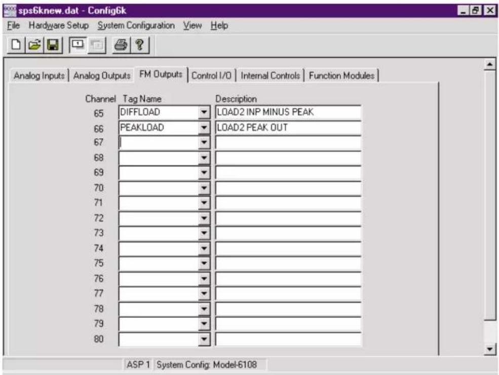
Fig. 3.13 Function Module Outputs Window
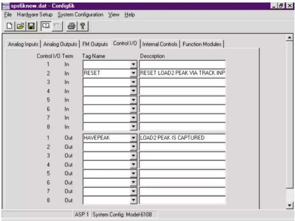
Fig. 3.14 Control I/O Window
- According to our block diagram (Fig. 3.11), the SPS6702's second analog output ("PEAKLOAD") should terminate at ASP Analog Output Channel No. 4. Since this is NOT the next available output channel (which is No. 3), we will NOT use the "autoconnect" function here.
Instead, click on the downward-pointing arrow to the right of the Tag Name field for Analog Output Channel No. 4. The popup menu shows the two presently available source-point tags for this output. Click on "PEAKLOAD" to select it.
-
We still have to assign "PEAKLOAD" to a function module output channel. Go back to the FM Outputs window by clicking on its tab. From the popup menu for Channel No. 66, select "PEAKLOAD." Press [Tab], and type in a description of "LOAD2 PEAK OUT" for Channel No. 66 (as in Fig. 3.13). Press [Tab] to allow you to exit the window.
-
The SPS6702's two analog outputs are now "terminated" at ASP1 Analog Output Channels 2 and 4, respectively (as required by our worksheet diagram). Now let's set the "terminating" point for the SPS6702's single logic output signal ("HAVEPEAK"). Go back to the SPS6702 Configuration window by clicking on the Function Modules tab, and then the SPS6702 tab (Socket No. 2).
-
Click the A/C button for the SPS6702's Have Peak field. This will automatically connect the "HAVEPEAK" function module logic output to the next available (presently unconnected) ASP control output, which is Control Output No. 1.
-
To verify the "autoconnection" of the SPS6702's "Have Peak" signal to Control Output No. 1, go to the Control I/O window by clicking on its tab. This window is shown in Fig. 3.14. Tag-name and description fields are provided for all eight CONTROL INPUTS and all eight CONTROL OUTPUTS of ASP Card No. 1. "HAVEPEAK" should appear in Output No. 1's Tag Name field.
-
Click on the Description field for Control Output No. 1 and type "LOAD2 PEAK IS CAPTURED" (as in Fig. 3.14). Then press [Tab].
-
While you are in the Control I/O window, you should complete the other SPS6702 I/O path that connects to ASP1's Control I/O terminals. The worksheet shows the single logic input to the SPS6702 to be sourced by ASP1's Control Input Terminal No. 2. From the popup menu for Control INPUT No. 2, select "RESET" (the only presently available source-point tag for this input), and press [Tab].
-
Now enter a description of "RESET LOAD2 PEAK VIA TRACK INP" for Control Input No. 2, and press [Tab].
All signal paths associated with the SPS6702 function module are now completely defined. (Note that in this configuration, we did not need to enter any tag names in the Internal Controls window.)
- Before closing the configuration, you should try the Validate command. A configuration that tests "invalid" for one or more reasons cannot be downloaded to an SPS6000 system, although it can be saved to disk. Before applying the Validate command, let's create a few deliberate configuration errors in the form of "open wires."

Fig. 3.15 Configuration Errors Window
- Bring the Analog Outputs window to the front by clicking on its tab.
- Enter a tag name of "BADTAG1" for Analog Output Channel No. 6, and press [Tab].
- Bring the Analog Inputs window to the front, enter a tag name of "BAD-TAG2" for Analog Input Channel No. 37, and press [Tab].
- Finally, bring the Control I/O window to the front, enter a tag name of "BAD-TAG3" for INPUT No. 5, and press [Tab].
- Select Validate from the File menu. The Configuration Errors window shown in Fig. 3.15 should be displayed.* After studying the errors, click OK.
- To remove these errors, bring the Analog Outputs window back to the front by clicking on its tab.
-
Delete "BADTAG1" from the window by clicking on the field and pressing the [Back Space] key (or the [Del] key). Then press [Tab].
-
Go to the Analog Inputs window, delete "BADTAG2," and press [Tab].
-
Finally, go to the Control I/O window, delete "BADTAG3," and press [Tab].
-
Select Validate from the File menu. You should now be told that the validation is successful. Click OK.
-
Select Exit from the File menu. You will be asked whether you wish to save the changes you have made to sps6Knew.dat since it was last saved (in Step 21). Answer Yes, and then answer OK to "Are you sure?" After you then click OK in the "saved successfully" message window, the Configurator program will quit.
* * *
Fig. 3.16 Tutorial Worksheet No. 3
![Daytronic RMK-6K - - Offset ([Entered Engineering Units]) - 6](/content/2026/06/1223924/images/d6221996833cd75a72c1acd0a0f80e236b7381166df8f835e3e2ea509a32a695.jpg)
flowchart
graph TD
    A["Control Outputs"] --> B["Analog Input Channels"]
    B --> C["Analog Output Channels"]
    C --> D["Control Inputs"]

    subgraph Control Outputs
        E["Chn 33"] --> F["Tag: POS(IN)"]
        G["Chn 34"] --> H["Tag: FORCE(IN)"]
        I["Chn 35"] --> J["Tag: GETSAMP1"]
        K["Chn 36"] --> L["Tag: GETSAMP2"]
        M["Chn 37"] --> N["Tag: (HAVE PEAK) 6702 (TRACK)"]
        O["Chn 48"] --> P["Tag: RESET"]
    end

    subgraph Analog Outputs
        Q["Chn 1"] --> R["Tag: SAMPLE1"]
        S["Chn 2"] --> T["Tag: POS(IN)"]
        U["Chn 3"] --> V["Tag: SAMPLE2"]
        W["Chn 4"] --> X["Tag: FORCE(IN)"]
        Y["Chn 5"] --> Z["Tag: PEAKFORCE"]
        AA["Chn 16"] --> AB["Tag: RESET"]
    end

    subgraph Analog Output Channels
        AC["Chn 1"] --> AD["Term 1"]
        AE["Chn 2"] --> AF["Term 2"]
        AG["Chn 3"] --> AH["Term 3"]
        AI["Chn 4"] --> AJ["Term 4"]
        AK["Chn 5"] --> AL["Term 5"]
        AM["Chn 16"] --> AN["Term 16"]
    end

    B -->|①| C
    C -->|②| D
    D -->|③| E
    E -->|④| F
    F -->|RESET| G
The remainder of this tutorial is devoted to the more complicated configuration illustrated in Fig. 3.16. You may feel at this point that you are sufficiently familiar with the workings of the Configurator to attempt to create your own configuration. If, however, you would like more practice in the art of configuration, you are encouraged to continue...
The Force/Displacement system diagrammed in Fig. 3.16 was discussed in Section 1.e.4. It involves
- two ASP1 ANALOG INPUTS
— Channel 33 ("POS(IN)"), located at Slot 2, Subchannel 1
— Channel 34 ("FORCE(IN)"), located at Slot 1, Subchannel 1
- five ASP1 ANALOG OUTPUTS
— Channel 1, Terminal 1 ("SAMPLE1")
— Channel 2, Terminal 2 ("POS(IN)")
— Channel 3, Terminal 3 ("SAMPLE2")
— Channel 4, Terminal 4 ("FORCE(IN)")
— Channel 5, Terminal 5 ("PEAKFORCE")
- five ASP1 FUNCTION MODULES
— Socket 1: Model SPS6702 Peak and Track/Hold Module
— Socket 2: Model SPS6704 Comparator Module in HI/LO Mode
— Socket 3: Model SPS6704 Comparator Module in HI/LO Mode
— Socket 4: Model SPS6702 Peak and Track/Hold Module
— Socket 5: Model SPS6702 Peak and Track/Hold Module
• one ASP1 CONTROL INPUT
— Control Input Terminal 1 ("RESET")
• three ASP1 CONTROL OUTPUTS
— Control Output Terminal 1 ("SAMP1HI")
— Control Output Terminal 2 ("SAMP1OK")
— Control Output Terminal 3 ("SAMP1LO")
- two ASP1 INTERNAL CONTROLS
— “High” output of the Model 9704 in ASP Socket 3 to “Acquire” input of the Model 9702 in ASP Socket 1 (“GETSAMP1”)
— “Have Peak” output of the Model 9702 in ASP Socket 4 to “Acquire” input of the Model 9702 in ASP Socket 5 (“GETSAMP2”)
CREATE NEW CONFIGURATION; SYSTEM CONFIGURATION; HARDWARE SETUP
- Repeat Steps 1 through 10, above.
- Select ASP 1 Function Module Assignments from the Hardware Setup menu, and make the assignments shown in Fig. 3.17.
- Click OK to return to the main ASP1 Configuration window.

Fig. 3.17 ASP1 Function Module Assignments for Step 76
ASP ANALOG INPUT CONFIGURATION
- If the Analog Inputs window is not already at the front of the set, click on the Analog Inputs tab in the ASP1 Configuration window.

Fig. 3.18 ASP1 Analog Input Tag Names and Descriptions for Step 79
- For ASP1 Analog Input Channel Nos. 33 and 34, enter the respective tag names and descriptions shown in Fig. 3.18.
- Select Channel No. 33 by clicking on its Tag Name field. Then click on the Configure... button.
- In the Input Configuration window that appears, assign Channel No. 33 ("POS(IN)") to the first subchannel of the Model 10A30-2C Dual LVDT Conditioner Card in "A Slot" No. 2. (This is the only setting you need to make in this window.)
- Click on the Next button to display the Input Configuration window for Channel No. 34 ("FORCE(IN)"). Assign Channel No. 34 to the first subchannel of the Model 10A72-2C Dual Enhanced Strain Gage Conditioner Card in "A Slot" No. 1. (This is the only setting you need to make in this window.)
- Click Close to return to the Analog Inputs window.
ASP ANALOG OUTPUT CONFIGURATION
- Bring the Analog Outputs window to the front by clicking on its tab.
- For ASP1 Analog Output Channel Nos. 1 through 5, enter the respective tag names and descriptions shown in Fig. 3.19. NOTE: The configuration calls for ASP Analog Output Channel Nos. 2 and 5 to be directly tied to the previ-

Fig. 3.19 ASP1 Analog Output Tag Names for Step 85

Fig. 3.20 SPS6702 I/O Tag Names for Step 87
ously named ASP Analog Input Channels (Nos. 33 and 34, respectively). Therefore, you need not type in the tag names for these two output channels, but may simply select their names from the popup list for the Tag Name field. The description text you entered in Step 79 for the "POS(IN)" and "FORCE(IN)" inputs will automatically appear for the corresponding outputs. The three remaining output channels are being given tag names that have not been previously entered, and will therefore have no descriptions for the moment.
FUNCTION MODULE CONFIGURATION
-
Bring the Function Modules window to the front by clicking on its tab.
-
For the single Analog Input, the "Output" Analog Output, and the "Acquire" Logic Input of the Model SPS6702 Peak and Track/Hold Module assigned to Socket No. 1, enter the tag names shown in Fig. 3.20. NOTE: You may use the field popup lists to select those names that have already been entered—that is,
— to tie the SPS6702 "Input" to the ASP "POS(IN)" input channel; and — to tie the SPS6702 "Output" to the ASP "SAMPLE1" output channel
However, you will have to type in the tag name "GETSAMP1" for the SPS6702's "Acquire" logic input.
-
Click on the Autoconnect ("A/C") button to the right of the SPS6702's Output field. A message will appear telling you that the "Tag already exists in analog outputs."
-
Click OK to acknowledge the message, and then click on the FM Outputs tab to bring that window to the front of the set. Note that "SAMPLE1" has been automatically assigned to the first function module output channel (No. 65).
- Enter a description of "POSITION AT HIGH FORCE" for Channel No. 65. Go back to the Analog Outputs window and verify that this description now appears for the output "SAMPLE1."
- Click on the Function Modules tab, and then on the tab for Socket No. 2.
- For the single Analog Input and the "High," "OK," and "Low" Logic Outputs of the Model SPS6704 Comparator Module assigned to Socket No. 2, enter the tag names shown in Fig. 3.21. NOTE: You may use the field popup list to tie the SPS6704 "Input" to the "SAMPLE1" analog output of the first SPS6702 module. However, you will have to type in the tag names for the three SPS6704 logic outputs.
- Click the A/C button to the right of the SPS6704's High field. Then click the A/C buttons for the OK and Low fields (in that order).
- Click on the Control I/O tab to bring that window to the front of the set. Note that "SAMP1HI," "SAMP1OK," and "SAMP1LO" have been automatically assigned to the first three ASP control output terminals.
- Click on the Function Modules tab, and then on the tab for Socket No. 3.
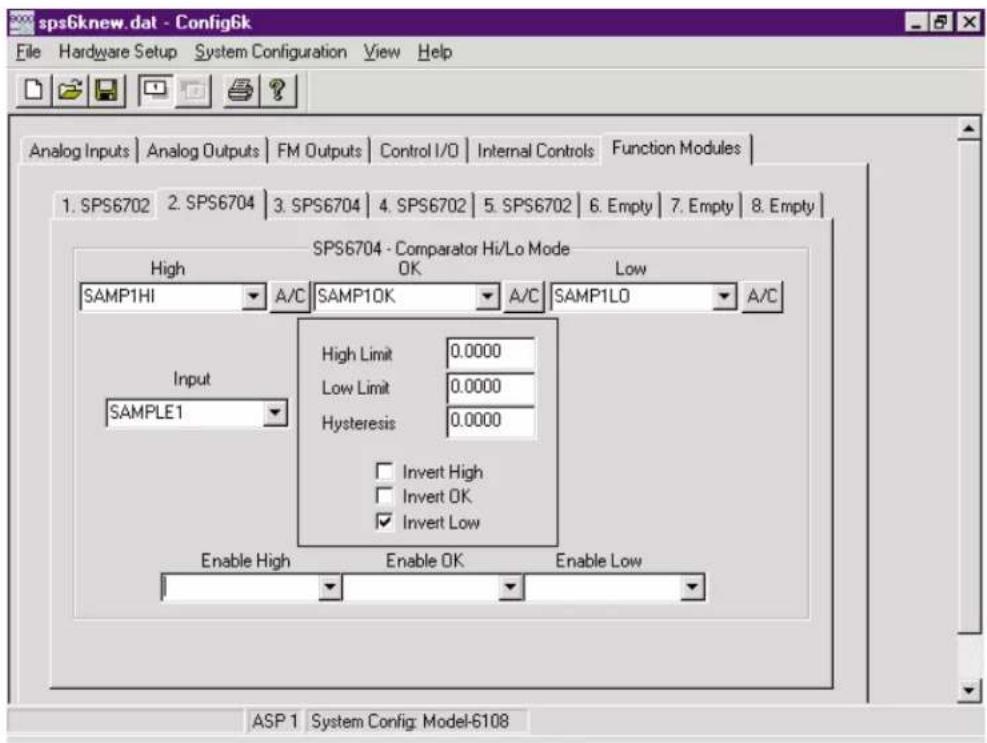
Fig. 3.21 SPS6704 I/O Tag Names for Step 92

Fig. 3.22 SPS6704 I/O Tag Names for Step 96
- For the single Analog Input and the "High" Logic Output of the Model SPS6704 Comparator Module assigned to Socket No. 3, enter the tag names shown in Fig. 3.22. NOTE: You may use the field popup lists to select both of these names, since both have been previously entered ("FORCE(IN)" as an ASP analog input and "GETSAMP1" as a logic input to the first SPS6702 module). Since "GETSAMP1" is a strictly "internal control" signal interconnecting two function modules—and is NOT to be connected to an ASP control output—you will NOT want to press its A/C button.
- Click on the tab for Socket No. 4.
- For the single Analog Input, the "Output" Analog Output, the "Track" Logic Input, and the single Logic Output of the Model SPS6702 Peak and Track/Hold Module assigned to Socket No. 4, enter the tag names shown in Fig. 3.23. NOTE: You may use the field popup lists to select the "Input" and "Output" tags, but you will have to type in the tag names for the "Have Peak" and "Track" logic signals. Since "GETSAMP2" is a strictly "internal control" signal, you will NOT want to press its A/C button.
- Click on the Output field's A/C button, and click OK when the "tag already exists" message appears.
- Click on the tab for Socket No. 5.
- For the single Analog Input, the "Output" Analog Output, and the "Acquire" Logic Input of the Model SPS6702 Peak and Track/Hold Module assigned to Socket No. 5, enter the tag names shown in Fig. 3.24. NOTE: You may

Fig. 3.23 SPS6702 I/O Tag Names for Step 98

Fig. 3.24 SPS6702 I/O Tag Names for Step 101

Fig. 3.25 ASP1 Function Module Output Tag Names and Descriptions for Step 104
use the field popup list to select each of these names, since all have been previously entered ("POS(IN)" as an ASP analog input, "SAMPLE2" as an ASP analog output, and "GETSAMP2" as a logic output from the second SPS6702 module).
- Click on the Output field's A/C button, and click OK when the "tag already exists" message appears.
- Bring the FM Outputs window to the front by clicking on its tab.
- For Function Module Output Channel Nos. 66 and 67 ("PEAKFORCE" and "SAMPLE2"), enter the descriptions shown in Fig. 3.25.
LOGIC I/O CONFIGURATION
- Bring the Control I/O window to the front by clicking on its tab.
- Connect ASP1 Control Input No. 1 to the "Track" logic input of the second SPS6702 module by selecting "RESET" from the field's popup list and by entering a description of "RESET FORCE PEAK."
- For the three previously connected ASP1 control ou_tputs, enter the descriptions shown in Fig. 3.26.
- Bring the Internal Controls window to the front by clicking on its tab.

Fig. 3.26 ASP1 Control I/O Tag Names and Descriptions for Step 107

Fig. 3.27 ASP1 Internal Control Names and Descriptions for Step 109
- In the first two (unnumbered) rows, enter the respective tag names and descriptions shown in Fig. 3.27.
- You may now wish to check the validity of your configuration by selecting Validate from the File menu. If the Configuration Errors window appears, note the type of error(s) displayed, and compare the pertinent configuration window(s) with the respective tutorial figure(s) (3.17 through 3.27).
We have finished "wiring" the configuration shown in Fig. 3.16. If this were your actual SPS6000 configuration, you would still have to
- SAVE the configuration (which you may wish to do anyway).
- Make sure that proper CALIBRATION VALUES are in effect for the two input channels (even if you intend to perform later "ON-LINE CALIBRATION").
- Make sure that appropriate FUNCTION MODULE CONFIGURATION PARAMETERS are in effect, if required by your application (e.g., the "Peak Mode," "Have Peak Threshold," and "Leak Rate" settings for each SPS6702; the "High Limit," "Low Limit," and "Hysteresis" settings for each SPS6704 in HI/LO Mode). See Appendix B for definitions of these parameters.
- Make sure that "logic inversion" is indicated (where allowed) for function module logic I/O that are to be at "Logic 0" when "true."
After attending to these remaining setup parameters, you would proceed to
- DOWNLOAD the configuration to the connected SPS6000 (Section 3.c.4)
- Perform any "ON-LINE CALIBRATION" required for the analog input channels (Section 3.e)
- Start collecting and processing real-world data
3.c CONFIGURATION MANAGEMENT
NOTE: USE OF A MOUSE WILL BE ASSUMED IN ALL OF THE FOLLOWING SECTIONS. For keyboard equivalents to basic mouse operations, see Section 3.a.4.
3.c.1 OPENING AN EXISTING CONFIGURATION
Select Open... from the File menu to open an existing disk-stored SPS6000 configuration (*.dat). You can also apply this command by clicking on the Open button in the toolbar (see Section 3.a.2.f). The standard Windows Open dialog box (Fig. 3.28) will appear, with the blinking insertion cursor in the (blank) File name field. The list box shows all “*.dat” files and folders presently stored in the destination folder that was specified when the software was installed (with an initial default of “Sps6000 Windows Configurator”).
To open any configuration file in the list, simply double-click on its name—or click once to place that name in the File name field, and then click on the Open button. If the configuration you wish to open is not in the destination folder, use the standard "Look In" browser field to locate it—or type its full path name (if known) in the File name field and click Open.
FOR FULL DETAILS CONCERNING THE USE OF THE OPEN DIALOG BOX, CONSULT YOUR WINDOWS DOCUMENTATION.
The currently open configuration will be closed before the specified configuration is opened. If the currently open configuration has any unsaved changes, you will be asked whether you wish to save these changes before it is closed. Answer Yes to "Save changes?" if you want to save the currently open configuration (without changing its present name and location). Answer No if you want to proceed with the "Open" operation without saving the currently open configuration. Press the Cancel button in the "Save Changes?" message box—or the Cancel button in the Open window—to abort the "Open" operation without closing the currently open configuration.
NOTE: You can quickly open any of the last four configurations to have been opened by selecting it from the Recent File list at the bottom of the File menu, just above the Exit command.

Fig. 3.28 Standard "Open" Window
3.c.2 SAVING THE OPEN CONFIGURATION
Select Save from the File menu to save the currently open SPS6000 configuration using its present name and location. You can also apply this command by clicking on the Save button in the toolbar (see Section 3.a.2.f).
When you apply the Save command to save a configuration for the first time, the software will display the standard Windows Save As dialog box (described in the following section), so that you may assign a name and location to your new configuration. When you apply Save to a previously saved configuration, that configuration will be automatically saved using its present name and directory, and no window or message will appear.
If you want to save the currently open configuration with a new name and/or location, choose the Save As... command from the File menu and see the following section.
NOTE: Do not confuse the Save command with the Save Online Changes command (also in the File menu). Save is used to store the presently open configuration as a configuration file in the setup computer; Save Online Changes (as explained in Section 3.e.4, below) is used to store the configuration that is currently loaded in the connected SPS6000 system in that system's nonvolatile memory.

Fig. 3.29 Standard "Save As" Window
3.c.3 SAVING THE OPEN CONFIGURATION AS ANOTHER CONFIGURATION
Select Save As... from the File menu to save a copy of the currently open configuration using a different name and/or location, and without changing or saving the original configuration (which will be closed by the "Save As" operation).
As soon as the Save As... command is applied, the standard Windows Save As dialog box (Fig. 3.29) will appear. The File name field will contain the name of the currently open configuration, already "selected" (white on blue) for editing. The list box shows all "*.dat" files and folders presently stored in the destination folder
that was specified when the software was installed (with an initial default of "SPS6000 Configurator").
In the File name field, enter the desired name for the configuration copy to be saved. If you wish to change the location to which it is stored, you may indicate the full path in the File name field, or use the standard "Look in" browser field to specify a new location. You will not normally want to change the Save as type designation from the default of "Sps6000 Config Files (*.dat)." The software will automatically add the ".dat" extension to the name that is entered in the File name field. When the specified name and location for the "Save As" configuration copy are satisfactory, click on the Save button.
If you wish to save the "Save As" copy using one of the names that appears in the displayed list, simply double-click on that name—or click once to place that name in the File name field, and then click on the Save button. You will be told that the file already exists and will be asked whether you want to replace it. Answer Yes to replace the existing file with the "Save As" copy. Answer No to return to the Save As window without replacing the existing file. You can abort the "Save As" operation without closing the currently open configuration by pressing the Cancel button in the Save As window.
FOR FULL DETAILS CONCERNING THE USE OF THE SAVE AS DIALOG BOX, CONSULT YOUR WINDOWS DOCUMENTATION.
3.c.4 DOWNLOADING THE OPEN CONFIGURATION TO THE CONNECTED SPS6000 SYSTEM
Select Download To SPS6000 from the File menu to download the currently open configuration to the connected SPS6000 system without changing or saving that configuration. The present name of the configuration—plus all present tag names and descriptions—will be included in the downloaded information.
As mentioned in Section 2.b.1, AFTER CHANGING THE CARD ASSIGNMENT OF AN ASP SLOT—BY ADDING, REMOVING, OR "SWAPPING" AN ASP CARD—YOU MUST RE-DOWNLOAD THE CONFIGURATION TO THE SPS6000 SYSTEM IN ORDER FOR IT TO WORK PROPERLY.
For connection of the SPS6000 mainframe to the setup computer and setup of the communications port, see Sections 2.b.5 and 3.a.5, respectively. OBVIOUSLY, NO DOWNLOAD CAN TAKE PLACE IF THIS SERIAL CONNECTION IS NOT VALID.
WARNING: BE CAREFUL NOT TO DOWNLOAD A CONFIGURATION THAT HAS MORE CONFIGURED CHANNELS THAN THE RECEIVING SPS6000 SYSTEM CAN PROCESS. For example, if you attempt to download a configuration with 32 active channels into an 8-channel SPS6000 unit, the data integrity of the resulting system will be seriously degraded.
WARNING: When you command Download To SPS6000, you will be told to be sure to DISCONNECT OR DEACTIVATE ANY DEVICE(S) CONTROLLED BY THE SPS6000 SYSTEM BEFORE DOWNLOADING A NEW CONFIGURATION INTO THAT SYSTEM. If you are sure that no active control devices are connected to the SPS6000 that will be affected by the downloading of a new configuration, you should answer Yes to "Are you sure you want to download the configuration." Otherwise, answer No to cancel the "Download" operation, after which you should disconnect or deactivate any and all such devices, before reattempting the download.
If you answer Yes, the software will automatically run a “validation” test on the currently open configuration. If any configuration errors are detected, the “Download” operation will be aborted, and you will be told that “Download failed due to invalid configuration.”
If you get this message, click OK to close it. You should then display the Configuration Errors window by selecting Validate from the File menu. Take note of the error(s) listed. The most common configuration errors include
- a tag name which has been entered for only one end of an ASP signal path (e.g., an “unterminated” ASP analog or control input; an “unterminated” function module output; an “unsourced” ASP analog or control output; an “unsourced” function module analog or logic input; or a “single-ended” internal control)
- a named analog input which has not been "located" to a specific conditioner card subchannel
ALL ERRORS MUST BE CORRECTED BEFORE THE DOWNLOAD WILL BE ALLOWED.
Assuming that (1) you have answered Yes to "Are you sure you want to download the configuration?"; (2) there are no outstanding configuration errors; and (3) the serial connection between the SPS6000 system and the setup computer is good—the Download To SPS6000 progress window will appear and the download will proceed.* You will be told when the download has been successfully completed. Click on the Close button to exit the completion message.
NOTE: THE DOWNLOADED CONFIGURATION IS AUTOMATICALLY PLACED IN THE NONVOLATILE MEMORY OF THE CONNECTED SPS6000 SYSTEM. THERE IS NO NEED TO APPLY A SAVE ONLINE CHANGES COMMAND FOLLOWING A DOWNLOAD.
To cancel a download in progress, click on the Cancel button in the Download To SPS6000 progress window. When downloading is aborted in this way, the SPS6000 configuration which was in effect when the download started will be restored in its entirety.
3.c.5 UPLOADING THE WORKING CONFIGURATION OF THE CONNECTED SPS6000 SYSTEM
Select Upload From SPS6000 from the File menu to upload the existing RAM-stored "working" configuration of the SPS6000 system connected to the setup computer. This configuration will include all of the latest "on-line" changes to have been made via the On-Line Calibration window and/or front-panel keypad/display, regardless of whether or not a Save Online Changes command was subsequently issued.
The currently open configuration will be closed before the uploaded configuration is opened. If the currently open configuration has NO unsaved changes, when you select Upload From SPS6000, you will be asked "Are you sure you want to upload the configuration?" Answer Yes to continue, or No to cancel (without closing the currently open configuration).
If, however, the currently open configuration has any unsaved changes, you will first be asked whether you wish to save these changes before it is closed. Answer Yes to "Save changes?" if you want to save the currently open configuration (without changing its present name and location). Answer No if you want to proceed with the "Upload" operation without saving the currently open configuration. Press the Cancel button in the "Save Changes?" message box to abort the "Upload" operation without closing the currently open configuration. If you answer either Yes or No, you will then be asked "Are you sure you want to upload the configuration?" Answer Yes to continue, or No to cancel (without closing the currently open configuration).
For connection of the SPS6000 mainframe to the setup computer and setup of the communications port, see Sections 2.b.5 and 3.a.5, respectively. OBVIOUSLY, NO UPLOAD CAN TAKE PLACE IF THIS SERIAL CONNECTION IS NOT VALID.
Assuming that (1) the currently open configuration has no unsaved changes; (2) you have answered Yes to "Are you sure you want to upload the configuration?"; and (3) the serial connection between the SPS6000 system and the setup computer is good—the Upload From SPS6000 progress window will appear and the upload will proceed. You will be told when the upload has been successfully completed. Click on the OK button to close the completion message. The name of the uploaded configuration will appear in the upper left corner of the Configurator window.
NOTE: AN UPLOADED CONFIGURATION IS NOT SAVED ON UPLOADING. THEREFORE, THE SAVE COMMAND SHOULD BE APPLIED TO AN UPLOADED CONFIGURATION SOON AFTER UPLOADING, EVEN IF NO CHANGES ARE SUBSEQUENTLY MADE TO THAT CONFIGURATION.
To cancel an upload in progress, click on the Cancel button in the Upload From SPS6000 progress window. When uploading is aborted in this way, the currently open configuration is not closed or changed.
3.c.6 PRINTING CONFIGURATION REPORTS
3.c.6.a SELECTING REPORT SECTIONS
Before you can print out a report of the currently open configuration via the Print... command, you must open the Reports window and select one or more report subsections to be printed. If no report subsections are presently selected in the Reports window, the Print... command will be disabled.
Select Reports... from the File menu. The Reports window (Fig. 3.30) will appear. Click on the report subsection(s) you wish to be printed when the Print... command is next applied. A selected section will be indicated by a checkmark inside the preceding box. To deselect a section, just click on it once more. To select all five reports, click on the All button.
When all report subsections to be printed have been selected, click OK to accept the existing selection(s) and to open the standard Windows Print dialog box (unless no report subsections have been selected—see Section 3.c.6.b). Click on the Cancel button to close the Reports window without changing the selection(s) that were in effect when it was last opened.

Fig. 3.30 Reports Window
Note that each time the Configuration software is started, the last report selections to have been made prior to the last software shutdown will still be in effect.
The Hardware section of the configuration report includes
• the Configurator Software version
- the user-entered "description" of the configuration
- SPS6000 "model" information (including capacity of each installed ASP card)
- slot "locations" of installed conditioner cards
- ASP socket "locations" of installed function modules
The ASP1 (or ASP2) section of the report gives complete information—including tag names, descriptions, connections, and special parameters (where applicable)—for the ASP card's analog output channels; analog input channels; function module output channels; control inputs and outputs; and function modules.
The Security section of the report gives, for every active system channel, the "On/Off" status of each keypad button/function for each connected display/key-pad unit (see Section 3.f for a complete explanation).
The Validation section of the report lists any and all errors in the currently open configuration that require correction before the configuration may be downloaded to the SPS6000 system. Note that the Configuration Errors window has its own Print button to initiate printout of this section of the report (only).
3.c.6.b PRINTING THE REPORT
The Configurator Software provides the following standard Windows printout functions. FOR FULL DETAILS CONCERNING THE USE OF EACH OF THESE FUNCTIONS, CONSULT YOUR WINDOWS DOCUMENTATION.
- a Print Setup... command in the File menu, which opens the standard Windows Print Setup dialog box for entry of paper size, page orientation, and other printing options (which will vary depending on the type of printer you are using)
- a Print Preview command in the File menu, which activates the standard Windows Print Preview function, showing what the selected configuration
report section(s) will look like when printed. You can initiate the actual print-out from the Print Preview window, if desired.
- a Print... command in the File menu—also issued via the Print button in the toolbar and the OK button in the Reports window—which opens the standard Windows Print dialog box, to allow printing of the configuration report section(s) currently specified in the Reports window (see above). If no report sections are presently selected, the Print... command will be disabled.
3.d ON-LINE SELECTION OF ANALOG FILTERING
THIS SECTION APPLIES ONLY TO ASP1 OR ASP2 ANALOG INPUT CHANNELS (NOS. 33 THROUGH 64) "SOURCED" BY "AA" CONDITIONER CARDS THAT ARE EQUIPPED WITH PROGRAMMABLE FILTERING.
In System 10 and the SPS8000 System, the optional programmable analog filter for an active "AA"-card data channel is normally set by means of a 16-position switch on the card itself. THIS IS NOT THE CASE WITH SPS6000. In the process of creating a configuration for your SPS6000 system, you will specify an individual corner frequency for the analog filter of each active "AA"-based input channel via that channel's Input Configuration window, as explained in Step 33 of the Tutorial (Section 3.b).*
If it is later necessary to modify that filter setting (on a purely “run-time” basis), this may be done either
- via the Filter button in the Configurator Software's On-Line Calibration window (Fig. 3.31, below); or
- via the SPS6000 unit's front-panel Filter button, if this button has not been disabled for the input channel in question by means of the "security" settings discussed in Section 3.f.
IMPORTANT: TO ENABLE THE CONFIGURATOR SOFTWARE OR OPTIONAL FILTER BUTTON TO SET THE ANALOG FILTER OF A GIVEN "AA"-CARD CHANNEL, THE FILTER SELECTION SWITCH FOR THAT CHANNEL MUST FIRST BE SET TO "F."
Therefore, the following steps should be taken before using the Configurator Software or optional Filter button for the first time to enter or modify an active "AA"-card channel's analog filter setting:
- Remove the "AA" card from its mainframe slot (see Section 2.b.1 for "Card Insertion and Removal").
- Locate the card's FILTER SELECTION SWITCHES between the main board and the filter tile(s) (you may wish to refer to the appropriate figure in Appendix A).
- Make sure that the FILTER SELECTION SWITCH for each active channel is set to "F." You will need to use a small screwdriver (or equivalent tool) to reset the switch, if necessary.
* The analog filter setting for an UNUSED "AA"-card channel is immaterial, and will not affect operation of the card.
- Reinsert the "AA" card.
The Filter button in the On-Line Calibration window or on the front-panel display/keypad can always be used to read the currently effective analog filter setting for a given "AA"-card input channel (No. 33 through 64). As mentioned above, it can also be used to change that setting on a strictly temporary "runtime" basis. Any filter change made via the Filter button is stored in volatile RAM, and will be lost on interruption of power. A Save Online Changes command MUST be applied through the Configurator Software or front panel in order for a filter change made via the Filter button to become part of the SPS6000 unit's "permanent" (EEPROM-stored) configuration.
When using the On-Line Calibration window's Filter button for temporary modification of an "AA"-card input channel's analog filter setting, you should
- Select the Calibrate... command from the File menu. This will display the On-Line Calibration window (shown in Fig. 3.31 and described in greater detail in the following section).
- Display the analog input channel whose filter setting you wish to change, as explained in Section 3.e.2.
- Click once on the Filter button, which will become highlighted to indicate that it is "ON." The channel's present analog-filter cutoff frequency (in Hz) will be displayed in the "Data" field, instead of its "live" data reading. (The displayed frequency will initially be the same that which was entered in the Filters field of the channel's Input Configuration window when the configuration that was last downloaded to the SPS6000 unit was being created).
- You may now use the Up or Dn button to the right of the "Data" field to step to the desired frequency value (again, in Hz).
- When the desired frequency is displayed, click on the Filter button once again to turn that button "OFF" and to return the channel to its normal "live" data display. Although stored only in volatile RAM, the new filter setting will go into effect immediately.
The procedure for changing an "AA"-card input channel's filter setting via the front-panel Filter button is very similar. The only real difference is that you must press and HOLD DOWN the keypad's Filter button as you step to the desired frequency value by pressing the UP ARROW or DOWN ARROW button to the right of the "Data" display.
Again, the change effected by the software or hardware Filter button is only a "run-time" change. To make the new filter setting "permanent"—so that it will be automatically invoked every time the SPS6000 system is subsequently powered up—YOU MUST APPLY A SAVE ONLINE CHANGES COMMAND, as explained in Section 3.e.4.*

Fig. 3.31 On-Line Calibration Window
3.e ON-LINE CALIBRATION OF INPUT CHANNELS
3.e.1 DISPLAY/KEYPAD VS. SOFTWARE "ON-LINE" CALIBRATION WINDOW
This section concerns the display of "live" SPS6000-acquired data and the application of "on-line" calibration techniques to "live" SPS6000 analog input channels by means of either
- the SPS6000 unit's front-panel display/keypad or any of up to three "remote" Model 6501 Display/Keypad Units that may be connected to an SPS6000 system (see Fig. 1.7); or
- the On-Line Calibration window provided by the Configurator Software (shown in Fig. 3.31, above), which is basically a software emulation of the physical display/keypad
Unless otherwise indicated, the following discussion will not distinguish between these two modes of "live" data display and operator interaction. The only practical differences between them are as follows:
-
When you are instructed below to "press" a button, this means that
-
if you're working from a display/keypad, you will physically press the button; but
- if you're working from the On-Line Calibration window, you will click on the button (or step to the button via [Tab] or [Shift][Tab] and, when the button is "selected," press the [Space Bar])
NOTE: All buttons in the On-Line Calibration window that place the system in data-entry mode will "latch" ON or OFF when clicked. Thus, for example, to enter a "zero" calibration point via the On-Line Calibration window, you would click once on the Zero button (which becomes highlighted to indicate that it is "ON"). Then you would modify the displayed "Data" value, either by means of the Up or Dn button, or by typing in a numeric value in the Data Entry window. When the desired "zero" point is displayed, you would click the Zero button once again to turn it "OFF" and return the system to its nor-
mal measurement mode. While the system is in data-entry mode, all buttons not associated with the activated configuration operation will be dimmed, to show that they have been temporarily disabled.
Buttons on the display/keypad that place the system in a data-entry mode do not "latch," but MUST BE HELD DOWN BY THE OPERATOR while the displayed "Data" value is being modified. Thus, to enter a "zero" calibration point via the front-panel display/keypad or a remote Model 6501, you need to press the Zero button, and continue to press it as you increment or decrement the displayed value until the desired zero-point value is reached. While the system is in data-entry mode, the keypad's red "Active" light will be ON (signifying that the presently displayed value is editable "configuration data" and NOT "live measurement data").
- The On-Line Calibration window allows quick entry of numeric calibration data via the Data button, as explained in the following manual sections, whereas the physical display/keypad requires the operator to use the "data increment" and "data decrement" buttons (only) for this purpose.
- The On-Line Calibration window provides a button for direct application of the Save Online Changes command. Application of this command via the physical display/keypad requires a special procedure that uses the "data increment" button and the display of Channel Nos. 97 and 99. Note, however, that with the physical display/keypad (only), Channel Nos. 98 and 99 allow the operator to cancel any unsaved "online changes" by restoring to the SPS6000's working memory the last configuration to have been saved to non-volatile EEPROM. See Section 3.e.4 for complete details.
- In order for the On-Line Calibration window to work, there must be a valid serial connection between the SPS6000 system and the setup computer (see Sections 2.b.5 and 3.a.5).
- With respect to the On-Line Calibration window in normal data display mode, a given button will be active only when it is applicable to the type of channel currently being displayed. For example, the software +Shunt and -Shunt buttons will be active only if the displayed channel is sourced by a strain gage conditioner card capable of "Simulated (Shunt)" calibration; the Output Volts button will be active only if the displayed channel is an ASP ANALOG OUTPUT; etc. All inactive buttons in the On-Line Calibration window will be dimmed.
With respect to a display/keypad in normal data display mode, a given button will be active only when it is applicable to the type of channel being displayed AND has not been disabled by the current "Security" settings for that display (or, if it has been so disabled, the HARDWARE JUMPER OVERRIDE is in effect (see Section 3.f)). When any inactive keypad button is pressed, a series of dashes will be displayed.
To display the On-Line Calibration window, select Calibrate... from the File menu.*
IMPORTANT
THE ON-LINE CALIBRATION WINDOW TAKES ITS SEQUENCE OF "DISPLAYABLE" CHANNELS FROM THE CURRENTLY OPEN CONFIGURATION. THEREFORE, TO ENSURE THAT THESE CHANNELS CORRESPOND TO THE WORKING CHANNELS OF THE CONNECTED SPS6000 SYSTEM, YOU SHOULD ALWAYS APPLY THE UPLOAD FROM SPS6000 COMMAND (Section 3.c.5) PRIOR TO USING THE ON-LINE CALIBRATION WINDOW.
THE UPLOAD WILL CLOSE THE CURRENTLY OPEN CONFIGURATION—HAVING FIRST PROMPTED YOU TO SAVE ANY UNSAVED CHANGES—AND WILL THEN DISPLAY THE CONFIGURATION PRESENTLY STORED IN THE NONVOLATILE EEPROM MEMORY OF THE CONNECTED SPS6000 UNIT.
ALSO NOTE: In the present SPS6000 release, the Hi Lim(it) and Lo Lim(it) buttons are not functional. Also, except for analog input channels sourced by an "AA" conditioner card with programmable filtering (see the previous section), the Filter button only provides a display of the fixed analog filter setting of the displayed channel.
3.e.2 DISPLAYING ACTIVE CHANNELS
Every SPS6000 channel to which a TAG NAME has been given can be called to the "live" display. This includes every tagged channel from each of the following subranges:
1 - 16 ASP1 ANALOG OUTPUT CHANNELS
17 - 32 ASP2 ANALOG OUTPUT CHANNELS
33 - 48 ASP1 ANALOG INPUT CHANNELS
49 - 64 ASP2 ANALOG INPUT CHANNELS
65 - 80 ASP1 FUNCTION MODULE OUTPUT CHANNELS
81 - 96 ASP2 FUNCTION MODULE OUTPUT CHANNELS
The number of the channel presently on display is shown by the "Channel" display in the lower left corner of the window or front panel. Use the Up (or UP ARROW) button to the right of the channel-number display to step upwards through the series of active (tagged) channels, one channel at a time. To step downwards through the series of active channels, use the Dn (or DOWN ARROW) button.
NOTE: After “on-line” configuration changes have been made either via the On-Line Calibration window or display/keypad—and until a Save Online Changes command has been issued to the SPS6000—Channels 97, 98, and 99 can also be called to the front-panel display (but not to the software window). These channels are used in the application of a Save Online Changes command via the front panel, and in restoring the last saved configuration (see below).
3.e.3 DISPLAYING OUTPUT VOLTAGES
You can display any ASP ANALOG OUTPUT CHANNEL (ONLY) as a pure voltage reading, instead of as a scaled engineering-unit answer. Thus, when any channel from 1 through 32 is on display, you can press the Output Volts button to read the channel's unscaled voltage level. ^1
On the physical display/keypad the Output Volts button will "latch" ON or OFF, as it does in the On-Line Calibration window (you need not continue to hold it down). The display/keypad's red indicator above the Output Volts button will light to tell you that output voltage is being displayed. To return to the scaled output reading, just press the Output Volts button again.
3.e.4 SAVING OR CANCELLING ON-LINE CHANGES
Following the “on-line” calibration of SPS6000 analog input channels by one or more of the techniques described below—or following an “on-line” change in an input channel's analog filter cutoff frequency as described in Section 3.d—YOU WILL USUALLY WANT TO APPLY A SAVE ONLINE CHANGES COMMAND TO THE SPS6000 SYSTEM. ^2
This command will save the last configuration to have been downloaded into the SPS6000 system—along with all newly established calibration and/or analog filter values—in the SPS6000's nonvolatile EEPROM memory. The saved configuration will be automatically invoked every time the SPS6000 system is subsequently powered up.
There are three ways to apply the Save Online Changes command. You can either (1) select Save Online Changes from the File menu; (2) click the Save Online Changes button in the On-Line Calibration window (if it is on display); or (3) perform the procedure given below for applying this command from a front-panel or "remote" display/keypad.
When applying the Save Online Changes command via the Configurator Software, you will be told that the application of multiple saves will affect the remaining "write life" of the SPS6000's internal storage. ^3 You will be asked whether you want to issue the save command to the SPS6000. Answer Yes to continue or No to cancel. When you answer Yes, a Save command will be immediately sent to the connected SPS6000 unit, thereby transferring its currently executing configuration to EEPROM. A message should then appear telling you that the Save Online Changes command was successful. Click OK to exit the message.
To apply the Save Online Changes command via the optional front-panel display/keypad, you should:
- Step to a display of Channel No. 97. (This special channel can be displayed only when unsaved "on-line" changes have been made through either the software or the physical display/keypad.) The "Data" display will read
SAVE?
- To answer "Yes," press the UP ARROW key to the right of the "Data" display (NOT the "Channel" display). To cancel the save operation at this point, just call another channel to display. If you answer "Yes," Channel No. 99 will be automatically displayed, and you will be asked whether you are
SURE?
you want to issue the Save command to the SPS6000 system.
- Again, press the "Data" UP ARROW key to answer "Yes," or call another channel (other than No. 97) to cancel the save operation. As soon as you answer "Yes," the last on-line changes will be saved.
Via the display/keypad (ONLY), you can cancel any unsaved "online" configuration changes and restore to the SPS6000's working memory the last configuration to have been saved to nonvolatile EEPROM. To do so, you should
- Step to a display of Channel No. 98. (Like Channel No. 97, this special channel can be displayed only when unsaved "on-line" changes have been made through either the software or the physical display/keypad.) The "Data" display will read
RESTORE?
- To answer "Yes," press the UP ARROW key to the right of the "Data" display (NOT the "Channel" display). To cancel the restore operation at this point, just call another channel to display. If you answer "Yes," Channel No. 99 will be automatically displayed, and you will be asked whether you are
SURE?
you want to issue the Restore command to the SPS6000 system.
- Again, press the "Data" UP ARROW key to answer "Yes," or call another channel (other than No. 98) to cancel the restore operation. As soon as you answer "Yes," the last on-line changes will be cancelled.
3.e.5 CALIBRATION: CALCULATED VS. ON-LINE
In Step 36 of the Configurator Software tutorial (Section 3.b.), we described the four CALIBRATION VALUES the user would normally enter in the channel-specific Input Configuration window in the course of configuring a channel "sourced" by a Model 10A72-2C Dual Enhanced Strain Gage Conditioner Card. There we stated that the calibration entries for different types of input channels will vary. For example, for a channel being used to measure voltage, current, or frequency itself, you would not normally be called on to enter any "Transducer Information," since accurate calibration can be calculated solely from the entered "Output Information."*
To repeat what was said in Section 3.b. (in case you weren't paying attention): For many types of channels, the software-calculated calibration based on the values entered in the channel's Input Configuration window will be quite sufficient.
However, if an input channel's exact transducer characteristics are not known, or if the final measurement accuracy provided by software-calculated calibration does not meet the requirements of the measurement application, additional "ONLINE CALIBRATION" can be performed for those channels which allow a conventional "zero and span" technique.* This includes all of those channels whose output is not being used to measure voltage, current, or frequency itself, but is rather an analog of some other parameter (force, strain, displacement, etc.).
The buttons labelled Engrg Units and Elect Units allow inspection (where applicable) of the values that represent the full scale of the displayed channel's "source" transducer, in appropriate engineering units and electrical units, respectively.
Thus, pressing the button labelled Engrg Units will display the current value of "FULL SCALE RANGE (ENGINEERING UNITS)" for the displayed channel as long as the button is "ON." As stated in Section 3.b, this number, when entered in the Input Configuration window, represents the full-scale rating of the channel's source transducer, expressed in the engineering units that have been chosen for the channel, as specified by the transducer manufacturer (e.g., for a load cell, 5000 (pounds, full-scale)).
Pressing the button labelled Elect Units will display (as long as the button is "ON") the current value of "FULL SCALE OUTPUT (ELECTRICAL UNITS)" for the source transducer of the displayed channel—but only when the relationship between the transducer's electrical output and the calibration parameters in the Input Configuration window is direct (when this is not the case, a series of dash-es will be displayed).
3.e.6 Two-Point (DEADWEIGHT) CALIBRATION
This conventional “zero and span” calibration technique should be used to improve on the “calculated” software provided by the Configurator Software when the transducer signal is relatively linear and when there are at least two independently and accurately known calibration values. The general procedure is given below.
NOTE: THE SOFTWARE WILL INFORM YOU IF A PROBLEM IS ENCOUNTERED IN ATTEMPTING TO "ZERO" OR "SPAN" THE DISPLAYED CHANNEL VIA THE ONLINE CALIBRATION WINDOW. OBVIOUSLY, THIS ERROR MESSAGE WILL APPEAR IF THAT CHANNEL IS NOT CONTAINED IN THE ACTUAL CONFIGURATION OF THE CONNECTED SPS6000 UNIT—THAT IS, IF THE SOFTWARE-DISPLAYED CONFIGURATION AND THE WORKING CONFIGURATION OF THE CONNECTED SPS6000 SYSTEM DO NOT MATCH (in which case the working configuration should be UPLOADED as explained in Section 3.c.5).
a. Perform a nominally accurate "calculated" calibration of the channel, as explained in Step 36 of the tutorial and in the respective section of Appendix A.
b. Enter the first calibration point ("zero") via the display/keypad or via the Configurator Software's On-Line Calibration window, as follows:
* Keep in mind that for software-calculated calibration, the resulting accuracy is limited to either the stated "initial offset" accuracy or the stated "gain accuracy" of the respective conditioner card, whichever represents a greater error value (see Appendix A for these specifications).
- Establish a zero input for the channel to be calibrated by removing all load from the source transducer, if this is possible. If it is impossible or inconvenient to produce a transducer input of zero—as, for example, with absolute pressure measurements, or with gaging operations where only a "Low Master" and "High Master" are employed—then you can use a nonzero first point.
- Press the Zero button.
If you are using a physical display/keypad, you must continue to hold the button down. The "Data" display will become "Active," as indicated by the red light. This means that you can now enter a numeric value.*
- If you are using a physical display/keypad, continue to hold down the Zero button as you use the UP/DOWN ARROW buttons to the right of the "Data" display to increment or decrement the displayed number until it equals the known measurement corresponding to the "zero" input, expressed in appropriate engineering units and with appropriate polarity. Then release the Zero button. This sets the ZERO OFFSET to be applied to the channel's measurement reading.
NOTE: Each time an arrow button is pressed, it will increment (or decrement) the displayed number by one count of its least significant digit.
If you are using the software's On-Line Calibration window, you can simply type in the value to be entered, as an alternative to using the Up and Dn buttons to the right of the "Data" display. To do this, click on the Data button (which became active when you pressed Zero). The Data Entry window (Fig. 3.32) will be displayed, asking you to "Enter new value." Type in the number you wish to enter and click OK. The entered value will be rounded off to the precision of the data display. After the Data Entry window closes, the Zero button in the On-Line Calibration window will be automatically turned "OFF."
- As soon as the Zero button is "OFF," the entered "zero" point is downloaded to the SPS6000 system's working memory. The display returns to a "live" channel reading, and (if you are using a display/keypad) the "Active" light goes off.
c. Enter the second calibration point ("span"), as follows:
- Apply an accurately known value of input loading to the source transducer—a value (positive or negative) from 80% to 100% of the nominal full-scale rating.
- Press the Span button. If you are using a physical display/keypad, you must continue to hold the button down. The "Data" display will become "Active," as indicated by the red light.
- Enter the known measurement corresponding to the "span" input, expressed in appropriate engineering units and with appropriate polarity. This sets the SCALING FACTOR to be applied to the channel's measure-

Fig. 3.32 Data Entry Window
ment reading. Again, the Data button will be activated when you press Span, thus allowing you to type in the desired value directly (as in Step 3, above).
- As soon as the Span button is released (or OK is clicked in the Data Entry window), the entered "span" point is downloaded to the SPS6000 system's working memory. The display returns to a "live" channel reading, and (if you are using a display/keypad) the "Active" light goes off.
Following on-line two-point calibration of an SPS6000 input channel, you can at any time check the validity of calibration by going to the channel's Input Configuration window and comparing the last-entered value of TRANSDUCER FULL-SCALE OUTPUT (IN ELECTRICAL UNITS) with the corresponding "Calibrated" value displayed in the window—and also the last-entered value of OUTPUT OFFSET (IN ENGINEERING UNITS) with the corresponding "Calibrated" value. As explained Step 36 of the Tutorial (Section 3.b), these displayed "calibrated" parameters represent the actual value of full-scale transducer output and the actual value of output offset currently in effect within the SPS6000 system. For a properly calibrated channel, there should be little difference between each actual "calibrated" value and the corresponding stored (user-entered) value. Ideally, the two values should be equal.
REMEMBER: APPLY A SAVE ONLINE CHANGES COMMAND FOLLOWING THE ENTRY OF ALL ZERO AND FORCE VALUES, IN ORDER TO SAVE THE NEW CALIBRATION DATA TO NONVOLATILE MEMORY (see Section 3.e.4, above).
3.e.7 SIMULATED (SHUNT) CALIBRATION OF STRAIN GAGE CHANNELS
This method is similar to the two-point (deadweight) procedure given above. The difference is that the second ("span") input is not produced by loading the source transducer, but by "simulating" a particular up-scale value of mechanical input. This known EQUIVALENT INPUT then serves to determine the SCALING FACTOR for the channel.
Simulated calibration is applied principally to Strain Gage Transducers, where the equivalent input is produced by shunting a resistor of known magnitude across one arm of the strain gage bridge, thereby simulating a known value of mechanical input for either a positive or negative upscale reading. If the transducer manufacturer has supplied the exact value of the transducer's equivalent input, it can be used as a reference point for calibrating the channel.
Equivalent input can be approximated from a knowledge of the Shunt Calibration Resistance (R), the transducer's Bridge Resistance (B), and the transducer's Full-Scale Sensitivity (K, in mV/V full scale). To determine the EQUIVALENT INPUT (X) as an approximate percentage of full-scale output, you may use the following equation:
$$ \mathbf {X} = 25000 \mathbf {B} / \mathbf {K} (\mathbf {R} + 0.5 \mathbf {B}) \% $$
Since the equivalent input is here expressed as a percentage of full-scale output, you must multiply it by the rated full-scale capacity of the transducer, in order to determine the actual input simulated by the shunt. This is the value you will enter in Step c.2, below.
Shunt calibration is an easier though generally less accurate technique then two-point (deadweight) calibration. It is useful, however, when overall “deadweighting” is impossible or inconvenient, and is good for an accuracy of about 0.2% (depending, of course, on the accuracy of the specified equivalent input, and on the resistor/bridge tolerance and temperature).
a. Perform a nominally accurate "calculated" calibration of the channel, as explained in Step 36 of the tutorial and in the respective section of Appendix A.
b. Enter the first calibration point ("zero") by following Steps b.1 - b.4 in Section 3.e.6, above.
c. Switch in the shunt resistor and enter the second calibration point ("span"), as follows:
- Press either the +Shunt or the -Shunt button, depending on whether you want a positive or negative equivalent input, respectively. The shunt will be applied and the "Data" display will become "active." (As with the Zero and Force buttons, if you are using a physical display/keypad, you need to hold the +Shunt or -Shunt button down while you adjust the displayed "data" value via the UP/DOWN ARROW buttons.)*
- Now enter the actual input simulated by the shunt, expressed in appropriate engineering units and with appropriate polarity. This sets the SCALING FACTOR to be applied to the channel's measurement reading. As in the "two-point" procedure, above, the Data button in the On-Line Calibration window will be activated when you press +Shunt or -Shunt, thus allowing you to type in the desired value directly.
- As soon as the +Shunt or -Shunt button is released (or OK is clicked in the Data Entry window), the entered "shunt span" point is downloaded to the SPS6000 system's working memory. The display returns to a "live" channel reading, and (if you are using a display/keypad) the "Active" light goes off.
NOTE: THE SOFTWARE WILL INFORM YOU IF A PROBLEM IS ENCOUNTERED IN ATTEMPTING TO "ZERO" OR "SPAN" THE DISPLAYED CHANNEL DURING SHUNT CALIBRATION VIA THE ON-LINE CALIBRATION WINDOW. OBVIOUSLY, THIS ERROR MESSAGE WILL APPEAR IF THAT CHANNEL IS NOT CONTAINED IN THE
ACTUAL CONFIGURATION OF THE CONNECTED SPS6000 UNIT—THAT IS, IF THE SOFTWARE-DISPLAYED CONFIGURATION AND THE WORKING CONFIGURATION OF THE CONNECTED SPS6000 SYSTEM DO NOT MATCH (in which case the working configuration should be UPLOADED as explained in Section 3.c.5).
REMEMBER: APPLY A SAVE ONLINE CHANGES COMMAND FOLLOWING THE ENTRY OF ALL ZERO AND ±SHUNT VALUES, IN ORDER TO SAVE THE NEW CALIBRATION DATA TO NONVOLATILE MEMORY (see Section 3.e.4, above).

Fig. 3.33 Display Window (for Display 1)
3.f SECURITY SETTINGS FOR DISPLAY/KEYPAD
The Configurator Software's Display windows let you disable one or more of the keypad buttons that apply to any SPS6000 system channel (review the channel-number ranges listed in Section 3.e.2, above). If you have multiple displays, keypad security can be set up differently, if desired, for each display.
The submenu that appears when you select Display from the System Configure menu lets you activate (i.e., bring to the front of the set) any of four independent Display windows—one for each of the four possible displays supported by the SPS6000 (see Fig. 3.33, above). All four windows will always be accessible, regardless of how many displays are actually connected to the SPS6000 mainframe.* While in the main Display window, click on the "tab" of any given display (1 through 4) to bring its window to the front.
Each horizontal row of the Display window is dedicated to a specific system channel, and shows—as separate columns—eight keypad buttons plus two actions relating to the +Shunt and -Shunt buttons (described below), as they apply to that channel. Buttons marked with hyphens [—] are NOT ACTIVE FOR
THAT CHANNEL, and therefore cannot be enabled or disabled.** To scroll down the channel list, you can use the scroll bar to the right of the button array, or you can use the keyboard's PageUp and PageDown keys.
NOTE
The +Shunt or -Shunt button (when active) performs two separate operations on the currently displayed strain gage input channel: (1) it establishes the actual shunt connection via the channel's installed calibration resistor, to yield a positive or negative upscale reading, respectively; and (2) it allows entry of a "span" calibration point corresponding to the ± input simulated by the shunt. The Configurator Software lets you secure these two action separately, if desired.
The Display-window column labelled "SView" applies to the first function of the display/keypad's +Shunt and -Shunt buttons—i.e., viewing the respective upscale reading produced by application of the calibration shunt. When this function is "Off" for a given strain gage channel, that channel's reading will not be affected when either of the Shunt buttons is pressed, because the button will NOT complete the shunt.
The column labelled "SAltr" applies to the second function of the Shunt buttons—i.e., rescaling the channel by altering its currently effective "span" range. When this function is "Off" for a given strain gage channel, the user will NOT be allowed to modify its present scaling when either of the Shunt buttons is pressed.
NOTE: A channel's SView function must be "On" in order for the SAltr function to work for that channel. Your three choices are therefore
- to turn both functions "Off," so that the Shunt buttons do nothing
- to turn both functions "On," so that the Shunt buttons operate as described in Section 3.e.7
- to turn SView "On" and SAltr "Off," so that the Shunt buttons display the respective shunt readings, but do not allow respanning of the channel
When a channel is initially defined by an appropriate tag name assignment, all available button functions for that channel will be automatically enabled. An enabled button is represented in the Display window by the word "On."
To DISABLE a presently enabled button function for any given channel, you need only click on that button in the Display window's button array. The button's "On" designation will change to "Off."
NOTE: A "READ/WRITE" keypad button is one that not only allows the operator to view the current value of a given setup parameter, but also to modify that value. The Filter button is an example of a READ/WRITE button when the displayed channel is sourced by an "AA" card with programmable analog filtering. When a READ/WRITE button is disabled (or turned "Off") as a result of its current Display-window setting, that button will still be able to READ the associated setup data. What is turned "Off" is its ability to change that data.
To RE-ENABLE a presently disabled button for any given channel, again you need only click on that button to change its state designation back to "On." If you are working via the keyboard, you can enter the button array via the [Tab] key, step to the button to be disabled or re-enabled via the four ARROW keys, and then press the Space Bar to toggle its state between "On" and "Off."
To DISABLE all active buttons for any given channel, you should
- Select the channel by clicking on its number in the leftmost (channel-number) column. This will highlight the channel's entire row of button functions.*
- Click on the Clear button. All active button functions for the channel will be turned "Off."
To RE-ENABLE any and all disabled buttons for any given channel, use the same procedure, but click on the Set button to turn "On" all active buttons in the channel's row.
To DISABLE a given button for all channels for which that button is active, you should
- Click on the name of the button at the top of its column. This will select the entire column, whose contents will be highlighted.**
- Click on the Clear button. All active buttons in the column will be turned "Off."
To RE-ENABLE a given button for all channels for which that button is active, use the same procedure, but click on the Set button to turn "On" all active buttons in the column.
IMPORTANT: THE DISPLAY/KEYPAD SECURITY SETTINGS OF THE CURRENTLY OPEN CONFIGURATION WILL NOT BE EFFECTIVE UNTIL THAT CONFIGURATION HAS BEEN DOWNLOADED TO THE CONNECTED SPS6000 SYSTEM (see Section 3.c.4).
The Display window also permits a "Hardware Jumper Override" function to be either enabled [X] or disabled [ ]. This refers to the Security Override Programming Jumper located on the SPS6000 motherboard behind the front bezel (see Fig. 1.3).
TO PUT THE HARDWARE SECURITY OVERRIDE INTO EFFECT, PLACE THE JUMPER CONNECTOR OVER THE TWO LEFTMOST PINS (AS YOU FACE THE OPEN MAINFRAME).
When the Configurator Software's "Hardware Jumper Override" is enabled for a particular Display window, any and all keypad security provisions made via that window may be cancelled by moving the jumper connector to the SECURITY OVERRIDE position. All available buttons for every channel will now be enabled, regardless of the present settings of the Display window.
When the “Hardware Jumper Override” is disabled for a particular Display window, all keypad security provisions made via that window will always be in effect, regardless of the actual position of the hardware jumper.
When all buttons have been set as desired for each active display, click on the window's OK button to accept the settings and return to the main ASP Configuration window.
APPENDIX A
CONNECTION AND SETUP OF ANALOG INPUT CARDS AND ACCESSORIES
The following SPS6000-compatible Conditioner Cards are treated in this appendix:
- Model 10A18-4C Quad 100-Ohm Platinum Linear RTD Conditioner
• Model 10A30-2C Dual LVDT Conditioner
• Model 10A31-4 Quad LVDT Conditioner - Model 10A41-2C Dual Frequency Input Conditioner
• Model 10A60-4 Quad Voltage Conditioner - Model 10A61-2 Dual 4-20 mA Input Conditioner
• Model 10A63-2 Dual Voltage Conditioner - Model 10A68-2 Dual AC RMS Conditioner
• Model 10A70-2 Dual Strain Gage Conditioner - Model 10A72-2C Enhanced Dual Strain Gage Conditioner
- Model 10A73-4 Quad 1/2 and 1/4 Bridge Strain Gage Conditioner
• Model 10A78 AC Strain Gage Conditioner
• Model 10A96 Vibration Conditioner
• Model AA14-4F010 Thermocouple Conditioner
• Model AA30-4 LVDT Conditioner - Model AA41-2 / AA41-4 Frequency Input Conditioner
- Model AA72-2 / AA72-4 Strain Gage Conditioner
PLEASE NOTE
In each section of this appendix, references will be made both to "Sections" and to "Manual Sections."
Unless otherwise indicated, a “Section” reference—e.g., “see Section 3.a”—will always refer to a subsection of the card-specific section of Appendix A which you are presently reading.
Unless otherwise indicated, a “Manual Section” reference—e.g., “see Manual Section 3.e.6”—will always refer to a section of the main body of the SPS6000 Instruction Manual.

SPS6000 ANALOG INPUT CARDS
WITH OPTIONAL CONNECTOR
FOR FULL COMPLIANCE WITH

STANDARDS WHEN USED IN AN SPS6000 SYSTEM
MODEL 10A18-4C
The Model 10A18-4C is a high-bandwidth conditioner card designed for temperature measurement using 100- platinum Resistance Temperature Detectors (RTD's) of either DIN (European) or American design. ^1 It produces an output voltage that is linearly related to actual temperature instead of resistance—with selectable accuracy (depending on the operating measurement range) of up to ±0.2^ C (see Fig. 1). Since the 10A18-4C provides its own per-channel temperature curve fitting, no further system-level linearization is required.
Precision constant-current excitation is provided for four independent sensor channels, which may be intermixed as required. RTD inputs are normally set for four-wire cabling, with nominal excitation of one milliampere and input impedance exceeding 10 MΩ, to eliminate common self-heating and cable-loading errors. However, for an RTD channel with a shared “+SIGNAL” and “+CURRENT” line, three-wire mode is available, if desired, via an internal jumper setting (as explained in Section 3.a, below). ^2
ADDITIONAL 10A18-4C SPECIFICATIONS
RTD Types: Platinum; DIN (European) or American standard with "ice-point" of 100 ohms (ONLY)
Linear Range and Accuracy: -200.0^ C to +600.0^ C full-scale for each RTD standard (DIN and American); accuracy of linearization will depend on the selected RTD standard and the selected operating range (full- or partial-scale), regardless of the system (see Fig. 1, which shows worst-case error that could occur for a 10A18-4C card operating at an ambient temperature of 25^ ± 10^ C, six months after calibration) ^3 ; automatically selected—on an individual channel basis—when the channel is configured; for “type” codes assigned to 10A18-4C data channels, see Appendix A of the latest Daytronic Conditioner Cards Catalog
Excitation (per channel): Nominal 1 mA
Amplifier (per channel): Low-drift, linearized by current feedback
Normal-Mode Range: ±350 mV operating; ±5 V without instrument damage (cont'd)
^1 For the 10A18-4C, “American” standard conforms to NIST “Reference Function.”
^2 NOTE: 3-wire cabling may NOT be used with the CE-COMPLIANT Model C48-CE Conditioner Connector.
3 With proper calibration, each operating range can be expressed, if desired, in degrees Fahrenheit (see Section 3.b). Note that the expected linearity deviation for most temperature measurements within the 10A18-4C's full -200^ to +600^ range are substantially less than the maximum error values given in Fig. 1. More detailed information is available on request from the Daytronic factory, if error reduction below the limits shown in Fig. 1 is desired. Note also that, while measurement accuracy is independent of the system using the 10A18-4C card, final measurement resolution will, in general, depend on the system. In SPS6000, the resolution is limited only by signal noise.
Common-Mode Range (expressed as lead-wire resistance rejection, 100 Ω maximum): 0.004%/Ω (4-wire)
Input Impedance (Differential): Greater than 10 MΩ
Offset: Initial: ±5 μV; vs. Temperature: ±0.2 μV/°C; vs. Time: ±1 μV/month
Gain Accuracy: ±0.02% of full scale
Gain Stability: vs. Temperature: ±25 ppm/°C; vs. Time: ±20 ppm/month
Filter (per channel): 3-pole modified Butterworth; 3 dB down at 10 Hz; 60 dB down at 190 Hz
Step-Response Settling Time (Full-Scale Output):
To 1% of final value: 65 msec
To 0.1% of final value: 85 msec
To 0.02% of final value: 100 msec
Fig. 1 Range-Dependent Accuracy of the Model 10A18-4C

line
| Range | Accuracy | | ------------------ | -------- | | -200.0°C to +600.0°C | +1.0°C | | -180.0°C to +520.0°C | +0.8°C | | -40.00°C to +300.0°C | +0.4°C | | -200.0°C to +600.0°C | -0.2°C | | -180.0°C to +520.0°C | -0.4°C | | -40.00°C to +300.0°C | -0.6°C | | -200.0°C to +600.0°C | -1.0°C |Fig. 1(a) For DIN Standard Platinum RTD's (α = 0.00385)

line
| Range | Accuracy | | ------------------ | -------- | | -200.0°C to +600.0°C | +1.0°C | | -70.0°C to +450.0°C | +0.8°C | | -40.00°C to +300.0°C | +0.6°C | | -200.0°C to +600.0°C | 0.2°C | | -70.0°C to +450.0°C | 0.4°C | | -40.00°C to +300.0°C | 0.6°C | | -200.0°C to +600.0°C | ±0.6°C | | -70.0°C to +450.0°C | ±0.4°C | | -40.00°C to +300.0°C | ±0.2°C | | -200.0°C to +600.0°C | ±0.4°C |Fig. 1(b) For American Standard Platinum RTD's (α = 0.00392)
Outputs: 10.000 mV/°C for DIN-standard transducers; 10.218 mV/°C for American-standard transducers
Auxiliary Outputs: Filtered outputs available as input to an Analog Signal Processor Card
2 TRANSDUCER CONNECTIONS
IMPORTANT
The type of I/O CONNECTOR to be used with the Model 10A18-4C will depend on whether or not you wish your SPS6000 system to comply with CE standards.
If CE compliance is NOT required, you may use the “conventional” connector that comes with the 10A18-4C card. If CE compliance is required, you MUST use the Model C48-CE Conditioner Connector, which is ordered separately from the 10A18-4C card. Both “conventional” and “CE-compliant” connectors are fully described in Manual Section 2.b.3.
ALSO NOTE: CE COMPLIANCE FURTHER REQUIRES THE CABLE SHIELDING
SHOWN IN FIG. 3. For more information on the "CONNECTION OF CABLE SHIELD," see Manual Section 2.b.3.
Standard four-wire RTD cabling is given in Fig. 2(a), below, for "conventional" cabling using the standard Daytronic 60322 connector, and in Fig. 3 for CE-compliant cabling using the Model C48-CE. With separate excitation and sense lines, four-wire cabling normally yields the highest measurement accuracy. However, any 10A18-4C input channel for a 10A18-4C using "CONVENTIONAL" cabling (only) can be set to accommodate the alternative three-wire cabling shown in Fig. 2(b). NOTE THAT 3-WIRE CABLING IS NOT PRESENTLY ALLOWABLE WITH THE CE-COMPLIANT MODEL C48-CE. THE APPROPRIATE JUMPER SETTING MUST BE MADE FOR EACH 10A18-4C CHANNEL, DEPENDING ON WHETHER 4-WIRE OR 3-WIRE CABLING IS BEING USED FOR THAT CHANNEL (see the instructions in Section 3.a, below).
Fig. 2 Model 10A18-4C "CONVENTIONAL" Transducer Cabling

Fig. 2(a) Four-Wire RTD Cabling

Table 1 gives standard pin or terminal assignments for the 10A18-4C I/O connector (“conventional” or “CE-compliant,” respectively).
IMPORTANT: When cabling the 10A18-4C via the "conventional" connector, you can ensure static protection by connecting the SHIELD wire to Pin 10 as well as to the connector ground lug, as shown in Fig. 2.
Table 1 Model 10A18-4C Pin/Terminal Assignments
| I/O Connector Conditioner Conditioner Pin/Terminal Channel Line Number Number Function | |
| 1 1 + SIGNAL | |
| A 1 - SIGNAL | |
| 2 1 + CURRENT | |
| B 1 - CURRENT | |
| 3 2 + SIGNAL | |
| C 2 - SIGNAL | |
| 4 2 + CURRENT | |
| D 2 - CURRENT | |
| 5 3 + SIGNAL | |
| E 3 - SIGNAL | |
| 6 3 + CURRENT | |
| F 3 - CURRENT | |
| 7 4 + SIGNAL | |
| H 4 - SIGNAL | |
| 8 4 + CURRENT | |
| J | 4 - CURRENT |
| 10 (60322 Connector) | SHIELD |
| 10 (C48-CE) | Not Committed |
| 9,K,L | Not Committed |
Fig. 3 Model 10A18-4C 4-Wire
CE-COMPLIANT Transducer Cabling

flowchart
graph TD
    A["Channel 1"] -->|+CURRENT| B["SHIELD"]
    A -->|-SIGNAL| C["SHIELD"]
    A -->|-CURRENT| D["SHIELD"]
    B --> E["Channel 2"]
    C --> F["Channel 2"]
    D --> G["Channel 2"]
    H["CONDITIONER CONNECTOR"] --> I["SHIELD 1"]
    H --> J["SHIELD 2"]
    H --> K["SHIELD 3"]
    H --> L["SHIELD 4"]
    H --> M["SHIELD 5"]
    H --> N["SHIELD 6"]
    H --> O["SHIELD 7"]
    H --> P["SHIELD 8"]
    H --> Q["SHIELD 9"]
    H --> R["SHIELD 10"]
    H --> S["SHIELD L"]
    T["-CURRENT"] --> U["+CURRENT"]
    T --> V["-SIGNAL"]
    T --> W["+SIGNAL"]
    X["-CURRENT"] --> Y["+CURRENT"]
    X --> Z["-SIGNAL"]
    X --> AA["+SIGNAL"]
3 SETUP AND/OR OPERATING CONSIDERATIONS
3.a SETTING A 10A18-4C CHANNEL FOR FOUR-WIRE OR THREE-WIRE RTD CABLING
When the Model 10A18-4C is shipped, all four channels are normally set for the four-wire RTD cabling shown in Fig. 2(a), above, since this mode of cabling normally yields the highest accuracy. If you wish to use the three-wire cabling shown in Fig. 2(b) for a given 10A18-4C channel that uses the "conventional" Daytronic 60322 connector (only), you should
- Remove the 10A18-4C card from its mainframe slot. For "Card Insertion and Removal," see Manual Section 2.b.1.
- Refer to Fig. 4, below, and locate the four sets of "RTD CABLING" PROGRAMMING JUMPER PINS, one for each channel, on the top (component) side of the card.
Fig. 4 10A18-4C "RTD CABLING" Programming Jumper Pins

One "minijumper" is provided for each channel, for interconnecting any two adjacent jumper pins.
- Position the jumper for each active channel as shown in Fig. 4 to set the desired wiring mode for that channel.
- Reinsert the 10A18-4C card into its mainframe slot.
3.b CONFIGURATION AND CALIBRATION
For initial configuration of ANALOG INPUT CHANNELS dedicated to a specific Model 10A18-4C card when used in SPS6000, see Manual Sections 3.a and 3.b.
CALCULATED CALIBRATION
In an SPS6000 system, a nominally accurate CALCULATED CALIBRATION should be initially applied to every Model 10A18-4C channel, even if you intend to perform additional "two-point" calibration (see Manual Sections 3.b and 3.e.5 for a general discussion of this calibration technique). To do so, you will enter an appropriate value for each of the following parameters in the channel's Input Configuration window:
- FILTERS: This setting is fixed at a cutoff frequency of 10.00 Hz for every 10A18-4C channel, and cannot be changed.
- RTD TYPE: Select from the popup list the RTD type of the channel's source transducer (Pt 100-Ω DIN or Pt 100-Ω American).
- UNITS: Select from the popup list the desired engineering units in which the channel's final measurement value is to be expressed (Celsius or Fahrenheit). Note that when you change the existing units, the current "Output Information" entries will be set back to default values.
• TRANSDUCER INFORMATION:
- TEMPERATURE RANGE ([degrees C or F]): The allowable values for entry in this field will depend on the RTD type selected above. Select here the desired upper limit of the specified temperature range, in the specified units. Note that for both RTD types, a restricted high-resolution range is available for both °C and °F.
The lower limit of the selected range will be automatically displayed in the LOWEST VALUE field (which cannot be edited by the operator).
• OUTPUT INFORMATION:
- FULL SCALE OUTPUT ([degrees C or F]): The value displayed in this field will automatically default to the maximum output (in the specified engineering units) allowed by the currently specified temperature range. You may enter another (lower) value of desired full-scale °C or °F measurement for this channel—to be represented by a full-scale analog output of 10 V-DC—as long as this value is within the allowed range (the software will alert you if it is not).
- OFFSET ([degrees C or F]): The value displayed in this field will automatically default to "0.0" or "0.00" (if units of degrees Celsius have been selected) or to "32.0" or "32.00" (if units of degrees Fahrenheit have been selected). You may enter here another value of desired zero offset for this channel (in the specified temperature units). For example, to obtain a measurement reading in degrees Kelvin (°K) for a channel with selected units of degrees C, you would
enter an offset of "273.2" (or "273.20"), instead of "0.0" (or "0.00"). NOTE: The software will not let you enter an offset outside the allowed range.
Remember that CALCULATED CALIBRATION will not go into effect until the configuration that contains the user-entered calibration values is downloaded to the SPS6000 system via the procedure given in Manual Section 3.c.4.
Two-Point (Deadweight) CALIBRATION
If a 10A18-4C channel's initial software-calculated calibration does not yield sufficient accuracy, additional "two-point" calibration can be performed on a real-time basis, using the Configurator Software's On-Line Calibration window or the system's front-panel display/keypad—but only when independently and accurately known temperature references are available (preferably the high and low extremes to which the sensor will be subjected). Manual Section 3.e.6 gives general instructions for this conventional "zero and span" calibration technique.*
If you want to permanently save the scaling and offset values established during deadweight calibration, be sure to apply a SAVE ONLINE CHANGES command as soon as calibration is complete (see Manual Section 3.e.4).
NOTE: Following “on-line” deadweight calibration of a 10A18-4C channel, the channel’s Input Configuration window may display a non-zero Calibrated Deviation value for “Transducer Information” and/or “Offset.” As soon as a “span” calibration point is entered during on-line calibration, the “calibrated” full-scale electrical output of the source transducer is automatically determined and applied by the system in order to achieve the desired scaling. The Calibrated Deviation displayed in the “Transducer Information” portion of the window is the percentage of difference between the full-scale transducer output (in electrical units) derived from the last user-entered Temperature Range value to have been downloaded to the SPS6000 and the full-scale transducer output (in electrical units) currently in effect within the SPS6000 system as a result of the last on-line calibration. For a properly calibrated channel, this percentage should be small (ideally, it should be zero). The “Offset” Calibrated Deviation displayed in the “Output Information” portion of the window is similarly the percentage of difference between the last user-entered zero offset value to have been downloaded to the SPS6000 and the offset that is actually in effect within the SPS6000 system as a result of the last on-line “deadweight” calibration.
WITH OPTIONAL CONNECTOR FOR FULL COMPLIANCE WITH

STANDARDS WHEN USED IN AN SPS6000 SYSTEM
MODEL 10A30-2C
DUAL LVDT
CONDITIONER CARD
1 GENERAL DESCRIPTION AND SPECIFICATIONS
The Model 10A30-2C is for measurement of displacement, force, pressure, and other parameters obtained with a variable reluctance transducer or linear variable differential transformer (LVDT). Based on the synchronous carrier-demodulator principle, it supplies regulated, remotely sensed AC excitation for two independent transducer channels—thus allowing direct measurement of thickness (when the two inputs are summed) or of taper (when their difference is calculated). It then demodulates, filters, and amplifies the resulting signals to produce system outputs precisely proportional to LVDT core displacement. The 10A30-2C automatically adjusts to the signal phase shift of the transducer in use, thereby insuring optimum sensitivity and linearity. Special input provisions exist for “long-stroke” LVDT's (full-scale range of ±1 inch or greater).
ADDITIONAL 10A30-2C SPECIFICATIONS
Transducer Types: 5- or 7-wire LVDT's capable of 3280-Hz operation and having primary impedance of 80 ohms or greater (all Daytronic LVDT transducers are suitable); 3- or 5-wire variable reluctance transducers
Sensitivity Range: Accommodates full-scale ranges from ±0.010 in. ( ±0.25 mm) to ±6.0 in. ( ±15.24 cm), when used with Daytronic or equivalent transducers; for “type” codes assigned to 10A30-2C data channels, see Appendix A of the latest Daytronic Conditioner Cards Catalog
Standard Input (rms, full-scale): 78, 156, or 312 mV/V
Long-Stroke Input (rms, full-scale): 525 mV/V, 1.05 V/V, or 2.10 V/V
Excitation (per channel): Nominal 3.0 V-AC (rms) at 3280 Hz; 40 mA (rms), maximum Amplifier (per channel):
Common-Mode Range: ±5 V operating; ±12 V without instrument damage
Common-Mode Rejection Ratio: DC and at 60 Hz: infinite; at 3 kHz: -60 dB
Input Impedance: Differential: 400 kΩ; Common-Mode: 100 kΩ
Offset: Initial: ±3% of full scale; vs. Temperature: ±20 ppm/°C; vs. Time: ±0.01% f.s./month
Gain Accuracy: ±0.02% of full scale typical, following calibration*
Gain Stability: vs. Temperature: ±50 ppm/°C; vs. Time: ±20 ppm/month (cont'd)
* Initial (uncalibrated) inaccuracy may be as great as ±3% of full scale. Maximum error that could occur upon replacement of a Model 10A30-2C not followed by calibration is ±6% of full scale.
Filter (per channel): 3-pole modified Butterworth; 3 dB down at 6 Hz; 60 dB down at 60 Hz
Step-Response Settling Time (Full-Scale Output):
To 1% of final value: 250 msec
To 0.1% of final value: 400 msec
To 0.02% of final value: 500 msec
Auxiliary Outputs: Filtered outputs available as input to an Analog Signal Processor Card
2 TRANSDUCER CONNECTIONS
IMPORTANT
The type of I/O CONNECTOR to be used with the Model 10A30-2C will depend on whether or not you wish your SPS6000 system to comply with CE standards.
If CE compliance is NOT required, you may use the “conventional” connector that comes with the 10A30-2C card. If CE compliance is required, you MUST use the Model C12-CE Conditioner Connector, which is ordered separately from the 10A30-2C card. Both “conventional” and “CE-compliant” connectors are fully described in Manual Section 2.b.3.
ALSO NOTE: CE COMPLIANCE FURTHER REQUIRES THE CABLE SHIELDING SHOWN IN FIG. 2(a), 2(b), 2(c), OR 2(d). For more information on the "CONNECTION OF CABLE SHIELD," see Manual Section 2.b.3
Table 1 gives standard pin or terminal assignments for the 10A30-2C I/O connector (“conventional” or “CE-compliant,” respectively). With regard to both “conventional” and CE-compliant 10A30-2C cabling, please note the following:
a. 5-wire LVDT cabling (Fig. 1(a) or 2(a)) or 3-wire variable reluctance transducer cabling (Fig. 1(c) or 2(c)) is to be used when the cable is under 20 feet in length. In this case, the +SENSE and -SENSE lines are tied to the corresponding EXCITATION lines at the CONDITIONER CONNECTOR.
7-wire LVDT cabling (Fig. 1(b) or 2(b)) or 5-wire variable reluctance transducer cabling (Fig. 1(d) or 2(d)) is to be used when the cable is 20 feet or longer. In this case, the +SENSE and -SENSE lines are tied to the corresponding EXCITATION lines at the transducer.
b. For each LVDT transducer connected to the 10A30-2C, you may either
- connect the “center wire” that joins both series-opposed secondary coils to the conditioner connector’s SIGNAL COMMON (Pin/Terminal 4 or 9), as shown in Figs. 1(a), 2(a), 1(b) and 2(b); or, alternatively (to simplify the overall cabling),
- connect the transducer center wire to the CABLE SHIELD at the transducer end, instead of bringing this line through a cable shield to the conditioner connector's SIGNAL COMMON pin or screw terminal.
c. Note that there are special +SIGNAL and -SIGNAL connections for use with LONG-STROKE LVDT's (full-scale range of ±1 inch or greater). These connections are shown in Fig. 3 (for "conventional" cabling) and Fig. 4 (for CE-compliant cabling). Thus, to allow for the larger input voltages produced by such a sensor, you would connect its +SIGNAL line to Pin/Terminal 5 (for Channel 1) or to Pin/Terminal 10 (for Channel 2), instead of to Pin/Terminal 3 or 8, respectively. Similarly, you would connect the -SIGNAL line to Pin/Terminal E (for Channel 1) or to Pin/Terminal L (for Channel 2), instead of to Pin/Terminal C or J, respectively.
Be sure to select YES for WIRED FOR LONG STROKE? in a 10A30-2C channel's Input Configuration window, if "long-stroke" cabling is used for that channel (see Section 3.a, below).
d. When wiring a variable reluctance transducer to the 10A30-2C, you must install a 10-kilohm "half-bridge completion" resistor between the -SIGNAL pin/terminal (C or J) and each of the two EXCITATION lines, as shown in Figs. 1(c), 2(c), 1(d) and 2(d).
Fig. 1 Model 10A30-2C "CONVENTIONAL" Transducer Cabling


Fig. 1(c) 3-Wire Variable Reluctance Transducer Cabling (under 20 ft. in length)
Connector pins shown as viewed from rear (cable) side of connector
Ground Lug

Fig. 1(d) 5-Wire Variable Reluctance Transducer Cabling (20 ft. or longer)
Connector pins shown as viewed from rear (cable) side of connector
Ground Lug
IMPORTANT: The ±EXCITATION, ±SENSE, and ±SIGNAL pins or terminals for an UNUSED LVDT INPUT CHANNEL should be jumpered as shown in Fig. 5 (which applies to both "conventional" and CE-compliant cabling). If an input is left open, high-frequency oscillation can result, which can in turn produce significant interchannel crosstalk, and possibly inaccurate data readings.
Fig. 2 Model 10A30-2C CE-COMPLIANT Transducer Cabling

Fig. 2(a) 5-Wire LVDT Cabling (under 20 ft. in length)

flowchart
graph TD
    A["Channel 1"] --> B["PRIMARY COIL"]
    B --> C["SEC. 1"]
    B --> D["SEC. 2"]
    C --> E["+SIGNAL -SIGNAL"]
    D --> F["+SIGNAL -SIGNAL"]
    E --> G["SIGNAL COMMON"]
    F --> G
    G --> H["Model C12-CE CONDITIONER CONNECTOR"]
    H --> I["See Fig. 4"]
    H --> J["SHIELD"]
    J --> K["Channel 2: SIG.COM."]
    J --> L["-SIGNAL"]
    J --> M["+SIGNAL"]
    J --> N["-SENSE"]
    J --> O["+SENSE"]
    J --> P["-EXC."]
    J --> Q["+EXC."]
    style A fill:#f9f,stroke:#333
    style H fill:#ccf,stroke:#333
Fig. 2(b) 7-Wire LVDT Cabling (20 ft. or longer)

Fig. 2(c) 3-Wire Variable Reluctance Transducer Cabling (under 20 ft. in length)

Fig. 5 Jumpering of an Unused 10A30-2C LVDT Input ("CONVENTIONAL" or CE-COMPLIANT Cabling)
Fig. 3 Long-Stroke LVDT Connections ("CONVENTIONAL" Cabling)
![+SIGNAL (L.S.) -SIGNAL (L.S.) C (Chn. 1) or J (Chn. 2 [Normal -SIGNAL] 3 (Chn. 1) or 8 (Chn. 2 [Normal +SIGNAL] E & 5 (Chn. 1) or L & 10 (Chn. 2)](/content/2026/06/1223924/images/8b9602bcef9d085bf0ca776c5242361dc4a03f0dc969e42742ad3af02fc96395.jpg)

Channel 2:
![[Chn. 1 Normal +SIGNAL] [Chn. 1 Normal -SIGNAL] Fig. 4 Long-Stroke LVDT Connections (CE-COMPLIANT Cabling) Channel 1: +SIGNAL (L.S.) -SIGNAL (L.S.) SHIELD 1 A 2 B 3 C 4 D 5 E L 10 K 9 J 8 H 7 F 6 -SIGNAL (L.S.) +SIGNAL (L.S.) [Chn. 2 Normal -SIGNAL] [Chn. 2 Normal +SIGNAL]](/content/2026/06/1223924/images/6efa507f94880d85035701b07970503cebd3da432e8995952e749e84fe8c0a7b.jpg)
Table 1 Model 10A30-2C Pin/Terminal Assignments
| I/O Connector Conditioner ConditionerPin/Terminal Channel LineNumber Number Function | |
| 1 1 +EXCITATION (3 V-AC) | |
| A 1 -EXCITATION (3 V-AC) | |
| 2 1 +SENSE | |
| B 1 -SENSE | |
| 3 1 +SIGNAL | |
| C 1 -SIGNAL | |
| 4 1 SIGNAL COMMON | |
| D Not Committed | |
| 5 1 +SIGNAL (LONG-STROKE) | |
| E 1 -SIGNAL (LONG-STROKE) | |
| 6 2 +EXCITATION (3 V-AC) | |
| F 2 -EXCITATION (3 V-AC) | |
| 7 2 +SENSE | |
| H 2 -SENSE | |
| 8 2 +SIGNAL | |
| J | 2 -SIGNAL |
| 9 2 SIGNAL COMMON | |
| K Not Committed | |
| 10 | 2 +SIGNAL (LONG-STROKE) |
| L 2 -SIGNAL (LONG-STROKE) | |
SETUP AND/OR OPERATING CONSIDERATIONS
3.a CONFIGURATION AND CALIBRATION
For initial configuration of ANALOG INPUT CHANNELS dedicated to a specific Model 10A30-2C card when used in SPS6000, see Manual Sections 3.a and 3.b.
CALCULATED CALIBRATION
In an SPS6000 system, a nominally accurate CALCULATED CALIBRATION should be initially applied to every Model 10A30-2C channel (see Manual Sections 3.b and 3.e.5 for a general discussion of this calibration technique), even if you intend to perform additional "two-point" calibration. To do so, you will enter an appropriate value for each of the following parameters in the channel's Input Configuration window:
- FILTERS: This setting is fixed at a cutoff frequency of 5.00 Hz for every 10A30-2C channel, and cannot be changed.
- WIRED FOR LONG STROKE?: Select either YES or NO from the popup list, depending on whether or not special +SIGNAL and -SIGNAL connections for "long-stroke" cabling have been used (as described in Section 2, above).*
- UNITS: Select from the popup list the desired engineering units in which the channel's final measurement value is to be expressed. Note that when you change the existing units, the current "Transducer Information" and "Output Information" entries will be set back to default values.
NOTE: The four following numbers will be automatically set to the highest precision that is presently displayable by the system, based on the currently entered full-scale
* YES can also be selected for "WIRED FOR LONG STROKE?" when reduced transducer sensitivity is desired.
transducer range and the system's full scale of "32767" for display A/D conversion.
Also note that the Configurator Software will display an appropriate error message if you try to enter a "Transducer" or "Output" value that is incompatible with one or more existing calibration settings. For example, it will not let you specify too much (or too little) input signal for the presently specified transducer full-scale range—or an output offset that lies outside the range allowed by previously entered calibration values.
• TRANSDUCER INFORMATION:
- DISPLACEMENT FROM 0 TO FS (IN [selected units]): Enter here the full-scale rating of the 10A30-2C channel's source transducer, expressed in the selected units, as specified by the transducer manufacturer.
- SENSITIVITY (IN MV/V/[selected units]): Enter here the electrical sensitivity of the 10A30-2C channel's source transducer, expressed in mV/V per selected engineering unit, as specified by the transducer manufacturer. NOTE: If "inches" has been chosen, enter the sensitivity as mV/V/.001 inch.
• OUTPUT INFORMATION:
- FULL SCALE OUTPUT (IN [selected units]): Enter here the desired full-scale measurement (to be represented by a full-scale analog output of 10 V-DC), expressed in the selected units. NOTE: If you attempt to enter a value of full-scale output outside the linear range indicated by the current DISPLACEMENT FROM 0 TO FS entry, the software will ask you whether you want the output to be set within the specified linear range (you may answer Ok or Cancel).
- OFFSET (IN [selected units]): Enter here the desired zero offset to be applied to the 10A30-2C channel's measurement reading, expressed in the selected units.
Remember that CALCULATED CALIBRATION will not go into effect until the configuration that contains the user-entered calibration values is downloaded to the SPS6000 system via the procedure given in Manual Section 3.c.4.
Two-Point (Deadweight) Calibration
If a 10A30-2C channel's initial software-calculated calibration does not yield sufficient accuracy—or if the transducer sensitivity is unknown—additional "two-point" calibration can be performed on a real-time basis, using the Configurator Software's On-Line Calibration window or the system's front-panel display/keypad. Manual Section 3.e.6 gives general instructions for this conventional "zero and span" calibration technique. You should enter a "zero" point of "0" when the transducer is in its "electrical null" position (when the lowest reading occurs). You may have to repeat the two-point calibration procedure until the LVDT's zero and span points coincide with the calibration block or micrometer reference being used.
If you want to permanently save the scaling and offset values established during deadweight calibration, be sure to apply a SAVE ONLINE CHANGES command as soon as calibration is complete (see Manual Section 3.e.4).
NOTE: Calibrated Sensitivity and Calibrated Offset values are displayed in a 10A30-2C channel's Input Configuration window. Initially, these "calibrated" values will be the same as the last user-entered Sensitivity and Offset values to have been downloaded to the SPS6000. However, as soon as a "zero" calibration point is entered during on-line calibration of this channel, the "calibrated" zero offset of the output signal is automatically determined and applied by the system. As soon as a "span" calibration point is entered during on-line calibration, the "calibrated" electrical
output of the source transducer is automatically determined and applied, in order to achieve the desired scaling. The displayed Calibrated Sensitivity then represents the actual value of full-scale transducer output (in electrical units) currently in effect within the SPS6000 system, while the displayed Calibrated Offset represents the actual output offset currently in effect, in the selected engineering units. For a properly calibrated channel, there should be little difference between the actual “calibrated” sensitivity/offset values and the respective stored values—i.e., the last user-entered sensitivity/offset values to have been downloaded to the SPS6000. Ideally, the two values should be equal.
MODEL 10A31-4
QUAD LVDT
CONDITIONER CARD
1 GENERAL DESCRIPTION AND SPECIFICATIONS
The Model 10A31-4 is for measurement of displacement, force, pressure, and other parameters obtained with a variable reluctance transducer or linear variable differential transformer (LVDT). Based on the synchronous carrier-demodulator principle, it supplies regulated, remotely sensed AC excitation for four independent transducer channels. It then demodulates, filters, and amplifies the resulting signals to produce system outputs precisely proportional to LVDT core displacement. The 10A31-4 automatically adjusts to the signal phase shift of the transducer in use, thereby insuring optimum sensitivity and linearity. Special input provisions exist for “long-stroke” LVDT's (full-scale range of ±1 inch or greater).
For each of its four analog inputs, the 10A31-4 produces two displayable outputs: one with “normal” analog filtering and one with high bandwidth characteristics (see Specifications and Table 1, below).* All four channels share a common sensed excitation of 100 mA (rms), maximum. As explained in Section 2, for cables over 25 feet in length, this limits the distance from the sense point to the transducer to about 20 feet of 18-gage wire.
The 10A31-4's eight SUBCHANNELS are assigned as follows:
Table 1 Model 10A31-4 Subchannels
Subchannel No. Function
| 1 Input No. 1, low-bandwidth filter |
| 2 Input No. 2, low-bandwidth filter |
| 3 Input No. 3, low-bandwidth filter |
| 4 Input No. 4, low-bandwidth filter |
| 5* Input No. 1, high-bandwidth filter |
| 6* Input No. 2, high-bandwidth filter |
| 7* Input No. 3, high-bandwidth filter |
| 8* Input No. 4, high-bandwidth filter |
\* PLEASE NOTE:
10A31-4 Subchannel Nos. 5 through 8 cannot presently be used when the card operates in the SPS6000 System.
ADDITIONAL 10A31-4 SPECIFICATIONS
Transducer Types: 5- or 7-wire LVDT's capable of 3280-Hz operation and having primary impedance of 80 ohms or greater (all Daytronic LVDT transducers are suitable); 3- or 5-wire variable reluctance transducers
Sensitivity Range: Accommodates full-scale ranges from ±0.010 in. ( ±0.25 mm) to ±6.0 in. ( ±15.24 cm), when used with Daytronic or equivalent transducers; for “type” codes assigned to 10A31-4 data channels, see Appendix A of the latest Daytronic Conditioner Cards Catalog
Standard Input (rms, full-scale): 78, 156, or 312 mV/V
Long-Stroke Input (rms, full-scale): 525 mV/V, 1.05 V/V, or 2.10 V/V
(cont'd)
Excitation (per channel): Nominal 3.0 V-AC (rms) at 3280 Hz; 40 mA (rms), maximum
Amplifier (per channel):
Common-Mode Range: ±5 V operating; ±12 V without instrument damage
Common-Mode Rejection Ratio: DC and at 60 Hz: infinite; at 3 kHz: -60 dB
Input Impedance: Differential: 400 kΩ; Common-Mode: 100 kΩ
Offset: Initial: ±3% of full scale; vs. Temperature: ±20 ppm/°C; vs. Time: ±0.01% f.s./month
Gain Accuracy: ±0.02% of full scale typical, following calibration*
Gain Stability: vs. Temperature: ±50 ppm/°C; vs. Time: ±20 ppm/month
Filter (per channel):
NORMAL: 3-pole modified Butterworth; 3 dB down at 6 Hz; 60 dB down at 60 Hz
Step-Response Settling Time (Full-Scale Output):
To 1% of final value: 250 msec
To 0.1% of final value: 400 msec
To 0.02% of final value: 500 msec
HIGH BANDWIDTH: 3-pole modified Butterworth; 3 dB down at 200 Hz; 60 dB down at 2750 Hz
Step-Response Settling Time (Full-Scale Output):
To 1% of final value: 5 msec
To 0.1% of final value: 8 msec
To 0.02% of final value: 13 msec
Auxiliary Outputs: Low-bandwidth outputs (only) available as input to an Analog Signal Processor Card
2 TRANSDUCER CONNECTIONS
Table 2 gives standard pin assignments for the 10A31-4 I/O connector, which has NOT been verified to meet CE standards. The “conventional 10A” connector is fully described in Manual Section 2.b.3, which also gives more information on the “CONNECTION OF CABLE SHIELD.” With regard 10A31-4 cabling, please note the following:
a. All four 10A31-4 input channels use a single, sensed excitation supply.
b. 5-wire LVDT cabling (Fig. 1(a)) or 3-wire variable reluctance transducer cabling (Fig. 1(c)) is to be used when the cable is under 20 feet in length. In this case, the +SENSE and -SENSE lines are tied to the corresponding EXCITATION lines at the CONDITIONER CONNECTOR.
7-wire LVDT cabling (Fig. 1(b)) or 5-wire variable reluctance transducer cabling (Fig. 1(d)) is to be used when the cable is 20 feet or longer. In this case, the +SENSE and -SENSE lines are tied to the corresponding EXCITATION lines at the transducer. NOTE: It is important that the distance "D" from each transducer to its sensing points be as short as possible (at least under 20 feet when 18-gage wire is used).
c. For each LVDT transducer connected to the 10A31-4, you should connect the "center wire" that joins both series-opposed secondary coils to the CABLE SHIELD at the transducer end, instead of bringing this line through a cable shield to the conditioner connector (as shown in Figs. 1(a) and 1(b)).
* Initial (uncalibrated) inaccuracy may be as great as ±3% of full scale. Maximum error that could occur upon replacement of a Model 10A31-4 not followed by calibration is ±6% of full scale.
d. Note that there are special +SIGNAL and -SIGNAL connections for use with LONG-STROKE LVDT's (full-scale range of ±1 inch or greater). Thus, to allow for the larger input voltages produced by such a sensor, you would connect its +SIGNAL line to Pin 2, 4, 6, or 8 (instead of to Pin 1, 3, 5, or 7, respectively). Similarly, you would connect the -SIGNAL line to Pin B, D, F, or J (instead of to Pin A, C, E, or H, respectively).
Be sure to select YES for WIRED FOR LONG STROKE? in a 10A31-4 channel's Input Configuration window, if "long-stroke" cabling is used for that channel (see Section 3.a, below).
e. When wiring a variable reluctance transducer to the 10A31-4, you must install a 10-kilohm "half-bridge completion" resistor between the -SIGNAL pin (A, C, E, or H) and each of the two SENSE lines, as shown in Figs. 1(c) and 1(d).
Table 2 Model 10A31-4 Pin Assignments
| I/O Connector Conditioner ConditionerPin Channel LineNumber Number Function | ||
| 1 1 +SIGNAL | ||
| A 1 -SIGNAL | ||
| 2 1 +SIGNAL (LONG-STROKE) | ||
| B 1 -SIGNAL (LONG-STROKE) | ||
| 3 2 +SIGNAL | ||
| C 2 -SIGNAL | ||
| 4 2 +SIGNAL (LONG-STROKE) | ||
| D 2 -SIGNAL (LONG-STROKE) | ||
| 5 3 +SIGNAL | ||
| E 3 -SIGNAL | ||
| 6 3 +SIGNAL (LONG-STROKE) | ||
| F 3 -SIGNAL (LONG-STROKE) | ||
| 7 4 +SIGNAL | ||
| H 4 -SIGNAL | ||
| 8 4 +SIGNAL (LONG-STROKE) | ||
| J 4 -SIGNAL (LONG-STROKE) | ||
| 9 | * | +EXCITATION |
| K * | -EXCITATION | |
| 10 | * | +SENSE |
| L | * | -SENSE |
* This function is common to all four channels.
Fig. 1 Model 10A31-4 Transducer Cabling

flowchart
graph TD
    A["Channel 1"] --> B["+EXCITATION"]
    B --> C["CONDITIONER CONNECTOR (No. 60322)"]
    D["Channel 2"] --> E["+EXCITATION"]
    E --> F["Conditioner CONNECTOR (No. 60322)"]
    G["Channel 3"] --> H["+EXCITATION"]
    H --> I["Conditioner CONNECTOR (No. 60322)"]
    J["Channel 4"] --> K["+EXCITATION"]
    K --> L["Conditioner CONNECTOR (No. 60322)"]

    M["SHIELD"] --> N["Connector pins shown as viewed from rear (cable), side of connector"]

    O["SHIELD"] --> P[""Long-Stroke" LVDT Input"]

    style A fill:#f9f,stroke:#333
    style D fill:#f9f,stroke:#333
    style G fill:#f9f,stroke:#333
    style J fill:#f9f,stroke:#333
    style K fill:#f9f,stroke:#333
    style M fill:#f9f,stroke:#333
    style O fill:#f9f,stroke:#333

flowchart
graph TD
    A["Channel 1"] --> B["+EXCITATION"]
    B --> C["Channel 2"]
    C --> D["Channel 3"]
    D --> E["Channel 4"]
    E --> F["Sensing Points"]
    F --> G["Controller Connector (No. 80322)"]
    F --> H["-SENSE"]
    H --> I["SHIELD Connector pins shown as viewed from rear (cable) side of connector"]
    H --> J[""Long-Stroke" LVDT Input"]
    style A fill:#f9f,stroke:#333
    style C fill:#f9f,stroke:#333
    style D fill:#f9f,stroke:#333
    style E fill:#f9f,stroke:#333
    style F fill:#ccf,stroke:#333
    style H fill:#ccf,stroke:#333
    style I fill:#ccf,stroke:#333
    style J fill:#ccf,stroke:#333


3 SETUP AND/OR OPERATING CONSIDERATIONS
3.a CONFIGURATION AND CALIBRATION
For initial configuration of ANALOG INPUT CHANNELS dedicated to a specific Model 10A31-4 card when used in SPS6000, see Manual Sections 3.a and 3.b. Remember that when a 10A31-4 operates in the SPS6000 System, its "high-bandwidth" analog outputs (Subchannel Nos. 5 through 8) cannot be used.
CALCULATED CALIBRATION
In an SPS6000 system, a nominally accurate CALCULATED CALIBRATION should be initially applied to every Model 10A31-4 channel, even if you intend to perform additional "two-point" calibration (see Manual Sections 3.b and 3.e.5 for a general discussion of this calibration technique). To do so, you will enter an appropriate value for each of the following parameters in the channel's Input Configuration window:
- FILTERS: This setting is fixed at a cutoff frequency of 5.00 Hz for every 10A31-4 channel, and cannot be changed.
- WIRED FOR LONG STROKE?: Select either YES or NO from the popup list, depending on whether or not special +SIGNAL and -SIGNAL connections for "long-stroke" cabling have been used (as described in Section 2, above).*
- UNITS: Select from the popup list the desired engineering units in which the channel's final measurement value is to be expressed. Note that when you change the existing units, the current "Transducer Information" and "Output Information" entries will be set back to default values.
NOTE: The four following numbers will be automatically set to the highest precision that is presently displayable by the system, based on the currently entered full-scale transducer range and the system's full scale of "32767" for display A/D conversion.
Also note that the Configurator Software will display an appropriate error message if you try to enter a "Transducer" or "Output" value that is incompatible with one or more existing calibration settings. For example, it will not let you specify too much (or too little) input signal for the presently specified transducer full-scale range—or an output offset that lies outside the range allowed by previously entered calibration values.
• TRANSDUCER INFORMATION:
- DISPLACEMENT FROM 0 TO FS (IN [selected units]): Enter here the full-scale rating of the 10A31-4 channel's source transducer, expressed in the selected units, as specified by the transducer manufacturer.
- SENSITIVITY (IN MV/V/[selected units]): Enter here the electrical sensitivity of the 10A31-4 channel's source transducer, expressed in mV/V per selected engineering unit, as specified by the transducer manufacturer. NOTE: If "inches" has been chosen, enter the sensitivity as mV/V/.001 inch.
• OUTPUT INFORMATION:
- FULL SCALE OUTPUT (IN [selected units]): Enter here the desired full-scale measurement (to be represented by a full-scale analog output of 10 V-
DC), expressed in the selected units. NOTE: If you attempt to enter a value of full-scale output outside the linear range indicated by the current DISPLACEMENT FROM 0 TO FS entry, the software will ask you whether you want the output to be set within the specified linear range (you may answer Ok or Cancel).
- OFFSET (IN [selected units]): Enter here the desired zero offset to be applied to the 10A31-4 channel's measurement reading, expressed in the selected units.
Remember that CALCULATED CALIBRATION will not go into effect until the configuration that contains the user-entered calibration values is downloaded to the SPS6000 system via the procedure given in Manual Section 3.c.4.
TWO-POINT (DEADWEIGHT) CALIBRATION
If a 10A31-4 channel's initial software-calculated calibration does not yield sufficient accuracy—or if the transducer sensitivity is unknown—additional "two-point" calibration can be performed on a real-time basis, using the Configurator Software's On-Line Calibration window or the system's front-panel display/keypad. Manual Section 3.e.6 gives general instructions for this conventional "zero and span" calibration technique. You should enter a "zero" point of "0" when the transducer is in its "electrical null" position (when the lowest reading occurs). You may have to repeat the two-point calibration procedure until the LVDT's zero and span points coincide with the calibration block or micrometer reference being used.
If you want to permanently save the scaling and offset values established during deadweight calibration, be sure to apply a SAVE ONLINE CHANGES command as soon as calibration is complete (see Manual Section 3.e.4).
NOTE: Calibrated Sensitivity and Calibrated Offset values are displayed in a 10A31-4 channel's Input Configuration window. Initially, these "calibrated" values will be the same as the last user-entered Sensitivity and Offset values to have been downloaded to the SPS6000. However, as soon as a "zero" calibration point is entered during on-line calibration of this channel, the "calibrated" zero offset of the output signal is automatically determined and applied by the system. As soon as a "span" calibration point is entered during on-line calibration, the "calibrated" electrical output of the source transducer is automatically determined and applied, in order to achieve the desired scaling. The displayed Calibrated Sensitivity then represents the actual value of full-scale transducer output (in electrical units) currently in effect within the SPS6000 system, while the displayed Calibrated Offset represents the actual output offset currently in effect, in the selected engineering units. For a properly calibrated channel, there should be little difference between the actual "calibrated" sensitivity/offset values and the respective stored values—i.e., the last user-entered sensitivity/offset values to have been downloaded to the SPS6000. Ideally, the two values should be equal.

10A31-4 QUAD LVDT CARD
WITH OPTIONAL CONNECTOR FOR FULL COMPLIANCE WITH

STANDARDS WHEN USED IN AN SPS6000 SYSTEM
MODEL 10A41-2C
DUAL FREQUENCY INPUT CONDITIONER CARD
1 GENERAL DESCRIPTION AND SPECIFICATIONS
Employing a 1-MHz crystal reference, the two-channel Model 10A41-2C is for measurement of flow, rpm, and other phenomena that can be sensed by pulse transformer transducers with two-wire isolated windings (tachometer pickups, turbine flowmeters, etc.), transistor or logic-circuit drivers, "zero-velocity" (true digital output) sensors, and similar frequency-generating transducers.
The 10A41-2C accepts a wide range of wave shapes and voltage levels, either grounded or floating—though it is not recommended for measuring frequencies under 25 Hz without special modification. The “Smart Schmitt” threshold level for each input channel may be individually selected via internal jumper connections, depending on the expected peak voltage input. This ensures reliable triggering when the input is at the low end of the voltage range. All ranges are protected against an overload of up to 200 V. Nominal ±5 V-DC excitation is supplied for use with a “zero-velocity” sensor.
Capacitive coupling of 0.1 or 22 F is provided for low-frequency inputs, to eliminate false triggering by signal noise and/or any positive or negative DC offset that exists for the frequency signal.
One of four separate filter bandwidths is available for each input channel: 1.25 Hz; 2.5 Hz; 5 Hz; or 12.8 Hz. Per-channel bandwidth is selectable via internal jumpers. Each channel is normally preset for the 1.25-Hz bandwidth, which, while yielding the slowest response, also provides the widest dynamic range for high-frequency inputs (2% to 100% of full scale for the 1-kHz and 2-kHz ranges; 1% to 100% of full scale for ranges above 2 kHz). For faster response, you may select one of the higher filter bandwidths (see Table 1, below).
ADDITIONAL 10A41-2C SPECIFICATIONS
Input:
Type: Any AC or unipolar pulse signal, grounded or floating, irrespective of waveform
Threshold Level: Accommodates signals from 100 mV to 200 V
Frequency Ranges: From 10% to 100% of 250, 500, 1000, 2000, 4000, 8000, 16000, or 32000 Hz; automatically selected—on an individual channel basis—when the channel is configured; for “type” codes assigned to 10A41-2C data channels, see Appendix A of the latest Daytronic Conditioner Cards Catalog
Excitation: Nominal 10 (i.e., ±5) V-DC; ±50 mA, maximum
Measurement Characteristics (per channel):
Normal-Mode Range: ±200 V operating and without instrument damage
Common-Mode Range: ±50 V operating; ±100 V, without instrument damage
Common-Mode Rejection Ratio: At 60 Hz and 1 kHz: -60 dB
(cont'd)
Input Impedance: Differential: 400 kΩ; Common-Mode: 100 kΩ
Offset: Initial: ±0.05% of full scale; vs.Temperature: ±25 ppm/°C; vs.Time: ±20 ppm/month
Gain Accuracy: ±0.02% of full scale
Gain Stability: vs. Temperature: ±25 ppm/°C; vs. Time: ±20 ppm/month
Ripple and Noise: Readings are within the stated accuracy from 10% to 100% of the frequency range in use
Filter (per channel): 3-pole modified Butterworth; see Table 1, below
Auxiliary Output: Filtered outputs available as input to an Analog Signal Processor Card
Table 1 Model 10A41-2C Analog Filter Characteristics
Step-Response Settling Time (Full-Scale Output)...
10A41-2C Response Response to 1% of to 0.1% of Bandwidth at -3 dB at -52 dB final value final value
| No. 1 1.25 Hz 12.5 Hz 770 msec 1100 msec | ||||
| No. 2 | 2.5 Hz | 25 Hz | 375 msec | 580 msec |
| No. 3 | 5 Hz 50 Hz | 172 msec | 275 msec | |
| No. 4 12.8 Hz | 128 Hz | 55 msec | 100 msec | |
2 TRANSDUCER CONNECTIONS
2.a STANDARD CABLING
IMPORTANT
The type of I/O CONNECTOR to be used with the Model 10A41-2C will depend on whether or not you wish your SPS6000 system to comply with CE standards.
If CE compliance is NOT required, you may use the “conventional” connector that comes with the 10A41-2C card. If CE compliance is required, you MUST use the Model C10A41-CE Conditioner Connector, which is ordered separately from the 10A41-2C card. Both “conventional” and “CE-compliant” connectors are fully described in Manual Section 2.b.3.
ALSO NOTE: CE COMPLIANCE FURTHER REQUIRES THE CABLE SHIELDING SHOWN IN FIG. 2(a), 2(b), OR 2(c). For more information on the "CONNECTION OF CABLE SHIELD," see Manual Section 2.b.3.
Cabling for intrinsically grounded transistor or logic-circuit drivers is given in Fig. 1(a) for “conventional” cabling using the standard Daytronic 60322 connector, and in Fig. 2(a) for CE-compliant cabling using the Model C10A41-CE. Cabling for pulse transformer transducers with two-wire isolated windings (tachometers, turbine flowmeters, etc.) is given in Fig. 1(b) for “conventional” cabling using the 60322 connector, and in Fig. 2(b) for CE-compliant cabling using the C10A41-CE. Finally, cabling for “zero-velocity” (true digital output) sensors requiring 10-V excitation is given in Fig. 1(c) for “conventional” cabling using the 60322 connector, and in Fig. 2(c) for CE-compliant cabling using the C10A41-CE. Table 2 gives standard pin or terminal assignments for the 10A41-2C I/O connector (“conventional” or “CE-compliant,” respectively).
Fig. 1 Model 10A41-2C "CONVENTIONAL" Transducer Cabling

Fig. 1(a) Cabling to Grounded Frequency Sources

Fig. 1(b) Cabling to Ungrounded Frequency Sources

Fig. 1(c) Cabling to Zero-Velocity Sensors
Table 2 Model 10A41-2C Pin/Terminal Assignments
| I/O Connector Pin/Terminal Number | Conditioner Channel Number | Conditioner Line Function |
| 1 | 1 | +EXCITATION (+5 V-DC) |
| A | 1 | -EXCITATION (-5 V-DC) |
| 2 | 1 | 0.1-μF COUPLING |
| B | 1 | 22-μF COUPLING |
| 3 | 1 | +SIGNAL |
| C | 1 | -SIGNAL |
| 4,D | 1 | Not Committed |
| 5 | 1 | POWER COMMON |
| E | 1 | Not Committed |
| (cont'd) | ||
| 6 | 2 | +EXCITATION (+5 V-DC) |
| F | 2 | -EXCITATION (-5 V-DC) |
| 7 | 2 | 0.1-μF COUPLING |
| H | 2 | 22-μF COUPLING |
| 8 | 1 | +SIGNAL |
| J | 1 | -SIGNAL |
| 9,K | 1 | Not Committed |
| 10 | 1 | POWER COMMON |
| L | 1 | Not Committed |
2.b SPECIAL CABLING
Figs. 3 and 4 summarize three kinds of special 10A41-2C connections you might need to establish (for “conventional” and CE-compliant cabling, respectively):
UNGROUNDED FREQUENCY SOURCE
For floating-source inputs and inputs from zero-velocity sensors, where the -SIGNAL is not grounded at the frequency source, the -SIGNAL pin/terminal (C for Chn. 1; J for Chn. 2) should be tied directly to POWER COMMON (Pin/Terminal 5 or 10). This connection is also shown in Figs. 1(b), 1(c), 2(b), and 2(c), above.
Fig. 2 Model 10A41-2C CE-COMPLIANT Transducer Cabling

Fig. 2(a) Cabling to Grounded Frequency Sources

Fig. 2(b) Cabling to Ungrounded Frequency Sources

Fig. 2(c) Cabling to Zero-Velocity Sensors
ELIMINATION OF DC OFFSET
Each 10A41-2C input channel is supplied with two capacitive-coupled inputs (B and H of the rear I/O Connector provide 22-microfarad capacitance for Channels 1 and 2, respectively; 2 and 7 provide 0.1-microfarad capacitance). These special inputs may be used with either floating or grounded configurations; they would not normally be used with zero-velocity sensors requiring 10-V excitation (see Fig. 1(c) or 2(c)).
Figs. 3 and 4 show how the larger (22- F) capacitive coupling can be used to eliminate any positive or negative DC offset that exists for a 10A41-2C channel's frequency signal. Simply connect the +SIGNAL line from the frequency source to the corresponding 22- F pin/terminal (B or H), instead of to the normal +SIGNAL pin/terminal (3 or 8). The capacitor is here in series with the +SIGNAL input and allows only AC to pass.
SUPPRESSION OF HIGH-FREQUENCY NOISE IN LOW-FREQUENCY INPUT
False triggering can sometimes occur, especially at the low-frequency input range, because of stray pickup of frequencies outside the common-mode range. Capacitive coupling of the frequency input to ground can in such cases serve to suppress unwanted signal noise. This noise suppression is always recommended when using a MAGNETIC PICKUP as the frequency source.
Thus, if you find a channel's frequency reading to be unacceptably unstable or "noisy," you should tie that channel's -SIGNAL (Pin/Terminal C or J) to the corresponding 0.1-μF pin/terminal (2 or 7), while maintaining the normal +SIGNAL connection.
2.c PULL-UP RESISTOR
When used with an open-collector type sensor, a 10A41-2C channel requires a pull-up resistor (typically 10 k ) between the +SIGNAL and the corresponding +5 V-DC EXCI-TATION (Pin/Terminal 1 or 6).
![Connect +SIGNAL to Pin B (or H) to eliminate DC offset +SIGNAL Tie Pin C (or J) to Pin 2 (or 7) for suppression of high-frequency noise (if source is a magnetic pickup) B (Chn. 1) or H (Chn. 2) [22 µF] 2 (Chn. 1) or 7 (Chn. 2) [0.1 µF] -SIGNAL Tie Pin C (or J) to Pin 5 (or 10) if -SIGNAL is not grounded at the frequency source 5 (Chn. 1) or 10 (Chn. 2) [PWR. COM.] Fig. 3 Special 10A41-2C I/O Connections ("CONVENTIONAL" Cabling)](/content/2026/06/1223924/images/471a47d7fe1ddb8d4f46c4cde505ae5c3c0110adcb392964f573355e5dff7a61.jpg)

Fig. 4 Special 10A41-2C I/O Connections (CE-COMPLIANT Cabling)
3 SETUP AND/OR OPERATING CONSIDERATIONS
3.a SELECTING INPUT VOLTAGE RANGE
Perform the following steps to select the proper peak voltage input range for each 10A41-2C channel. At the same time, you will be setting the trigger level for that channel, thereby ensuring reliable triggering when the input is at the low end of the voltage range. EACH 10A41-2C CHANNEL IS PRESET AT THE FACTORY FOR AN INPUT VOLTAGE RANGE OF 2.5 - 50 V. If you require a different range, you should
- Remove the 10A41-2C card from its mainframe slot. For "Card Insertion and Removal," see Manual Section 2.b.1.
- Locate the INPUT VOLTAGE JUMPER PINS shown in Fig. 5, below. One "mini-jumper" is provided for each 10A41-2C channel, for interconnecting any two adjacent jumper pins.
Fig. 5 Model 10A41-2C Input Voltage Jumper Pins
Input Voltage Range:
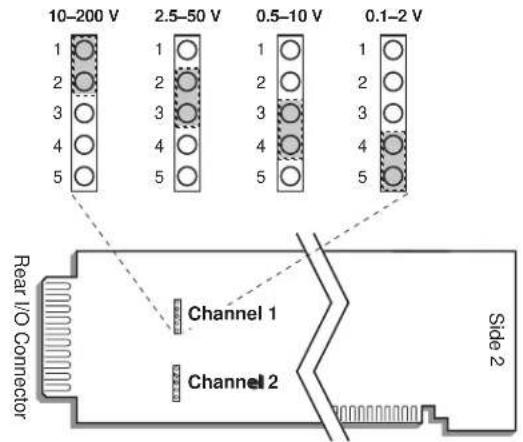
- Position the jumper for each channel as shown in Fig. 5 to set the desired voltage range for that channel. NOTE THAT ALL RANGES ARE PROTECTED AGAINST AN OVERLOAD OF UP TO 200 V.
- Keep out the 10A41-2C card for the filter selection procedure, below.
3.b SELECTING FILTER BANDWIDTH
Every 10A41-2C card is preset, at the factory, for the lowest filter bandwidth (1.25 Hz). While yielding the slowest response, this setting also provides the widest dynamic range. If a faster response is more important than dynamic range, you may select one of three higher bandwidth values (2.5 Hz, 5 Hz, or 12.8 Hz) for a 10A41-2C's Channel No. "x," as follows:
- Locate the FILTER BANDWIDTH JUMPER PINS on the 10A41-2C board (see Fig. 6, below). One "minijumper" is provided for each channel, for interconnecting any two adjacent jumper pins.
- Position the jumper for each channel as shown in Fig. 6 to set the desired filter bandwidth for that channel.
- Reinsert the 10A41-2C in its mainframe slot.
- TURN OFF THE SYSTEM MAINFRAME. Short both the +SIGNAL and -SIGNAL pins for Channel No. x to POWER COMMON (Pin/Terminal 5 or 10).
- Reactivate mainframe power.
- You must now "zero" the channel. Run the Configurator Software and select Calibrate... from the File menu. Then, via the On-Line Calibration window, enter a ZERO calibration point of "0" for Channel No. x (see Manual Section 3.e.6 for general instructions).
- Turn OFF the system mainframe once more, reconnect the +SIGNAL and -SIGNAL pins to the channel's normal frequency source (see cabling, above), and reactivate mainframe power.
IMPORTANT: WHENEVER YOU CHANGE THE FILTER BANDWIDTH FOR A 10A41-2C CHANNEL, YOU MUST PERFORM STEPS 4 THROUGH 7, ABOVE.

3.c CONFIGURATION AND CALIBRATION
For initial configuration of ANALOG INPUT CHANNELS dedicated to a specific Model 10A41-2C card when used in SPS6000, see Manual Sections 3.a and 3.b.
CALCULATED CALIBRATION
In an SPS6000 system, a nominally accurate CALCULATED CALIBRATION should be initially applied to every Model 10A41-2C channel, even if you intend to perform additional "two-point" calibration (see Manual Sections 3.b and 3.e.5 for a general discussion of this calibration technique). To do so, you will enter an appropriate value for each of the following parameters in the channel's Input Configuration window:
- FILTERS: This setting is fixed at a cutoff frequency of 2.00 Hz for every 10A41-2C channel, and cannot be changed.
- APPLICATION: Select FLOW, FREQUENCY, or RPM from the popup list, depending on the parameter to be measured by this channel.
NOTE: Regardless of the "APPLICATION" you select, the "Transducer Information" and/or "Output Information" numbers you enter will be automatically set to the highest precision that is presently displayable by the system, based on the currently entered full-scale transducer range and the system's full scale of "32767" for display A/D conversion.
Also note that the Configurator Software will display an appropriate error message if you try to enter a "Transducer" or "Output" value that is incompatible with one or more existing calibration settings. For example, it will not let you specify too much (or too little) input signal for the presently specified transducer full-scale range—or an output offset that lies outside the range allowed by previously entered calibration values.
IF YOUR SELECTED APPLICATION IS "FLOW"—
- UNITS: Select from the popup list the desired volume units to be used in the expression of this channel's volumetric flow measurement.
- PULSES PER [selected volume units]: Select from the popup list the desired time (or "rate") units to be used in the expression of this channel's volumetric flow measurement (Hr, Min, or Sec).
TRANSDUCER INFORMATION:
- FULL SCALE FLOW: Enter here the full-scale rating of the 10A41-2C channel's source transducer, expressed in the selected units of volumetric flow, as specified by the transducer manufacturer.
- FLOWMETER K FACTOR: Enter here the "K Factor" of the 10A41-2C channel's source transducer, expressed as pulses per selected units of volumetric flow, as specified by the transducer manufacturer.
OUTPUT INFORMATION:
- FULL SCALE OUTPUT ([volume units] / [rate units]): Enter here the desired full-scale measurement (to be represented by a full-scale analog output of 10 V-DC), expressed in the selected units of volumetric flow.
- OFFSET (RESIDUAL, [volume units] / [rate units]): Enter here the desired zero offset to be applied to the 10A41-2C channel's measurement reading,
expressed in the selected units of volumetric flow. Enter a number here to offset any residual flow indication when the actual flow is known to be zero.
IF YOUR SELECTED APPLICATION IS "FREQUENCY"—
the Input Configuration window will only request the relevant "Output Information":
OUTPUT INFORMATION:
- FULL SCALE FREQUENCY (IN HZ): Enter here the desired full-scale measurement (to be represented by a full-scale analog output of 10 V-DC), expressed in hertz.
- OFFSET (IN HZ): Enter here the desired zero offset to be applied to the 10A41-2C channel's measurement reading, expressed in hertz.
IF YOUR SELECTED APPLICATION IS "RPM"—
RPM CALIBRATION INFORMATION:
- PULSES PER REVOLUTION: Enter here the maximum pulses per revolution developed by the 10A41-2C channel's source transducer, as specified by the transducer manufacturer.
OUTPUT INFORMATION:
- FULL SCALE OUTPUT (IN RPM): Enter here the desired full-scale measurement (to be represented by a full-scale analog output of 10 V-DC), expressed in RPM.
- OFFSET (RESIDUAL, IN RPM): Enter here the desired zero offset to be applied to the 10A41-2C channel's measurement reading, expressed RPM. Enter a number here to offset any residual RPM indication when the actual RPM is known to be zero.
Remember that CALCULATED CALIBRATION will not go into effect until the configuration that contains the user-entered calibration values is downloaded to the SPS6000 system via the procedure given in Manual Section 3.c.4.
Two-Point (Deadweight) Calibration
If a 10A41-2C channel's initial software-calculated calibration does not yield sufficient accuracy—and if the channel's received frequency input is an analog of another parameter (such as Gallons Per Minute) which has one or more independently and accurately known calibration values—additional calibration can be performed on a real-time basis, using the Configurator Software's On-Line Calibration window or the system's front-panel display/keypad. Manual Section 3.e.6 gives general instructions for this conventional "zero and span" calibration technique. Although two-point calibration is usually performed only when "FLOW" or "RPM" is selected for APPLICATION in a 10A41-2C channel's Input Configuration window, it can also be used to improve the CALCULATED calibration of an input that measures frequency itself (beyond the 10A41-2C card's inherent limit of ±0.05% of full scale).
If you want to permanently save the scaling and offset values established during deadweight calibration, be sure to apply a SAVE ONLINE CHANGES command as soon as calibration is complete (see Manual Section 3.e.4).
NOTE: Calibrated Flowmeter K Factor and Calibrated Offset (Residual) values are displayed in a 10A41-2C channel's Input Configuration window. Initially, these
“calibrated” values will be the same as the last user-entered Flowmeter K Factor and Offset (Residual) values to have been downloaded to the SPS6000. However, as soon as a “zero” calibration point is entered during on-line calibration of this channel, the “calibrated” zero offset of the output signal is automatically determined and applied by the system. As soon as a “span” calibration point is entered during on-line calibration, the “calibrated” electrical output of the source transducer is automatically determined and applied, in order to achieve the desired scaling. The displayed Calibrated Flowmeter K Factor then represents the actual value of full-scale transducer output (in electrical units) currently in effect within the SPS6000 system, while the displayed Calibrated Offset (Residual) represents the actual output offset currently in effect, in the appropriate engineering units. For a properly calibrated channel, there should be little difference between the actual “calibrated” K-factor/offset values and the respective stored values—i.e., the last user-entered K-factor/offset values to have been downloaded to the SPS6000. Ideally, the two values should be equal.
WITH OPTIONAL CONNECTOR
FOR FULL COMPLIANCE WITH

STANDARDS WHEN USED IN AN SPS6000 SYSTEM
MODEL 10A60-4
QUAD VOLTAGE
CONDITIONER CARD
1 GENERAL DESCRIPTION AND SPECIFICATIONS
The Model 10A60-4 is a general-purpose conditioner allowing input of up to four external voltage signals. Mixed as desired, these may originate from DC-to-DC LVDT's, potentiometer-type sensors, and other 2-wire analog signal sources that provide their own power supply. Or they may represent the outputs of other instrument systems having various voltage levels and grounding configurations.
Inputs can be either floating (differential) or grounded (single-ended). With differential inputs, generous common-mode range and excellent common-mode rejection eliminate ground-coupling errors and other problems normally associated with off-ground signal sources. Chopper-stabilized DC amplification with active low-pass filtering yields smooth and stable measurement of the true average value of the input variable, even in the face of substantial dynamic content.
ADDITIONAL 10A60-4 SPECIFICATIONS
Transducer Types: 2-wire DC voltage sources, grounded or floating
Input Voltage Ranges: ±0.5, 1.0, 2.0, 5.0, 10, or 20 V-DC; automatically selected—on an individual channel basis—when the channel is configured; for "type" codes assigned to 10A60-4 data channels, see Appendix A of the latest Daytronic Conditioner Cards Catalog
Amplifier (per channel):
Normal-Mode Range: ±20 V operating; ±200 V without instrument damage
Common-Mode Range: ±50 V operating; ±300 V without instrument damage
Common-Mode Rejection Ratio: DC: -60 dB; at 60 Hz: -70 dB
Input Impedance: Differential: 2 MΩ; Common-Mode: 0.5 MΩ
Offset: Initial: ±0.5 mV; vs. Temperature: ±0.005 mV/°C; vs. Time: ±0.05 mV/month
Gain Accuracy: ±0.02% of full scale typical, following calibration*
Gain Stability: vs. Temperature: ±50 ppm/°C; vs. Time: ±50 ppm/month
Filter (per channel): 3-pole modified Butterworth; 3 dB down at 10 Hz; 60 dB down at 100 Hz
Step-Response Settling Time (Full-Scale Output):
To 1% of final value: 150 msec
To 0.1% of final value: 200 msec
To 0.02% of final value: 250 msec
Auxiliary Outputs: Filtered outputs available as input to an Analog Signal Processor Card
* Initial (uncalibrated) inaccuracy may be as great as ±1.5% of full scale. Maximum error that could occur upon replacement of a Model 10A60-4 not followed by calibration is ±3% of full scale.
2 TRANSDUCER CONNECTIONS
IMPORTANT
The type of I/O CONNECTOR to be used with the Model 10A60-4 will depend on whether or not you wish your SPS6000 system to comply with CE standards.
If CE compliance is NOT required, you may use the "conventional" connector that comes with the 10A60-4 card. If CE compliance is required, you MUST use the Model C48-CE Conditioner Connector, which is ordered separately from the 10A60-4 card. Both "conventional" and "CE-compliant" connectors are fully described in Manual Section 2.b.3.
ALSO NOTE: CE COMPLIANCE FURTHER REQUIRES THE CABLE SHIELDING SHOWN IN FIG. 2(a) OR 2(b). For more information on the “CONNECTION OF CABLE SHIELD,” see Manual Section 2.b.3.
Cabling for floating inputs is given in Fig. 1(a) for "conventional" cabling using the standard Daytronic 60322 connector, and in Fig. 2(a) for CE-compliant cabling using the Model C48-CE. NOTE: To minimize signal noise, it is recommended that for a floating (ungrounded) input with high common-mode impedance, the COMMON pin or terminal be tied to the -SIGNAL line at the connector.
Cabling for grounded inputs is given in Fig. 1(b) for “conventional” cabling using the 60322 connector, and in Fig. 2(b) for CE-compliant cabling using the C48-CE.
Table 1 gives standard pin or terminal assignments for the 10A60-4 I/O connector (“conventional” or “CE-compliant,” respectively).
Table 1 Model 10A60-4 Pin/Terminal Assignments
| I/O Connector Conditioner Conditioner Pin/Terminal Channel Line Number Number Function | |
| 1 1 +SIGNAL | |
| A 1 -SIGNAL | |
| 2 1 COMMON | |
| B | Not Committed |
| 3 2 +SIGNAL | |
| C 2 -SIGNAL | |
| 4 2 COMMON | |
| D | Not Committed |
| 5 3 +SIGNAL | |
| E 3 -SIGNAL | |
| 6 3 COMMON | |
| F | Not Committed |
| 7 4 +SIGNAL | |
| H 4 -SIGNAL | |
| 8 4 COMMON | |
| J | Not Committed |
| 9,K,10,L | Not Committed |
Fig. 1 Model 10A60-4 "CONVENTIONAL" Transducer Cabling

flowchart
graph TD
    A["Reg. Power Supply (if required)"] --> B["Analog Signal Source"]
    B --> C["+SIGNAL"]
    B --> D["-SIGNAL"]
    C --> E["CONDITIONER CONNECTOR (No. 60322)"]
    D --> E
    E --> F["SHIELD"]
    F --> G["Ground Lug"]
    style A fill:#f9f,stroke:#333
    style B fill:#ccf,stroke:#333
    style E fill:#cfc,stroke:#333
    style F fill:#fcc,stroke:#333
    style G fill:#ffc,stroke:#333
Fig. 1(a) 2-Wire Differential (Floating) Voltage Input

Fig. 2 Model 10A60-4 CE-COMPLIANT Transducer Cabling

flowchart
graph LR
    A["Reg. Power Supply (if required)"] --> B["Analog Signal Source"]
    B --> C["+SIGNAL"]
    B --> D["-SIGNAL"]
    C --> E["Model C48-CE CONDITIONER CONNECTOR"]
    D --> E
    E --> F["Channel 4: COMMON* -SIGNAL +SIGNAL"]
    E --> G["Channel 3: COMMON* -SIGNAL +SIGNAL"]
    E --> H["SHIELD SHIELD SHIELD"]
    E --> I["SHIELD SHIELD SHIELD"]
    E --> J["SHIELD SHIELD SHIELD"]
    E --> K["SHIELD SHIELD SHIELD"]
    E --> L["SHIELD SHIELD SHIELD"]
    E --> M["SHIELD SHIELD SHIELD"]
    E --> N["SHIELD SHIELD SHIELD"]
    E --> O["SHIELD SHIELD SHIELD"]
    E --> P["SHIELD SHIELD SHIELD"]
    E --> Q["SHIELD SHIELD SHIELD"]
    E --> R["SHIELD SHIELD SHIELD"]
    E --> S["SHIELD SHIELD SHIELD"]
    E --> T["SHIELD SHIELD SHIELD"]
    E --> U["SHIELD SHIELD SHIELD"]
    E --> V["SHIELD SHIELD SHIELD"]
    E --> W["SHIELD SHIELD SHIELD"]
    E --> X["SHIELD SHIELD SHIELD"]
    E --> Y["SHIELD SHIELD SHIELD"]
    E --> Z["SHIELD SHIELD SHIELD"]
    E --> AA["SHIELD SHIELD SHIELD"]
    E --> AB["SHIELD SHIELD SHIELD"]
    E --> AC["SHIELD SHIELD SHIELD"]
    E --> AD["SHIELD SHIELD SHIELD"]
    E --> AE["SHIELD SHIELD SHIELD"]
    E --> AF["SHIELD SHIELD SHIELD"]
    E --> AG["SHIELD SHIELD SHIELD"]
    E --> AH["SHIELD SHIELD SHIELD"]
    E --> AI["SHIELD SHIELD SHIELD"]
    E --> AJ["SHIELD SHIELD SHIELD"]
    E --> AK["SHIELD SHIELD SHIELD"]
    E --> AL["SHIELD SHIELD SHIELD"]
    E --> AM["SHIELD SHIELD SHIELD"]
    E --> AN["SHIELD SHIELD SHIELD"]
    E --> AO["SHIELD SHIELD SHIELD"]
    E --> AP["SHIELD SHIELD SHIELD"]
    E --> AQ["SHIELD SHIELD SHIELD"]
    E --> AR["SHIELD SHIELD SHIELD"]
    E --> AS["SHIELD SHIELD SHIELD"]
    E --> AT["SHIELD SHIELD SHIELD"]
    E --> AU["SHIELD SHIELD SHIELD"]
    E --> AV["SHIELD SHIELD SHIELD"]
    E --> AW["SHIELD SHIELD SHIELD"]
    E --> AX["SHIELD SHIELD SHIELD"]
    E --> AY["SHIELD SHIELD SHIELD"]
    E --> AZ["SHIELD SHIELD SHIELD"]
    E --> BA["SHIELD SHIELD SHIELD"]
    E --> BB["SHIELD SHIELD SHIELD"]
    E --> BC["SHIELD SHIELD SHIELD"]
    E --> BD["SHIELD SHIELD SHIELD"]
    E --> BE["SHIELD SHIELD SHIELD"]
    E --> BF["SHIELD SHIELD SHIELD"]
    E --> BG["SHIELD SHIELD SHIELD"]
    E --> BH["SHIELD SHIELD SHIELD"]
    E --> BI["SHIELD SHIELD SHIELD"]
    E --> BJ["SHIELD SHIELD SHIELD"]
    E --> BK["SHIELD SHIELD SHIELD"]
    E --> BL["SHIELD SHIELD SHIELD"]
    E --> BM["SHIELD SHIELD SHIELD"]
    E --> BN["SHIELD SHIELD SHIELD"]
    E --> BO["SHIELD SHIELD SHIELD"]
    E --> BP["SHIELD SHIELD SHIELD"]
    E --> BQ["SHIELD SHIELD SHIELD"]
    E --> BR["SHIELD SHIELD SHIELD"]
    E --> BS["SHIELD SHIELD SHIELD"]
    E --> BT["SHIELD SHIELD SHIELD"]
    E --> BU["SHIELD SHIELD SHIELD"]
    E --> BV["SHIELD SHIELD SHIELD"]
    E --> BW["SHIELD SHIELD SHIELD"]

flowchart
graph LR
    A["Reg. Power Supply (if required)"] --> B["Analog Signal Source"]
    B --> C["+SIGNAL"]
    B --> D["-SIGNAL"]
    C --> E["Model C48-CE CONDITIONER CONNECTOR"]
    D --> E
    E --> F["Channel 4: -SIGNAL +SIGNAL"]
    E --> G["Channel 3: -SIGNAL +SIGNAL"]
    E --> H["SHIELD SHIELD SHIELD"]
    E --> I["SHIELD SHIELD SHIELD"]
    E --> J["SHIELD SHIELD SHIELD"]
    E --> K["SHIELD SHIELD SHIELD"]
    E --> L["SHIELD SHIELD SHIELD"]
    E --> M["SHIELD SHIELD SHIELD"]
    E --> N["SHIELD SHIELD SHIELD"]
    E --> O["SHIELD SHIELD SHIELD"]
    E --> P["SHIELD SHIELD SHIELD"]
    E --> Q["SHIELD SHIELD SHIELD"]
    E --> R["SHIELD SHIELD SHIELD"]
    E --> S["SHIELD SHIELD SHIELD"]
    E --> T["SHIELD SHIELD SHIELD"]
    E --> U["SHIELD SHIELD SHIELD"]
    E --> V["SHIELD SHIELD SHIELD"]
    E --> W["SHIELD SHIELD SHIELD"]
    E --> X["SHIELD SHIELD SHIELD"]
    E --> Y["SHIELD SHIELD SHIELD"]
    E --> Z["SHIELD SHIELD SHIELD"]
    E --> AA["SHIELD SHIELD SHIELD"]
    E --> AB["SHIELD SHIELD SHIELD"]
    E --> AC["SHIELD SHIELD SHIELD"]
    E --> AD["SHIELD SHIELD SHIELD"]
    E --> AE["SHIELD SHIELD SHIELD"]
    E --> AF["SHIELD SHIELD SHIELD"]
    E --> AG["SHIELD SHIELD SHIELD"]
    E --> AH["SHIELD SHIELD SHIELD"]
    E --> AI["SHIELD SHIELD SHIELD"]
    E --> AJ["SHIELD SHIELD SHIELD"]
    E --> AK["SHIELD SHIELD SHIELD"]
    E --> AL["SHIELD SHIELD SHIELD"]
    E --> AM["SHIELD SHIELD SHIELD"]
    E --> AN["SHIELD SHIELD SHIELD"]
    E --> AO["SHIELD SHIELD SHIELD"]
    E --> AP["SHIELD SHIELD SHIELD"]
    E --> AQ["SHIELD SHIELD SHIELD"]
    E --> AR["SHIELD SHIELD SHIELD"]
    E --> AS["SHIELD SHIELD SHIELD"]
    E --> AT["SHIELD SHIELD SHIELD"]
    E --> AU["SHIELD SHIELD SHIELD"]
    E --> AV["SHIELD SHIELD SHIELD"]
    E --> AW["SHIELD SHIELD SHIELD"]
    E --> AX["SHIELD SHIELD SHIELD"]
    E --> AY["SHIELD SHIELD SHIELD"]
    E --> AZ["SHIELD SHIELD SHIELD"]
    E --> BA["SHIELD SHIELD SHIELD"]
    E --> BB["SHIELD SHIELD SHIELD"]
    E --> BC["SHIELD SHIELD SHIELD"]
    E --> BD["SHIELD SHIELD SHIELD"]
    E --> BE["SHIELD SHIELD SHIELD"]
    E --> BF["SHIELD SHIELD SHIELD"]
    E --> BG["SHIELD SHIELD SHIELD"]
    E --> BH["SHIELD SHIELD SHIELD"]
    E --> BI["SHIELD SHIELD SHIELD"]
    E --> BJ["SHIELD SHIELD SHIELD"]
    E --> BK["SHIELD SHIELD SHIELD"]
    E --> BL["SHIELD SHIELD SHIELD"]
    E --> BM["SHIELD SHIELD SHIELD"]
    E --> BN["SHIELD SHIELD SHIELD"]
    E --> BO["SHIELD SHIELD SHIELD"]
    E --> BP["SHIELD SHIELD SHIELD"]
    E --> BQ["SHIELD SHIELD SHIELD"]
    E --> BR["SHIELD SHIELD SHIELD"]
    E --> BS["SHIELD SHIELD SHIELD"]
    E --> BT["SHIELD SHIELD SHIELD"]
    E --> BU["SHIELD SHIELD SHIELD"]
    E --> BV["SHIELD SHIELD SHIELD"]
    E --> BW["SHIELD SHIELD SHIELD"]
SETUP AND/OR OPERATING CONSIDERATIONS
3.a CONFIGURATION AND CALIBRATION
For initial configuration of ANALOG INPUT CHANNELS dedicated to a specific Model 10A60-4 card when used in SPS6000, see Manual Sections 3.a and 3.b.
CALCULATED CALIBRATION
In an SPS6000 system, a nominally accurate CALCULATED CALIBRATION should be initially applied to every Model 10A60-4 channel, even if you intend to perform additional "two-point" calibration (see Manual Sections 3.b and 3.e.5 for a general discussion of this calibration technique). To do so, you will enter an appropriate value for each of the following parameters in the channel's Input Configuration window:
- FILTERS: This setting is fixed at a cutoff frequency of 10.00 Hz for every 10A60-4 channel, and cannot be changed.
- APPLICATION: Select TRANSDUCER from the popup list if the received input is to represent an analog of some parameter other than voltage; select VOLTAGE if the input is to represent voltage itself.
NOTE: Regardless of the “APPLICATION” you select, the “Transducer Information” and/or “Output Information” numbers you enter will be automatically set to the highest precision that is presently displayable by the system, based on the currently entered full-scale transducer range and the system’s full scale of “32767” for display A/D conversion.
Also note that the Configurator Software will display an appropriate error message if you try to enter a "Transducer" or "Output" value that is incompatible with one or more existing calibration settings. For example, it will not let you specify too much (or too little) input signal for the presently specified transducer full-scale range—or an output offset that lies outside the range allowed by previously entered calibration values.
IF YOUR SELECTED APPLICATION IS "TRANSDUCER"—
- DESC: Enter here the desired engineering units in which the 10A60-4 channel's final measurement value is to be expressed, as an alphanumeric string of up to four characters.
TRANSDUCER INFORMATION:
- FULL SCALE RANGE: Enter here the full-scale rating of the 10A60-4 channel's source transducer, expressed in the engineering units entered in the DESC field, as specified by the transducer manufacturer. NOTE: If you attempt to enter a value of full-scale range that yields either not enough or too much input signal for the card type, the software will ask you whether you want the transducer full-scale range and the full-scale output to be set equal (you may answer Ok or Cancel).
- FULL SCALE OUTPUT (ELECTRICAL UNITS): Enter here the full-scale output of the 10A60-4 channel's source transducer, expressed in VOLTS, as specified by the transducer manufacturer.
OUTPUT INFORMATION:
- FULL SCALE OUTPUT (IN [specified units]): Enter here the desired full-scale measurement (to be represented by a full-scale analog output of 10 V-DC), expressed in the engineering units entered in the DESC field.
- OFFSET (IN [specified units]): Enter here the desired zero offset to be applied to the 10A60-4 channel's measurement reading, expressed in the engineering units entered in the DESC field.
IF YOUR SELECTED APPLICATION IS "VOLTAGE"—
the Input Configuration window will only request the relevant "Output Information":
OUTPUT INFORMATION:
- FULL SCALE RANGE: Enter here the desired full-scale measurement (to be represented by a full-scale analog output of 10 V-DC), expressed in VOLTS.
- OFFSET: Enter here the desired zero offset to be applied to the 10A60-4 channel's measurement reading, expressed in VOLTS.
Remember that CALCULATED CALIBRATION will not go into effect until the configuration that contains the user-entered calibration values is downloaded to the SPS6000 system via the procedure given in Manual Section 3.c.4.
Two-Point (Deadweight) Calibration
If a 10A60-4 channel's initial software-calculated calibration does not yield sufficient accuracy—and if the channel's received voltage input is an analog of another parameter which has one or more independently and accurately known calibration values, additional calibration can be performed on a real-time basis, using the Configurator Software's On-Line Calibration window or the system's front-panel display/keypad. Manual Section 3.e.6 gives general instructions for this conventional "zero and span" calibration technique. Although two-point calibration is usually performed only when "TRANSDUCER" is selected for APPLICATION in a 10A60-4 channel's Input Configuration window, it can also be used to improve the CALCULATED calibration of an input that measures voltage itself (beyond the 10A60-4 card's inherent limit of ±0.5 mV or ±0.02% of full scale, whichever represents the greater error).
If you want to permanently save the scaling and offset values established during deadweight calibration, be sure to apply a SAVE ONLINE CHANGES command as soon as calibration is complete (see Manual Section 3.e.4).
NOTE: Calibrated Full Scale Output (Electrical Units) and Calibrated Offset values are displayed in a 10A60-4 channel's Input Configuration window. Initially, these "calibrated" values will be the same as the last user-entered Full Scale Output and Offset values to have been downloaded to the SPS6000. However, as soon as a "zero" calibration point is entered during on-line calibration of this channel, the "calibrated" zero offset of the output signal is automatically determined and applied by the system. As soon as a "span" calibration point is entered during on-line calibration, the "calibrated" electrical output of the source transducer is automatically determined and applied, in order to achieve the desired scaling. The displayed Calibrated Full Scale Output then represents the actual value of full-scale transducer output (in electrical units) currently in effect within the SPS6000 system, while the displayed Calibrated Offset represents the actual output offset currently in effect, in the specified engineering units. For a properly calibrated channel, there should be little difference between the actual "calibrated" output/offset values and the respective stored values—i.e., the last user-entered output/offset values to have been downloaded to the SPS6000. Ideally, the two values should be equal.
WITH OPTIONAL CONNECTOR
FOR FULL COMPLIANCE WITH

STANDARDS WHEN USED IN
AN SPS6000 SYSTEM
MODEL 10A61-2
DUAL 4-20 MA
CONDITIONER CARD
1 GENERAL DESCRIPTION AND SPECIFICATIONS
The Model 10A61-2 accepts one or two independent current signals within the ISA standard range of 4-20 mA. Both unipolar and bipolar (“zero-center”) inputs are allowed. Since the 10A61-2 does not provide excitation, the current source must supply its own power supply, if required.
Chopper-stabilized amplification with active low-pass filtering yields excellent voltage compliance and make the 10A61-2 suitable for virtually any standard Process Industry current input.
ADDITIONAL 10A61-2 SPECIFICATIONS
Input Current: 4 to 20 mA (unipolar) or 4 to 12 to 20 mA (bipolar or "zero-center"); automatically selected—on an individual channel basis—when the channel is configured; for "type" codes assigned to 10A61-2 data channels, see Appendix A of the latest Daytronic Conditioner Cards Catalog
Amplifier (per channel):
Common-Mode Range: ±50 V operating; ±90 V without instrument damage
Common-Mode Rejection Ratio: DC: -60 dB; at 60 Hz: -75 dB
Input Impedance: Differential: 100 Ω; Common-Mode: 125 kΩ
Burden: 2 V-DC at full scale
Offset: Initial: ±0.05% of full scale; vs. Temperature: ±50 ppm/°C; vs. Time: ±20 ppm/month
Gain Accuracy: ±0.02% of full scale typical, following calibration*
Gain Stability: vs. Temperature: ±50 ppm/°C; vs. Time: ±50 ppm/month
Filter (per channel): 3-pole modified Butterworth; 3 dB down at 10 Hz; 60 dB down at 100 Hz
Step-Response Settling Time (Full-Scale Output):
To 1% of final value: 150 msec
To 0.1% of final value: 200 msec
To 0.02% of final value: 250 msec
Auxiliary Outputs: Filtered outputs available as input to an Analog Signal Processor Card
* Initial (uncalibrated) inaccuracy may be as great as ±0.05% of full scale. Maximum error that could occur upon replacement of a Model 10A61-2 not followed by calibration is ±0.1% of full scale.
2 TRANSDUCER CONNECTIONS
IMPORTANT
The type of I/O CONNECTOR to be used with the Model 10A61-2 will depend on whether or not you wish your SPS6000 system to comply with CE standards.
If CE compliance is NOT required, you may use the "conventional" connector that comes with the 10A61-2 card. If CE compliance is required, you MUST use the Model C12-CE Conditioner Connector, which is ordered separately from the 10A61-2 card. Both "conventional" and "CE-compliant" connectors are fully described in Manual Section 2.b.3.
ALSO NOTE: CE COMPLIANCE FURTHER REQUIRES THE CABLE SHIELDING SHOWN IN FIG. 2. For more information on the "CONNECTION OF CABLE SHIELD," see Manual Section 2.b.3
"Conventional" cabling using the standard Daytronic 60322 connector is given in Fig. 1; CE-compliant cabling using the Model C12-CE, in Fig. 2.
Table 1 gives standard pin or terminal assignments for the 10A61-2 I/O connector (“conventional” or “CE-compliant,” respectively).
Fig. 1 Model 10A61-2 "CONVENTIONAL" Transducer Cabling

flowchart
graph TD
    A["Reg. Power Supply (if required)"] --> B["4-20 mA Source"]
    B --> C["+SIGNAL"]
    B --> D["-SIGNAL"]
    C --> E["CONDITIONER CONNECTOR (No. 60322)"]
    D --> E
    E --> F["SHIELD"]
    F --> G["Ground Lug"]
    H["Connector pins shown as viewed from rear (cable) side of connector"] --> I["+TEST*"]
    H --> J["-TEST*"]
    I --> K["A 1"]
    I --> L["B 2"]
    I --> M["C 3"]
    I --> N["D 4"]
    I --> O["E 5"]
    I --> P["F 6"]
    I --> Q["H 7"]
    I --> R["J 8"]
    I --> S["K 9"]
    I --> T["L 10"]
    U["* For factory use only."] --> F
Table 1 Model 10A61-2 Pin/Terminal Assignments
I/O Connector Conditioner Conditioner Pin/Terminal Channel Line Number Number Function
| 1 1 +TEST* | |
| A 1 -TEST* | |
| 2 1 +SIGNAL | |
| B 1 | -SIGNAL |
| 3 1 +SIGNAL | |
| C 1 | -SIGNAL |
51 COMMON
4,D,E Not Committed
62+TEST*
F 2 -TEST*
7 2 + SIGNAL
H 2 - SIGNAL
8 2 + SIGNAL
J 2 - SIGNAL
10 2 COMMON
9,K,L Not Committed
* For factory use only.
Fig. 2 Model 10A61-2 CE-COMPLIANT Transducer Cabling

flowchart
graph LR
    A["Reg. Power Supply (if required)"] --> B["4-20 mA Source"]
    B --> C["+SIGNAL"]
    B --> D["-SIGNAL"]
    C --> E["Model C12-CE CONDITIONER CONNECTOR"]
    D --> E
    E --> F["Channel 2: -SIGNAL"]
    E --> G["+SIGNAL"]
    H["+TEST*"] --> E
    I["-TEST*"] --> E
    J["SHIELD"] --> E
    K["A"] --> E
    L["A"] --> E
    M["A"] --> E
    N["A"] --> E
    O["A"] --> E
    P["A"] --> E
    Q["B"] --> E
    R["B"] --> E
    S["B"] --> E
    T["B"] --> E
    U["C"] --> E
    V["C"] --> E
    W["C"] --> E
    X["C"] --> E
    Y["C"] --> E
    Z["D"] --> E
    AA["D"] --> E
    AB["E"] --> E
    AC["E"] --> E
    AD["E"] --> E
    AE["E"] --> E
    AF["E"] --> E
    AG["E"] --> E
    AH["E"] --> E
    AI["E"] --> E
    AJ["E"] --> E
    AK["E"] --> E
    AL["E"] --> E
    AM["E"] --> E
    AN["E"] --> E
    AO["E"] --> E
    AP["E"] --> E
    AQ["E"] --> E
    AR["E"] --> E
    AS["E"] --> E
    AT["E"] --> E
    AU["E"] --> E
    AV["E"] --> E
    AW["E"] --> E
    AX["E"] --> E
    AY["E"] --> X
    AZ["E"] --> Y
    BA["E"] --> Z
* For factory use only.
3 SETUP AND/OR OPERATING CONSIDERATIONS
3.a CONFIGURATION AND CALIBRATION
For initial configuration of ANALOG INPUT CHANNELS dedicated to a specific Model 10A61-2 card when used in SPS6000, see Manual Sections 3.a and 3.b.
CALCULATED CALIBRATION
In an SPS6000 system, a nominally accurate CALCULATED CALIBRATION should be initially applied to every Model 10A61-2 channel, even if you intend to perform additional "two-point" calibration (see Manual Sections 3.b and 3.e.5 for a general discussion of this calibration technique). To do so, you will enter an appropriate value for each of the following parameters in the channel's Input Configuration window:
- FILTERS: This setting is fixed at a cutoff frequency of 10.00 Hz for every 10A61-2 channel, and cannot be changed.
- APPLICATION: Select either 4-12-20 mA Bipolar Transducer or 4-20 mA Unipolar Transducer from the popup list, depending on the nature of the current input source.
- DESC: Enter the desired engineering units in which the 10A61-2 channel's final measurement value is to be expressed, as an alphanumeric string of up to four characters.
NOTE: Regardless of the "APPLICATION" you select, the "Transducer Information" and/or "Output Information" numbers you enter will be automatically set to the highest precision that is presently displayable by the system, based on the currently entered full-scale transducer range and the system's full scale of "32767" for display A/D conversion.
Also note that the Configurator Software will display an appropriate error message if you try to enter a "Transducer" or "Output" value that is incompatible with one or more existing calibration settings. For example, it will not let you specify too much (or too little) input signal for the presently specified transducer full-scale range—or an output offset that lies outside the range allowed by previously entered calibration values.
TRANSDUCER INFORMATION:
- FULL SCALE RANGE (@ 20 MA IN ENG. UNITS): Enter here the full-scale rating of the 10A61-2 channel's source transducer, expressed in the engineering units entered in the DESC field, as specified by the transducer manufacturer. NOTE: If you attempt to enter a value of full-scale range that yields either not enough or too much input signal for the card type, the software will ask you whether you want the transducer full-scale range and the full-scale output to be set equal (you may answer Ok or Cancel).
NOTE: You will not enter anything for the transducer's ZERO POINT VALUE. The Configurator here reminds you that this value is either at 12 mA (if Bipolar Transducer was chosen) or at 4 mA (if Unipolar Transducer was chosen).
OUTPUT INFORMATION:
- FULL SCALE OUTPUT ([specified units]): Enter here the desired full-scale measurement (to be represented by a full-scale analog output of 10 V-DC), expressed in the engineering units entered in the DESC field.
- OFFSET ([specified units]): Enter here the desired zero offset to be applied to the 10A61-2 channel's measurement reading, expressed in the engineering units entered in the DESC field.
Remember that CALCULATED CALIBRATION will not go into effect until the configuration that contains the user-entered calibration values is downloaded to the SPS6000 system via the procedure given in Manual Section 3.c.4.
TWO-POINT (DEADWEIGHT) CALIBRATION
If a 10A61-2 channel's initial software-calculated calibration does not yield sufficient accuracy—and if the channel's received current input is an analog of another parameter which has one or more independently and accurately known calibration values, additional calibration can be performed on a real-time basis, using the Configurator Software's On-Line Calibration window or the system's front-panel display/keypad. Manual Section 3.e.6 gives general instructions for this conventional "zero and span" calibration technique. Two-point calibration can also be used to improve the CALCU-LATED calibration of an input that measures milliamperage itself (beyond the 10A61-2 card's inherent limit of ± 0.05% of full scale).
If you want to permanently save the scaling and offset values established during deadweight calibration, be sure to apply a SAVE ONLINE CHANGES command as soon as calibration is complete (see Manual Section 3.e.4).
NOTE: Calibrated Full Scale Range (@20 mA in Eng. Units) and Calibrated Offset values are displayed in a 10A61-2 channel's Input Configuration window. Initially, these "calibrated" values will be the same as the last user-entered Full Scale Range and Offset values to have been downloaded to the SPS6000. However, as soon as a "zero" calibration point is entered during on-line calibration of this channel, the "calibrated" zero offset of the output signal is automatically determined and applied by the system. As soon as a "span" calibration point is entered during on-line calibration, the "calibrated" electrical output of the source transducer is automatically determined and applied, in order to achieve the desired scaling. The displayed Calibrated Full Scale Range then represents the actual value of full-scale transducer output (in electrical units) currently in effect within the SPS6000 system, while the displayed Calibrated Offset represents the actual output offset currently in effect, in the specified engineering units. For a properly calibrated channel, there should be little difference between the actual "calibrated" range/offset values and the respective stored values—i.e., the last user-entered range/offset values to have been downloaded to the SPS6000. Ideally, the two values should be equal.

10A61-2 DUAL 4-20 MA CARD
WITH OPTIONAL CONNECTOR
FOR FULL COMPLIANCE WITH

STANDARDS WHEN USED IN AN SPS6000 SYSTEM
MODEL 10A63-2
DUAL VOLTAGE
CONDITIONER CARD
1 GENERAL DESCRIPTION AND SPECIFICATIONS
The Model 10A63-2 is a high-accuracy conditioner allowing input of one or two external voltage signals. Mixed as desired, these may originate from DC-to-DC LVDT's, potentiometer-type sensors, and other 2-, 3-, or 4-wire analog signal sources, either grounded or floating—or they may represent the outputs of other instrument systems having various voltage levels and grounding configurations.
The 10A63-2 offers a wide range of input voltages. Its differential inputs, generous common-mode range, and excellent common-mode rejection eliminate ground-coupling errors and other problems normally associated with off-ground signal sources. Nominal 5 V-DC excitation is provided for external sources that require it. "1/2 Bridge Completion" terminals allow "zero-center" operation of potentiometers with resistance from 1 to 10k .
ADDITIONAL 10A63-2 SPECIFICATIONS
Transducer Types: 2-, 3-, or 4-wire DC voltage sources, grounded or floating
Input Voltage Ranges: ±0.05, 0.1, 0.2, 0.5, 1, 2, 5, 10, 20, 50, 100, or 200 V-DC; automatically selected—on an individual channel basis—when the channel is configured; for “type” codes assigned to 10A63-2 data channels, see Appendix A of the latest Daytronic Conditioner Cards Catalog
Excitation (per channel): Nominal 5 V-DC; 50 mA, maximum
Amplifier (per channel):
Normal-Mode Range: ±200 V operating; ±500 V without instrument damage
Common-Mode Range: ±200 V operating; ±300 V without instrument damage
Common-Mode Rejection Ratio: DC: -120 dB; at 60 Hz: -60 dB
Input Impedance: Differential: 1 MΩ; Common-Mode: 0.5 MΩ
Offset: Initial: ±0.02% of full scale; vs. Temperature: ±50 ppm/°C; vs. Time: ±20 ppm/month
Gain Accuracy: ±0.02% of full scale typical, following calibration*
Gain Stability: vs. Temperature: ±50 ppm/°C; vs. Time: ±50 ppm/month (cont'd)
Filter (per channel): 3-pole modified Butterworth; 3 dB down at 5 Hz; 60 dB down at 100 Hz
Step-Response Settling Time (Full-Scale Output):
To 1% of final value: 200 msec
To 0.1% of final value: 300 msec
To 0.02% of final value: 400 msec
Auxiliary Outputs: Filtered outputs available as input to an Analog Signal Processor Card
2 TRANSDUCER CONNECTIONS
IMPORTANT
The type of I/O CONNECTOR to be used with the Model 10A63-2 will depend on whether or not you wish your SPS6000 system to comply with CE standards.
If CE compliance is NOT required, you may use the "conventional" connector that comes with the 10A63-2 card. If CE compliance is required, you MUST use the Model C10A63-CE Conditioner Connector, which is ordered separately from the 10A63-2 card. Both "conventional" and "CE-compliant" connectors are fully described in Manual Section 2.b.3.
ALSO NOTE: CE COMPLIANCE FURTHER REQUIRES THE CABLE SHIELDING SHOWN IN FIG. 2(a), 2(b), 2(c), or 2(d). For more information on the “CONNECTION OF CABLE SHIELD,” see Manual Section 2.b.3.
2-wire cabling for analog sources with no excitation from the 10A63-2 is given in Fig. 1(a) for "conventional" cabling using the standard Daytronic 60322 connector, and in Fig. 2(a) for CE-compliant cabling using the Model C10A63-CE. 3-wire zero-to-full-scale potentiometer cabling is given in Fig. 1(b) for "conventional" cabling using the 60322 connector, and in Fig. 2(b) for CE-compliant cabling using the C10A63-CE. 3-wire zero-center potentiometer cabling is given in Fig. 1(c) for "conventional" cabling using the 60322 connector, and in Fig. 2(c) for CE-compliant cabling using the C10A63-CE. Finally, 4-wire DC-to-DC LVDT cabling is given in Fig. 1(d) for "conventional" cabling using the 60322 connector, and in Fig. 2(d) for CE-compliant cabling using the C10A63-CE. Table 1 gives standard pin or terminal assignments for the 10A63-2 I/O connector ("conventional" or "CE-compliant," respectively).
With regard to both “conventional” and CE-compliant 10A63-2 cabling, note that floating (ungrounded) inputs are to be grounded at the site of the signal source, and not at the CONDITIONER CONNECTOR. Note also that the Model 10A63-2 has “1/2 BRIDGE COMPLETION” terminals to allow bipolar (“Zero Center”) operation of potentiometers. As shown in Figs. 1(c) and 2(c), the 1/2 BRIDGE is powered by the potentiometer excitation. Although this excitation is normally supplied by the 10A63-2—as shown in the figures—the user may replace it with his own precision source, if desired. In this case, Pins/Terminals 1 and A (for Channel 1) or Pins/Terminals 6 and F (for Channel 2) would not be used. The 1/2 BRIDGE terminals would tie into the user’s excitation lines (Pin/Terminal 2 or 7 to +EXCITATION; Pin/Terminal B or H to -EXCITATION).
Fig. 1 Model 10A63-2 "CONVENTIONAL" Transducer Cabling

Fig. 1(a) 2-Wire Cabling: No Excitation from 10A63-2

Fig. 1(b) 3-Wire Cabling: External Potentiometer, Zero to Full Scale

Fig. 1(c) 3-Wire Cabling: External Potentiometer, Zero Center

flowchart
graph TD
    A["DC-to-DC LVDT"] -->|+EXCITATION| B["Conditioner Connector (No. 60322)"]
    A -->|+SIGNAL| B
    A -->|-SIGNAL| B
    A -->|-EXCITATION| B
    B --> C["SHIELD"]
    C --> D["Connector pins shown as viewed from rear (cable) side of connector"]
    D --> E["Ground Lug"]
Table 1 Model 10A63-2 Pin/Terminal Assignments
| I/O Connector Conditioner ConditionerPin/Terminal Channel LineNumber Number Function | |
| 1 1 +EXCITATION (+5 V-DC) | |
| A 1 -EXCITATION (-5 V-DC) | |
| 2 1 1/2 BRIDGE (TO +EXC) | |
| B 1 1/2 BRIDGE (TO -EXC) | |
| 3 1 +SIGNAL | |
| C 1 -SIGNAL | |
| 4,D,5,E 1 Not Committed | |
| 6 2 +EXCITATION (+5 V-DC) | |
| F 2 -EXCITATION (-5 V-DC) | |
| 7 2 1/2 BRIDGE (TO +EXC) | |
| H 2 1/2 BRIDGE (TO -EXC) | |
| 8 2 +SIGNAL | |
| J 2 -SIGNAL | |
| 9,K,10,L | 2 Not Committed |
Fig. 2 Model 10A63-2 CE-COMPLIANT Transducer Cabling

flowchart
graph LR
    A["Reg. Power Supply (if required)"] --> B["Analog Signal Source"]
    B --> C["+SIGNAL"]
    B --> D["-SIGNAL"]
    B --> E["Add ground for floating inputs"]
    C --> F["Model C10A63-CE CONDITIONER CONNECTOR"]
    D --> F
    F --> G["SHIELD"]
    F --> H["Channel 2: -SIGNAL +SIGNAL"]
Fig. 2(b) 3-Wire Cabling: External Potentiometer, Zero to Full Scale

Fig. 2(c) 3-Wire Cabling: External Potentiometer, Zero Center

flowchart
graph LR
    A["Channel 1"] -->|+EXCITATION| B["Model C10A63-CE CONDITIONER CONNECTOR"]
    C["Channel 2: +SIGNAL"] -->|1/2 BRIDGE| B
    D["External Potentiometer, Tro Center"] --> E["+SIGNAL"]
    F["SHIELD"] --> G["BRIDGE"]
    H["1/2 BRIDGE"] --> I["BRIDGE"]
    J["5"] --> K["BRIDGE"]
    L["7"] --> M["BRIDGE"]
    N["9"] --> O["BRIDGE"]
    P["8"] --> Q["BRIDGE"]
    R["6"] --> S["BRIDGE"]
    T["-EXC."] --> U["BRIDGE"]
    V["+EXC."] --> W["BRIDGE"]
Fig. 2(d) 4-Wire Cabling: DC-to-DC LVDT Input

flowchart
graph LR
    A["DC-to-DC LVDT Input"] -->|+EXCITATION| B["Model C10A63-CE CONDITIONER CONNECTOR"]
    A -->|+SIGNAL| B
    A -->|-SIGNAL| B
    A -->|-EXCITATION| B
    B -->|1 L| C["SHIELD"]
    B -->|2 K| C
    B -->|3 J| C
    B -->|4 H| C
    B -->|5 F| C
    B -->|6 SHIELD| C
    C --> D["Channel 2: -SIGNAL +SIGNAL"]
    C --> E["-EXC. +EXC."]
3 SETUP AND/OR OPERATING CONSIDERATIONS
3.a CONFIGURATION AND CALIBRATION
For initial configuration of ANALOG INPUT CHANNELS dedicated to a specific Model 10A63-2 card when used in SPS6000, see Manual Sections 3.a and 3.b.
CALCULATED CALIBRATION
In an SPS6000 system, a nominally accurate CALCULATED CALIBRATION should be initially applied to every Model 10A63-2 channel, even if you intend to perform additional "two-point" calibration (see Manual Sections 3.b and 3.e.5 for a general discussion of this calibration technique). To do so, you will enter an appropriate value for each of the following parameters in the channel's Input Configuration window:
- FILTERS: This setting is fixed at a cutoff frequency of 5.00 Hz for every 10A63-2 channel, and cannot be changed.
- APPLICATION: Select TRANSDUCER from the popup list if the received input is to represent an analog of some parameter other than voltage; select VOLTAGE if the input is to represent voltage itself.
NOTE: Regardless of the "APPLICATION" you select, the "Transducer Information" and/or "Output Information" numbers you enter will be automatically set to the highest precision that is presently displayable by the system, based on the currently entered full-scale transducer range and the system's full scale of "32767" for display A/D conversion.
Also note that the Configurator Software will display an appropriate error message if you try to enter a "Transducer" or "Output" value that is incompatible with one or more existing calibration settings. For example, it will not let you specify too much (or too little) input signal for the presently specified transducer full-scale range—or an output offset that lies outside the range allowed by previously entered calibration values.
IF YOUR SELECTED APPLICATION IS "TRANSDUCER"—
- DESC: Enter here the desired engineering units in which the 10A63-2 channel's final measurement value is to be expressed, as an alphanumeric string of up to four characters.
TRANSDUCER INFORMATION:
- FULL SCALE RANGE: Enter here the full-scale rating of the 10A63-2 channel's source transducer, expressed in the engineering units entered in the DESC field, as specified by the transducer manufacturer. NOTE: If you attempt to enter a value of full-scale range that yields either not enough or too much input signal for the card type, the software will ask you whether you want the transducer full-scale range and the full-scale output to be set equal (you may answer Ok or Cancel).
- FULL SCALE OUTPUT (ELECTRICAL UNITS): Enter here the full-scale output of the 10A63-2 channel's source transducer, expressed in VOLTS, as specified by the transducer manufacturer.
OUTPUT INFORMATION:
- FULL SCALE OUTPUT (IN [specified units]): Enter here the desired full-scale measurement (to be represented by a full-scale analog output of 10 V-DC), expressed in the engineering units entered in the DESC field.
- OFFSET (IN [specified units]): Enter here the desired zero offset to be applied to the 10A63-2 channel's measurement reading, expressed in the engineering units entered in the DESC field.
IF YOUR SELECTED APPLICATION IS "VOLTAGE"—
the Input Configuration window will only request the relevant "Output Information":
OUTPUT INFORMATION:
- FULL SCALE RANGE: Enter here the desired full-scale measurement (to be represented by a full-scale analog output of 10 V-DC), expressed in VOLTS.
- OFFSET: Enter here the desired zero offset to be applied to the 10A63-2 channel's measurement reading, expressed in VOLTS.
Remember that CALCULATED CALIBRATION will not go into effect until the configuration that contains the user-entered calibration values is downloaded to the SPS6000 system via the procedure given in Manual Section 3.c.4.
TWO-POINT (DEADWEIGHT) CALIBRATION
If a 10A63-2 channel's initial software-calculated calibration does not yield sufficient accuracy—and if the channel's received voltage input is an analog of another parameter which has one or more independently and accurately known calibration values, additional calibration can be performed on a real-time basis, using the Configurator Software's On-Line Calibration window or the system's front-panel display/keypad. Manual Section 3.e.6 gives general instructions for this conventional "zero and span" calibration technique. Although two-point calibration is usually performed only when "TRANSDUCER" is selected for APPLICATION in a 10A63-2 channel's Input Configuration window, it can also be used to improve the CALCULATED calibration of an input that measures voltage itself (beyond the 10A63-2 card's inherent limit of ± 1.5% of full scale).
If you want to permanently save the scaling and offset values established during deadweight calibration, be sure to apply a SAVE ONLINE CHANGES command as soon as calibration is complete (see Manual Section 3.e.4).
NOTE: Calibrated Full Scale Output (Electrical Units) and Calibrated Offset values are displayed in a 10A63-2 channel's Input Configuration window. Initially, these "calibrated" values will be the same as the last user-entered Full Scale Output and Offset values to have been downloaded to the SPS6000. However, as soon as a "zero" calibration point is entered during on-line calibration of this channel, the "calibrated" zero offset of the output signal is automatically determined and applied by the system. As soon as a "span" calibration point is entered during on-line calibration, the "calibrated" electrical output of the source transducer is automatically determined and applied, in order to achieve the desired scaling. The displayed Calibrated Full Scale Output then represents the actual value of full-scale transducer output (in electrical units) currently in effect within the SPS6000 system, while the displayed Calibrated Offset represents the actual output offset currently in effect, in the specified engineering units. For a properly calibrated channel, there should be little difference between the actual "calibrated" output/offset values and the respective stored values—i.e., the last user-entered output/offset values to have been downloaded to the SPS6000. Ideally, the two values should be equal.
MODEL 10A68-2
DUAL AC RMS CONDITIONER CARD
1 GENERAL DESCRIPTION AND SPECIFICATIONS
Using the special screw-terminal connector board described in Section 2, the Model 10A68-2 accurately measures the true RMS amplitude of one or two independent external analog AC signals, mixed as desired, from a wide range of voltage or current sources—including engineering parameters conditioned by other Daytronic cards.
Since the 10A68-2 does not provide excitation, the analog source must supply its own power supply, if required (as is the case with many accelerometers, when used to measure the noise level or vibration factor of a dynamic process). The card is particularly useful in evaluating the efficiency of AC electrical power systems.
ADDITIONAL 10A68-2 SPECIFICATIONS
Transducer Types: AC signal sources (voltage or current)
Input Voltage and Current Ranges: See Table 1, below, for allowable full-scale input ranges (given for each range are the corresponding normal-mode input impedance ( z_i ), maximum normal-mode input voltage or current with no instrument damage ( V_max or I_max ), and bandwidth flat to 0.1%, 1%, and 3 dB, respectively); automatically selected—on an individual channel basis—when the channel is configured; for “type” codes assigned to 10A68-2 data channels, see Appendix A of the latest Daytronic Conditioner Cards Catalog
Amplifier (per channel): Floating, with RMS Converter (see Table 1 for bandwidths)
Common-Mode Range: ±1500 V operating and without instrument damage
Common-Mode Rejection Ratio: DC and at 60 Hz: infinite; at 1 kHz: -60 dB
Input Impedance (Common-Mode): Essentially infinite for all input ranges
Offset: Initial: ±0.04% of full scale; vs. Temperature: ±20 ppm/°C; vs. Time: ±20 ppm/month
Gain Accuracy: ±0.05% of full scale typical, following calibration*
Gain Stability (all ranges except 5 A): vs. Temperature: ±50 ppm/°C; vs. Time: ±20 ppm/month
Gain Stability (5-A range only): vs. Temperature: ±500 ppm/°C; vs. Time: ±20 ppm/month
(cont'd)
* Initial (uncalibrated) inaccuracy may be as great as ±0.1% of full scale for all input ranges except 5 A, for which it may be as great as ±0.5%. Maximum error that could occur upon replacement of a Model 10A68-2 not followed by calibration is ±0.2% of full scale (±1% for 5-A range).
Filter (per channel): 3-pole modified Butterworth; 3 dB down at 5 Hz; 60 dB down at 30 Hz
Step-Response Settling Time (Full-Scale Output):
To 1% of final value: 150 msec
To 0.1% of final value: 200 msec
To 0.02% of final value: 250 msec
Auxiliary Outputs: Filtered outputs available as input to an Analog Signal Processor Card
Table 1 Model 10A68-2 Input Characteristics
| Range Z | i | Vmax or Imax | BW (to 0.1%) BW (to 1%) BW (to 3 dB) | ||
| 50 mV-AC | 2 KΩ | 40 V-AC | 40 Hz to 400 Hz | 20 Hz to 2 kHz | 10 Hz to 4 kHz |
| 100 mV-AC | 2 KΩ | 40 V-AC | 40 Hz to 400 Hz | 20 Hz to 2 kHz | 10 Hz to 4 kHz |
| 200 mV-AC | 2 KΩ | 40 V-AC | 40 Hz to 400 Hz | 20 Hz to 2 kHz | 10 Hz to 4 kHz |
| 500 mV-AC | 2 KΩ | 40 V-AC | 40 Hz to 400 Hz | 20 Hz to 2 kHz | 10 Hz to 4 kHz |
| 1 V-AC | 2 KΩ | 40 V-AC | 40 Hz to 400 Hz | 20 Hz to 2 kHz | 10 Hz to 4 kHz |
| 2 V-AC | 2 KΩ | 40 V-AC | 40 Hz to 400 Hz | 20 Hz to 2 kHz | 10 Hz to 4 kHz |
| 5 V-AC 200 KΩ 140 V-AC 50 Hz to 4 kHz 20 Hz to 10 kHz 10 Hz to 20 kHz | |||||
| 10 V-AC | 200 KΩ | 140 V-AC | 50 Hz to 4 kHz | 20 Hz to 10 kHz | 10 Hz to 20 kHz |
| 20 V-AC | 200 KΩ | 140 V-AC | 50 Hz to 4 kHz | 20 Hz to 10 kHz | 10 Hz to 20 kHz |
| 50 V-AC | 1 MΩ | 630 V-AC | 40 Hz to 400 Hz | 20 Hz to 2 kHz | 10 Hz to 4 kHz |
| 100 V-AC | 1 MΩ | 630 V-AC | 40 Hz to 400 Hz | 20 Hz to 2 kHz | 10 Hz to 4 kHz |
| 200 V-AC | 1 MΩ | 630 V-AC | 40 Hz to 400 Hz | 20 Hz to 2 kHz | 10 Hz to 4 kHz |
| 500 V-AC | 1 MΩ | 630 V-AC | 50 Hz to 4 kHz | 20 Hz to 10 kHz | 10 Hz to 20 kHz |
| 50 mA | 1 Ω | 700 mA | 40 Hz to 400 Hz | 20 Hz to 2 kHz | 10 Hz to 4 kHz |
| 100 mA | 1 Ω | 700 mA | 40 Hz to 400 Hz | 20 Hz to 2 kHz | 10 Hz to 4 kHz |
| 200 mA | 1 Ω | 700 mA | 40 Hz to 400 Hz | 20 Hz to 2 kHz | 10 Hz to 4 kHz |
| 500 mA | 1 Ω | 700 mA | 50 Hz to 4 kHz | 20 Hz to 10 kHz | 10 Hz to 20 kHz |
| 5 A | 0.01 Ω | 7 A | 40 Hz to 400 Hz | 20 Hz to 2 kHz | 10 Hz to 4 kHz |
Note: Transformers are available for current inputs greater than 5 A.
2 TRANSDUCER CONNECTIONS
The Model 10A68-2 mates with a special CONDITIONER CONNECTOR BOARD, shown in Fig. 1. This board has a separate screw-terminal block for each of the 10A68-2's two channels. As shown in the figure, the screw terminal to which you connect an AC signal source will depend on the input range that has been set for that channel and whether the input represents voltage or current.
NOTE: TO MINIMIZE THE EFFECTS OF STRAY CAPACITIVE PICKUP, IT IS STRONGLY RECOMMENDED THAT ALL UNUSED INPUT TERMINALS BE TIED TO THEIR RESPECTIVE "COMMON" TERMINAL.

3 SETUP AND/OR OPERATING CONSIDERATIONS
CONFIGURATION AND CALIBRATION
For initial configuration of ANALOG INPUT CHANNELS dedicated to a specific Model 10A68-2 card when used in SPS6000, see Manual Sections 3.a and 3.b.
CALCULATED CALIBRATION
In an SPS6000 system, a nominally accurate CALCULATED CALIBRATION should be initially applied to every Model 10A68-2 channel, even if you intend to perform additional "two-point" calibration (see Manual Sections 3.b and 3.e.5 for a general discussion of this calibration technique). To do so, you will enter an appropriate value for each of the following parameters in the channel's Input Configuration window:
- FILTERS: This setting is fixed at a cutoff frequency of 5.00 Hz for every 10A68-2 channel, and cannot be changed.
- INPUT WIRED TO: Select from the popup list the input parameter and range being handled by this channel.
NOTE: Regardless of the "INPUT WIRED TO" selection, the "Range Information" numbers you enter will be automatically set to the highest precision that is presently displayable by the system, based on the currently entered full-scale transducer range and the system's full scale of "32767" for display A/D conversion.
Also note that the Configurator Software will display an appropriate error message if you try to enter an "Output" value that is incompatible with one or more existing calibration settings. For example, it will not let you specify too much (or too little) input signal for the presently specified transducer full-scale range—or an output offset that lies outside the range allowed by previously entered calibration values.
RANGE INFORMATION:
- FULL SCALE RANGE ([AMPS AC] or [VOLTS AC]): Enter here the desired full-scale measurement (to be represented by a full-scale analog output of 10 V-DC), expressed in the selected input units.
- OFFSET ([AMPS AC] or [VOLTS AC]): Enter here the desired zero offset to be applied to the 10A68-2 channel's measurement reading, expressed in the selected input units.
Remember that CALCULATED CALIBRATION will not go into effect until the configuration that contains the user-entered calibration values is downloaded to the SPS6000 system via the procedure given in Manual Section 3.c.4.
Two-Point (Deadweight) Calibration
If a 10A68-2 channel's initial software-calculated calibration does not yield sufficient accuracy—and if the channel's received voltage or current input is an analog of another parameter which has one or more independently and accurately known calibration values, additional calibration can be performed on a real-time basis, using the Configurator Software's On-Line Calibration window or the system's front-panel display/keypad. Manual Section 3.e.6 gives general instructions for this conventional "zero and span" calibration technique. Two-point calibration can also be used to improve the CALCULATED calibration of an input that measures voltage itself (beyond the 10A68-2 card's inherent limit of of ± 0.1% or ± 0.5% of full scale*).
If you want to permanently save the scaling and offset values established during deadweight calibration, be sure to apply a SAVE ONLINE CHANGES command as soon as calibration is complete (see Manual Section 3.e.4).
NOTE: A Calibrated Offset ([Amps AC] or [Volts AC]) value is displayed in a 10A68-2 channel's Input Configuration window. Initially, this "calibrated" value will be the same as the last user-entered Offset value to have been downloaded to the SPS6000. However, as soon as a "zero" calibration point is entered during on-line calibration of this channel, the "calibrated" zero offset of the output signal is automatically determined and applied by the system. The displayed Calibrated Offset then represents the actual output offset currently in effect, in the selected engineering units. For a properly calibrated channel, there should be little difference between the actual "calibrated" offset value and the respective stored value—i.e., the last user-entered offset value to have been downloaded to the SPS6000. Ideally, the two values should be equal.
WITH OPTIONAL CONNECTOR
FOR FULL COMPLIANCE WITH

STANDARDS WHEN USED IN AN SPS6000 SYSTEM
MODEL 10A70-2
DUAL STRAIN GAGE
CONDITIONER CARD
1 GENERAL DESCRIPTION AND SPECIFICATIONS
The Model 10A70-2 is a general-purpose two-channel conditioner for use with DC-excited load cells, pressure sensors, and any other conventional strain gage transducer employing a 4-arm bridge of nominal 350 Ω or higher, with a full-scale range of 0.75, 1.50, or 3.00 mV/V.
The 10A70-2's advanced design techniques overcome errors that traditionally plague the strain-gage conditioning process. Separate excitation for each channel uses remote sensing of bridge voltage and is slaved to a common System Reference Voltage. The result is consistently stable ratiometric measurement, unaffected by possible power-supply drift. Input impedances in excess of 10,000 MΩ are presented to signal leads to eliminate cable resistance as a source of error. Allowable cable length has virtually no practical limits.
ADDITIONAL 10A70-2 SPECIFICATIONS
Transducer Types: Conventional 4-arm strain gage bridges, nominal 350 ohms (or higher)
Input Ranges (Full-Scale): ±0.75, 1.50, or 3.00 mV/V; automatically selected—on an individual channel basis—when the channel is configured; for “type” codes assigned to 10A70-2 data channels, see Appendix A of the latest Daytronic Conditioner Cards Catalog. Since channel zeroing is by digital techniques, no input balance control is provided. The allowable input range, therefore, must include any initial unbalance (which, in commercially produced strain gage transducers, is usually negligible). Other transducers may have to be externally trimmed to be used with the Model 10A70-2, if zero unbalance exceeds 20% of full scale.
Excitation (per channel): Nominal 10 (i.e., ±5) V-DC; ±50 mA, maximum
Amplifier (per channel):
Common-Mode Range: ±1 V operating; ±9 V without instrument damage
Common-Mode Rejection Ratio: DC: -100 dB; at 60 Hz: -120 dB
Input Impedance: Differential: greater than 10,000 MΩ; Common-Mode: greater than 10,000 MΩ
Offset: Initial: ±0.3 mV; vs. Temperature: ±0.05 μV/°C; vs. Time: ±5 μV/month
Gain Accuracy*: ±0.02% of full scale typical, following calibration
Gain Stability: vs. Temperature: ±50 ppm/°C; vs. Time: ±50 ppm/month (cont'd)
Filter (per channel): 3-pole modified Butterworth; 3 dB down at 10 Hz; 60 dB down at 100 Hz
Step-Response Settling Time (Full-Scale Output):
To 1% of final value: 100 msec
To 0.1% of final value: 150 msec
To 0.02% of final value: 600 msec
Auxiliary Output: Filtered outputs available as input to an Analog Signal Processor Card
2 TRANSDUCER CONNECTIONS
IMPORTANT
The type of I/O CONNECTOR to be used with the Model 10A70-2 will depend on whether or not you wish your SPS6000 system to comply with CE standards.
If CE compliance is NOT required, you may use the "conventional" connector that comes with the 10A70-2 card. If CE compliance is required, you MUST use the Model C12-CE Conditioner Connector, which is ordered separately from the 10A70-2 card. Both "conventional" and "CE-compliant" connectors are fully described in Manual Section 2.b.3.
ALSO NOTE: CE COMPLIANCE FURTHER REQUIRES THE CABLE SHIELDING SHOWN IN FIG. 2(a) OR 2(b). For more information on the "CONNECTION OF CABLE SHIELD," see Manual Section 2.b.3.
4-wire connections to a full-bridge strain gage transducer are given in Fig. 1(a) for "conventional" cabling using the standard Daytronic 60322 connector, and in Fig. 2(a) for CE-compliant cabling using the Model C12-CE. 4-wire cabling is to be used when the cable is under 20 feet in length. In this case, the +SENSE and -SENSE lines are tied to the corresponding EXCITATION lines at the CONDITIONER CONNECTOR. It is recommended that the resistance of the conductors not exceed 0.0001 of the bridge resistance.
6-wire connections to a full-bridge strain gage transducer are given in Fig. 1(b) for "conventional" cabling using the standard Daytronic 60322 connector, and in Fig. 2(b) for CE-compliant cabling using the Model C12-CE. 6-wire cabling is to be used when the cable is 20 feet or longer, or when fine wire is used. In this case, the +SENSE and -SENSE lines are tied to the corresponding EXCITATION lines at the transducer.
Table 1 gives standard pin or terminal assignments for the 10A70-2 I/O connector (“conventional” or “CE-compliant,” respectively).
IMPORTANT: The ±EXCITATION, ±SENSE, and ±SIGNAL pins or terminals for an UNUSED STRAIN GAGE INPUT CHANNEL should be jumpered as shown in Fig. 3, below (which applies to either “conventional” or CE-compliant cabling). If an input is left open, high-frequency oscillation can result, which can in turn produce significant interchannel crosstalk, and possibly inaccurate data readings.
Table 1 Model 10A70-2 Pin/Terminal Assignments
I/O Connector Conditioner Conditioner
Pin/Terminal Channel Line
Number Number Function
| 1 1 +EXCITATION (+5 V-DC) | |
| A 1 -EXCITATION (-5 V-DC) | |
| 2 1 +SENSE | |
| B 1 | -SENSE |
3 1 + SIGNAL
C1-SIGNAL
4,D,5,E 1 Not Committed
6 2 + EXCITATION (+5 V-DC)
F 2 -EXCITATION (-5 V-DC)
7 2 + SENSE
H2
8 2 + SIGNAL
J
9,K,10,L
-SENSE
2 - SIGNAL
2 Not Committed
Fig. 1 Model 10A70-2 "CONVENTIONAL" Transducer Cabling


Fig. 2 Model 10A70-2 CE-COMPLIANT Transducer Cabling

Fig. 2(a) 4-Wire Strain Gage Cabling (under 20 ft. in length)

flowchart
graph TD
    A["Channel 1"] -->|+SENSE +EXCITATION| B["Model C12-CE CONDITIONER CONNECTOR"]
    A -->|-EXCITATION| B
    A -->|-SENSE| B
    B --> C["Channel 2: -SIGNAL, +SIGNAL, -SENSE, +SENSE, -EXC., +EXC."]
    B --> D["SHIELD"]
    style A fill:#f9f,stroke:#333
    style B fill:#ccf,stroke:#333
Fig. 2(b) 6-Wire Strain Gage Cabling (20 ft. or longer)

SETUP AND/OR OPERATING CONSIDERATIONS
3.a CONFIGURATION AND CALIBRATION
For initial configuration of ANALOG INPUT CHANNELS dedicated to a specific Model 10A70-2 card when used in SPS6000, see Manual Sections 3.a and 3.b.
CALCULATED CALIBRATION
In an SPS6000 system, a nominally accurate CALCULATED CALIBRATION should be initially applied to every Model 10A70-2 channel, even if you intend to perform additional "two-point" calibration (see Manual Sections 3.b and 3.e.5 for a general discussion of this calibration technique). To do so, you will enter an appropriate value for each of the following parameters in the channel's Input Configuration window:
- FILTERS: This setting is fixed at a cutoff frequency of 10.00 Hz for every 10A70-2 channel, and cannot be changed.
• TRANSDUCER: The only presently available selection is STRAIN GAGE. - DESC: Enter here the desired engineering units in which the channel's final measurement value is to be expressed, as an alphanumeric string of up to four characters.
NOTE: The four following numbers will be automatically set to the highest precision that is presently displayable by the system, based on the currently entered full-scale transducer range and the system's full scale of "32767" for display A/D conversion.
Also note that the Configurator Software will display an appropriate error message if you try to enter a "Transducer" or "Output" value that is incompatible with one or more existing calibration settings. For example, it will not let you specify too much (or too little) input signal for the presently specified transducer full-scale range—or an output offset that lies outside the range allowed by previously entered calibration values.
• TRANSDUCER INFORMATION:
- FULL SCALE RANGE: Enter here the full-scale rating of the 10A70-2 channel's source transducer, expressed in the engineering units entered in the DESC field, as specified by the transducer manufacturer. NOTE: If you attempt to enter a value of full-scale range that yields either not enough or too much input signal for the card type, the software will ask you whether you want the transducer full-scale range and the full-scale output to be set equal (you may answer Ok or Cancel).
- FULL SCALE OUTPUT (ELECTRICAL UNITS): Enter here the full-scale output of the 10A70-2 channel's source transducer, expressed in mV/V, as specified by the transducer manufacturer.
• OUTPUT INFORMATION:
- FULL SCALE OUTPUT ([specified units]): Enter here the desired full-scale measurement (to be represented by a full-scale analog output of 10 V-DC), expressed in the engineering units entered in the DESC field.
- OFFSET ([specified units]): Enter here the desired zero offset to be applied to the 10A70-2 channel's measurement reading, expressed in the engineering units entered in the DESC field.
Remember that CALCULATED CALIBRATION will not go into effect until the configuration that contains the user-entered calibration values is downloaded to the SPS6000 system via the procedure given in Manual Section 3.c.4.
Two-Point (Deadweight) Calibration
If a 10A70-2 channel's initial software-calculated calibration does not yield sufficient accuracy—or if the full-scale “mV/V” rating of the strain gage transducer is unknown—additional calibration can be performed “on-line,” using the Configurator Software’s On-Line Calibration window or the system’s front-panel display/keypad. Manual Section 3.e.6 gives general instructions for this conventional “zero and span” calibration technique.
If you want to permanently save the scaling and offset values established during deadweight calibration, be sure to apply a SAVE ONLINE CHANGES command as soon as calibration is complete (see Manual Section 3.e.4).
NOTE: Calibrated Full Scale Output (Electrical Units) and Calibrated Offset values are displayed in a 10A70-2 channel's Input Configuration window. Initially, these "calibrated" values will be the same as the last user-entered Full Scale Output and Offset values to have been downloaded to the SPS6000. However, as soon as a "zero" calibration point is entered during on-line calibration of this channel, the "calibrated" zero offset of the output signal is automatically determined and applied by the system. As soon as a "span" calibration point is entered during on-line calibration, the "calibrated" electrical output of the source transducer is automatically determined and applied, in order to achieve the desired scaling. The displayed Calibrated Full Scale Output then represents the actual value of full-scale transducer output (in electrical units) currently in effect within the SPS6000 system, while the displayed Calibrated Offset represents the actual output offset currently in effect, in the specified engineering units. For a properly calibrated channel, there should be little difference between the actual "calibrated" output/offset values and the respective stored values—i.e., the last user-entered output/offset values to have been downloaded to the SPS6000. Ideally, the two values should be equal.
WITH OPTIONAL CONNECTOR FOR FULL COMPLIANCE WITH

STANDARDS WHEN USED IN AN SPS6000 SYSTEM
MODEL 10A72-2C
ENHANCED DUAL STRAIN GAGE CONDITIONER CARD
1 GENERAL DESCRIPTION AND SPECIFICATIONS
The Model 10A72-2C is a general-purpose two-channel conditioner for use with DC-excited load cells, pressure sensors, and any other conventional strain gage transducer employing a 4-arm bridge of nominal 350 Ω or higher, with a full-scale range of 0.75, 1.50, or 3.00 mV/V.
The 10A72-2C's advanced design techniques overcome errors that traditionally plague the strain-gage conditioning process. Separate excitation for each channel uses remote sensing of bridge voltage and is slaved to a common System Reference Voltage. The result is consistently stable ratiometric measurement, unaffected by possible power-supply drift. Input impedances in excess of 10,000M are presented to signal leads to eliminate cable resistance as a source of error. Allowable cable length has virtually no practical limits.
The 10A72-2C features selectable per-channel excitation (1, 5, or 10 V-DC). Using low excitation helps reduce gage heating effects in stress analysis of materials with low thermal conductivity. Table 1 gives the full-scale mV/V ranges that correspond to each excitation level.
In addition, the 10A72-2C lets the user select either 10-Hz or 100-Hz analog filtering for each input channel. The wideband (100-Hz) filter is specially designed for measurement of a highly dynamic input signal.
A convenient shunt calibration technique is provided. Each channel's shunt resistor may be switched in and out by software command or by means of logic-level inputs through the rear I/O CONNECTOR.
When connected to an optional Model 10CJB-2 Dual Bridge Completion Card (or equivalent circuitry supplied by the user*), the 10A72-2C can accept input from a two-wire 1/4-bridge, three-wire 1/4-bridge, 1/2-bridge, or full-bridge strain gage configuration. See Section 4 for details.
* When conditioning input from a 1/4-bridge or 1/2-bridge strain gage configuration, a 10A72-2C channel should be set to "Gage" mode (see Section 3.a). If you wish to provide your own bridge-completion circuitry, you should contact the factory for instructions on connections and calibration.
NOTE: USE OF THE MODEL 10CJB-2 DUAL BRIDGE COMPLETION CARD WITH THE MODEL 10A72-2C HAS NOT BEEN VERIFIED TO MEET CE STANDARDS, REGARDLESS OF WHETHER THE "CONVENTIONAL" OR CE-COMPLIANT I/O CONNECTOR IS BEING USED.
ADDITIONAL 10A72-2C SPECIFICATIONS
Transducer Types: Conventional 4-arm strain gage bridges, nominal 350 ohms (or higher); 1/4- and 1/2-bridge gage configurations can be accommodated by means of the Model 10CJB-2 Dual Bridge Completion Card described in Section 4 (or equivalent external bridge-completion circuitry supplied by the user)*
Input Ranges (Full-Scale): See Table 1; automatically selected—on an individual channel basis—when the channel is configured; for “type” codes assigned to 10A72-2C data channels, see Appendix A of the latest Daytronic Conditioner Cards Catalog. Since channel zeroing is by digital techniques, no input balance control is provided. The allowable input range, therefore, must include any initial unbalance (which, in commercially produced strain gage transducers, is usually negligible). Other transducers may have to be externally trimmed to be used with the Model 10A72-2C, if zero unbalance exceeds 20% of full scale.
Table 1 Model 10A72-2C Ranges
1-V Excitation 5V Excitation 10-V Excitation
7.5 mV/V 1.5 mV/V 0.75 mV/V
15.0 mV/V 3.0 mV/V 1.50 mV/V
30.0 mV/V 6.0 mV/V 3.00 mV/V
Excitation (per channel): Selectable 1, 5, or 10 V-DC (i.e., ±0.5, ±2.5, or ±5 V-DC, respectively), nominal; ±50 mA, maximum, for each voltage
Amplifier (per channel):
Common-Mode Range: ±1 V operating; ±8 V without instrument damage
Common-Mode Rejection Ratio: DC: -140 dB; at 60 Hz: -120 dB; at 1 kHz: -80 dB
Input Impedance: Differential: greater than 10,000 MΩ; Common-Mode: greater than 10,000 MΩ
Offset: Initial: ±0.01 mV; vs. Temperature: ±0.2 μV/°C; vs. Time: ±5 μV/month
Gain Accuracy: ±0.02% of full scale
Gain Stability: vs. Temperature: ±50 ppm/°C; vs. Time: ±20 ppm/month
Filter (per channel): 3-pole modified Butterworth
Standard Filter: 3 dB down at 10 Hz; 60 dB down at 100 Hz Step-Response Settling Time (Full-Scale Output):
To 1% of final value: 100 msec
To 0.1% of final value: 150 msec
To 0.02% of final value: 600 msec
Wideband Filter: 3 dB down at 100 Hz; 60 dB down at 1.2 Hz
Step-Response Settling Time (Full-Scale Output):
To 1% of final value: 10 msec
To 0.1% of final value: 15 msec
To 0.02% of final value: 65 msec
Auxiliary Output: Filtered outputs (1-kHz bandwidth) available as input to an Analog Signal Processor Card
2 TRANSDUCER CONNECTIONS
IMPORTANT
The type of I/O CONNECTOR to be used with the Model 10A72-2C will depend on whether or not you wish your SPS6000 system to comply with CE standards.
If CE compliance is NOT required, you may use the “conventional” connector that comes with the 10A72-2C card. If CE compliance is required, you MUST use the Model C12-CE Conditioner Connector, which is ordered separately from the 10A72-2C card. Both “conventional” and “CE-compliant” connectors are fully described in Manual Section 2.b.3.
ALSO NOTE: CE COMPLIANCE FURTHER REQUIRES THE CABLE SHIELDING SHOWN IN FIG. 2(a) OR 2(b). For more information on the “CONNECTION OF CABLE SHIELD,” see Manual Section 2.b.3.
4-wire connections to a full-bridge strain gage transducer are given in Fig. 1(a) for "conventional" cabling using the standard Daytronic 60322 connector, and in Fig. 2(a) for CE-compliant cabling using the Model C12-CE. 4-wire cabling is to be used when the cable is under 20 feet in length. In this case, the +SENSE and -SENSE lines are tied to the corresponding EXCITATION lines (and also the CALIBRATION SENSE line to the +SIGNAL line) at the CONDITIONER CONNECTOR. It is recommended that the resistance of the conductors not exceed 0.0001 of the bridge resistance.
8-wire connections to a full-bridge strain gage transducer are given in Fig. 1(b) for "conventional" cabling using the standard Daytronic 60322 connector, and in Fig. 2(b) for CE-compliant cabling using the Model C12-CE. 8-wire cabling is to be used when the cable is 20 feet or longer, or when fine wire is used. In this case, the +SENSE and -SENSE lines are tied to the corresponding EXCITATION lines (and also the CALIBRATION SENSE line to the +SIGNAL line) at the transducer. Note also the extra wire connected to the -SIGNAL line at the transducer, but left unconnected at the 10A72-2C. This wire is to be paired with the CAL SENSE line to establish proper shielding and to avoid asymmetrical dynamic loading.
Table 2 gives standard pin or terminal assignments for the 10A72-2C I/O connector (“conventional” or “CE-compliant,” respectively).
IMPORTANT: The ±EXCITATION, ±SENSE, and ±SIGNAL pins or terminals for an UNUSED STRAIN GAGE INPUT CHANNEL should be jumpered as shown in Fig. 3, below (which applies to either “conventional” or CE-compliant cabling). If an input is left open, high-frequency oscillation can result, which can in turn produce significant interchannel crosstalk, and possibly inaccurate data readings.
ALSO NOTE: Logic connections for remote control of shunt calibration (using the CONDITIONER CONNECTOR'S "NOT ±CALIBRATE" pins or terminals) are discussed in Section 3.d and shown in Figs. 6 and 7. For connection of an optional Model 10CJB-2 Dual Bridge Completion Card to the 10A72-2C—without verified compliance to CE standards—see Section 4.b.
Fig. 1 Model 10A72-2C "CONVENTIONAL" Transducer Cabling

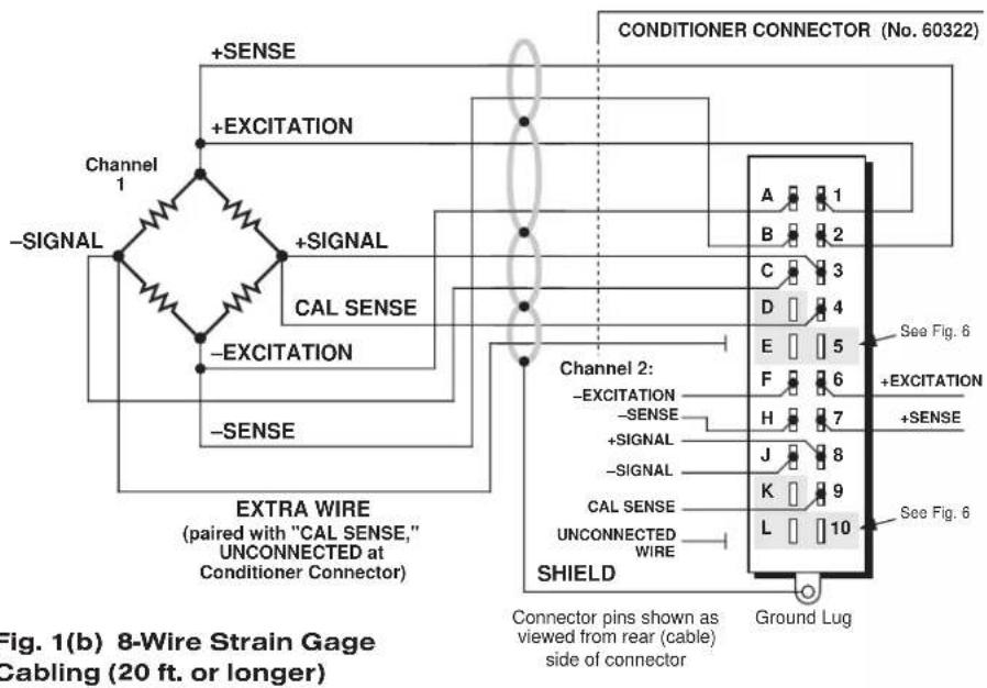
Table 2 Model 10A72-2C Pin/Terminal Assignments
I/O Connector Conditioner Conditioner Pin/Terminal Channel Line Number Number Function
1 1 + EXCITATION
A 1 - EXCITATION
21+SENSE
B 1 -SENSE
31+SIGNAL
| C | 1 | -SIGNAL |
| 4 | 1 | CAL SENSE |
| D | 1 | NOT +CALIBRATE |
| 5 | 1 | SIGNAL COMMON |
| E | 1 | NOT -CALIBRATE |
| 6 | 2 | +EXCITATION |
| F | 2 | -EXCITATION |
| 7 | 2 | +SENSE |
| H | 2 | -SENSE |
| 8 | 2 | +SIGNAL |
| J | 2 | -SIGNAL |
| 9 | 2 | CAL SENSE |
| K | 2 | NOT +CALIBRATE |
| 10 | 2 | SIGNAL COMMON |
| L | 2 | NOT -CALIBRATE |
Fig. 2 Model 10A72-2C CE-COMPLIANT Transducer Cabling


flowchart
graph TD
    A["Channel 1"] --> B["+SENSE"]
    B --> C["EXCITATION"]
    C --> D["+SIGNAL-SIGNAL"]
    D --> E["CAL SENSE"]
    E --> F["-EXCITATION"]
    F --> G["-SENSE"]
    G --> H["EXTRA WIRE (paired with "CAL SENSE," UNCONNECTED at Conditioner Connector)"]

    I["Model C12-CE CONDITIONER CONNECTOR"] --> J["1"]
    I --> K["L"]
    I --> L["10"]
    I --> M["K"]
    I --> N["K"]
    I --> O["B"]
    I --> P["J"]
    I --> Q["C"]
    I --> R["H"]
    I --> S["D"]
    I --> T["F"]
    I --> U["E"]
    I --> V["SHIELD"]
    V --> W["See Fig. 7"]

    X["Channel 2: UNCONNECTED WIRE"] --> Y["CAL SENSE"]
    Y --> Z["-SIGNAL"]
    Y --> AA["+SIGNAL"]
    Y --> AB["-SENSE"]
    Y --> AC["+SENSE"]
    Y --> AD["-EXC."]
    Y --> AE["+EXC."]
Fig. 2(b) 8-Wire Strain Gage Cabling (20 ft. or longer)

3 SETUP AND/OR OPERATING CONSIDERATIONS
3.a SELECTION OF CONDITIONER MODES
When receiving input from a conventional 4-arm strain gage bridge, a 10A72-2C channel should remain in the factory-set "TRANSDUCER" mode. When conditioning input from a 1/4-bridge (1-arm) or 1/2-bridge (2-arm) strain gage configuration, however, the channel should be set to "GAGE" mode, as follows:*
- Remove the 10A72-2C card from its mainframe slot. For "Card Insertion and Removal," see Manual Section 2.b.1.
- Refer to Fig. 4 and locate the CONDITIONER MODE PROGRAMMING JUMPER PINS for Channels 1 and 2. One "minijumper" is provided for each channel, for interconnecting adjacent jumper pins.

flowchart
graph TD
    A["Excitation Voltage Programming Jumper Pins"] --> B["Channel 1"]
    A --> C["Channel 2"]
    D["Analog Filter Programming Jumper Pins"] --> E["Channel 1"]
    D --> F["Channel 2"]
    G["Conditioner Mode Programming Jumper Pins"] --> H["TRANSDUCER"]
    G --> I["GAGE"]
    B -.-> J["10 V"]
    C -.-> K["5 V"]
    D -.-> L["1V"]
    E -.-> M["STANDARD FILTER (10-Hz)"]
    F -.-> N["100-Hz FILTER"]
    style A fill:#f9f,stroke:#333
    style D fill:#ccf,stroke:#333
    style G fill:#cfc,stroke:#333
    style B fill:#ffc,stroke:#333
    style C fill:#ffc,stroke:#333
    style E fill:#ffc,stroke:#333
    style F fill:#ffc,stroke:#333
    style G fill:#ffc,stroke:#333
    style H fill:#cfc,stroke:#333
    style I fill:#cfc,stroke:#333
* In "GAGE" mode, the 10A72-2C requires the connection of a Model 10CJB-2 Dual Bridge Completion Card, or equivalent circuitry provided by the user (see Section 4). The purpose of the "GAGE" setting is to ensure compatibility with special applications of the older Model 10A72-2 where it was not required that the "CAL SENSE" line be tied to the "+ SIGNAL" line.
- Position the jumper for each channel as shown in Fig. 4 to set the desired mode for that channel.
- Keep out the 10A72-2C card for the excitation selection procedure, below.
3.b SELECTION OF EXCITATION LEVELS
To set the DC excitation for each 10A72-2C channel, you should
- Refer to Fig. 4 and locate the EXCITATION VOLTAGE PROGRAMMING JUMPER PINS for Channels 1 and 2. One "minijumper" is provided for each channel, for interconnecting adjacent jumper pins.
- Position the jumper for each channel as shown in Fig. 4 to set the desired excitation for that channel (1, 5, or 10 V).
- Keep out the 10A72-2C card for the filter selection procedure, below.
3.c SELECTION OF ANALOG FILTERS
To set the analog filter for each 10A72-2C channel, you should
- Refer to Fig. 4 and locate the ANALOG FILTER PROGRAMMING JUMPERS PINS for Channels 1 and 2. One multi-connection "minijumper" is provided for each channel.
-
Position the jumper for each channel as shown in Fig. 4 to set the filter for that channel. For the "standard" (10-Hz) filter setting, the jumper should be placed on the left vertical row of pins, with its left edge overhanging the pin block, as shown. For the 100-Hz filter setting, the jumper should be placed directly on all six pins, in order to interconnect each of the three pairs.
-
Reinsert the 10A72-2C card in its mainframe slot.
3.d CONFIGURATION AND CALIBRATION
For initial configuration of ANALOG INPUT CHANNELS dedicated to a specific Model 10A72-2C card when used in SPS6000, see Manual Sections 3.a and 3.b.
In the SPS6000 System, you can perform any of the three following calibration methods with the Model 10A72-2C, unless it is being used with a Model 10CJB-2 Dual Bridge Completion Card (in which case a special calibration procedure is required, as explained in Section 4.c).
CALCULATED CALIBRATION
In an SPS6000 system, a nominally accurate CALCULATED CALIBRATION should be initially applied to every Model 10A72-2C channel, even if you intend to perform additional "two-point" or "shunt" calibration (see Manual Sections 3.b and 3.e.5 for a general discussion of this calibration technique). To do so, you will enter an appropriate value for each of the following parameters in the channel's Input Configuration window:
- FILTERS: This setting is fixed at a cutoff frequency of 10.00 Hz for every 10A72-2C channel, and cannot be changed.
- EXCITATION VOLTAGE: Select from the popup list the excitation level to which this channel is presently set via a programming jumper on the 10A72-2C card (Section 3.b, above). NOTE: You cannot "set" the channel's excitation voltage through the software; you are simply informing the system of the existing hardware setting.
- DESC: Enter here the desired engineering units in which the channel's final measurement value is to be expressed, as an alphanumeric string of up to four characters.
NOTE: The four following numbers will be automatically set to the highest precision that is presently displayable by the system, based on the currently entered full-scale transducer range and the system's full scale of "32767" for display A/D conversion.
Also note that the Configurator Software will display an appropriate error message if you try to enter a "Transducer" or "Output" value that is incompatible with one or more existing calibration settings. For example, it will not let you specify too much (or too little) input signal for the presently specified transducer full-scale range—or an output offset that lies outside the range allowed by previously entered calibration values.
• TRANSDUCER INFORMATION:
- FULL SCALE RANGE: Enter here the full-scale rating of the 10A72-2C channel's source transducer, expressed in the engineering units entered in the DESC field, as specified by the transducer manufacturer. NOTE: If you attempt to enter a value of full-scale range that yields either not enough or too much input signal for the card type, the software will ask you whether you want the transducer full-scale range and the full-scale output to be set equal (you may answer Ok or Cancel).
- FULL SCALE OUTPUT (ELECTRICAL UNITS): Enter here the full-scale output of the 10A72-2C channel's source transducer, expressed in mV/V, as specified by the transducer manufacturer.
• OUTPUT INFORMATION:
- FULL SCALE OUTPUT ([specified units]): Enter here the desired full-scale measurement (to be represented by a full-scale analog output of 10 V-DC), expressed in the engineering units entered in the DESC field.
- OFFSET ([specified units]): Enter here the desired zero offset to be applied to the 10A72-2C channel's measurement reading, expressed in the engineering units entered in the DESC field.
Remember that CALCULATED CALIBRATION will not go into effect until the configuration that contains the user-entered calibration values is downloaded to the SPS6000 system via the procedure given in Manual Section 3.c.4.
Two-Point (Deadweight) Calibration
If a 10A72-2C channel's initial software-calculated calibration does not yield sufficient accuracy—or if the full-scale "mV/V" rating of the strain gage transducer is unknown—additional calibration can be performed "on-line," using the Configurator Software's On-Line Calibration window or the system's front-panel display/keypad. Manual Section 3.e.6 gives general instructions for this conventional "zero and span" calibration technique.
If you want to permanently save the scaling and offset values established during deadweight calibration, be sure to apply a SAVE ONLINE CHANGES command as soon as calibration is complete (see Manual Section 3.e.4).
NOTE: Calibrated Full Scale Output (Electrical Units) and Calibrated Offset values are displayed in a 10A72-2C channel's Input Configuration window. Initially, these "calibrated" values will be the same as the last user-entered Full Scale Output and Offset values to have been downloaded to the SPS6000. However, as soon as a "zero" calibration point is entered during on-line calibration of this channel—by either the "TWO-POINT (DEADWEIGHT)" or "SIMULATED (SHUNT)" method—the "calibrated" zero offset of the output signal is automatically determined and applied by the system. As soon as a "span" calibration point is entered during on-line calibration, the "calibrated" electrical output of the source transducer is automatically determined and applied, in order to achieve the desired scaling. The displayed Calibrated Full Scale Output then represents the actual value of full-scale transducer output (in electrical units) currently in effect within the SPS6000 system, while the displayed Calibrated Offset represents the actual output offset currently in effect, in the specified engineering units. For a properly calibrated channel, there should be little difference between the actual "calibrated" output/offset values and the respective stored values—i.e., the last user-entered output/offset values to have been downloaded to the SPS6000. Ideally, the two values should be equal.
SIMULATED (SHUNT) CALIBRATION
Suitable for all 10A72-2C excitation levels, this is a convenient "shunt resistor" method, especially when overall deadweight calibration is impractical.* Here the second ("span") input is not produced by loading the source transducer, but by "simulating" a particular up-scale value of mechanical input. This known EQUIVALENT INPUT then serves to determine the SCALING FACTOR for the channel.
Like deadweight calibration, shunt calibration can be performed "on-line," using the Configurator Software's On-Line Calibration window or the system's front-panel display/keypad. You should refer to Manual Section 3.e.7 for general theory and instructions on this standard "shunt cal" technique.
If you want to permanently save the scaling and offset values established during deadweight calibration, be sure to apply a SAVE ONLINE CHANGES command as soon as calibration is complete (see Manual Section 3.e.4).
The 10A72-2C is equipped with a 100-k , 0.1% calibration resistor for each active channel. These resistors are located on turret terminals at the rear of the card (see Fig. 5). You may, if you wish, replace each channel's installed 100K shunt resistor with a resistor of another value (strain-gage transducer manufacturers often supply such resistors with their instruments).
Manual Section 3.e.7 explains how a 10A72-2C channel's shunt resistor may be easily switched in and out by means of the +SHUNT or -SHUNT button on the SPS6000
Fig. 5 Model
10A72-2C
Shunt
Calibration
Resistors

* As stated in Manual Section 3.e.7, shunt calibration is easier though generally less accurate than two-point (deadweight) calibration. It is good for an accuracy of about 0.2% (depending, of course, on the accuracy of the specified equivalent input, and on the resistor/bridge tolerance and temperature).
unit's front-panel display/keypad or in the Configurator Software's On-Line Calibration window. Note, however, that per-channel shunt calibration can be "remotely" controlled, if desired, as an alternative to using the system keypad or software. This remote calibration control is accomplished by means of logic-level inputs to the 10A72-2C card. The relevant connections are given in Fig. 6 (for "CONVENTIONAL" cabling via the standard Daytronic 60322 connector) and in Fig. 7 (for CE-COMPLIANT cabling via the Model C12-CE Conditioner Connector). NOTE THAT CE COMPLIANCE REQUIRES THE CABLE SHIELDING SHOWN IN FIG. 7.
Figs. 6(a) and 7(a) show how the "CALIBRATE POSITIVE" and "CALIBRATE NEGATIVE" commands can be independently applied to either 10A72-2C channel, without the need of an external logic reference supply.
Closing the switch in Fig. 6(a) or 7(a) to contact point "A" will produce a Logic 0 level at Pin or Terminal D ("NOT + CALIBRATE"). Since this is a negative-true logic line, the Logic 0 input will activate the "+CALIBRATE" condition of the channel. That is, it will switch in the channel's shunt resistor for a positive up-scale reading. Opening the switch to disconnect the "NOT + CALIBRATE" line from SIGNAL COMMON will then return the channel to the "NO + CALIBRATE" condition.
Similarly, closing the switch to contact point "B" will produce a Logic 0 level at Pin or Terminal E ("NOT -CALIBRATE"), thereby switching in the channel's shunt resistor for a negative up-scale reading. Opening the switch to disconnect the "NOT -CALIBRATE" line from SIGNAL COMMON will then return the channel to the "NO -CALIBRATE" condition.
You may also use active TTL logic, as illustrated in Figs. 6(b) and 7(b), to produce the “+CALIBRATE” or “-CALIBRATE” condition for either 10A72-2C channel.
Fig. 6 Logic Inputs for 10A72-2C Remote Shunt Calibration ("CONVENTIONAL" Cabling)

Fig. 7 Logic Inputs for 10A72-2C Remote Shunt Calibration (CE-COMPLIANT Cabling)

4
OPTIONAL BRIDGE COMPLETION: MODEL 10CJB-2 DUAL BRIDGE COMPLETION CARD
4.a PURPOSE
The optional Model 10CJB-2 Dual Bridge Completion Card lets you connect each of your Model 10A72-2C's inputs to a 2-wire 1/4-bridge, 3-wire 1/4-bridge, 1/2-bridge, or full-bridge strain gage configuration. Each 1/4-bridge configuration may use either 120 or 350 ohms nominal gage resistance. The function of the Model 10CJB-2 is to "complete" the connected bridge—that is, to allow it to be "seen" by the Model 10A72-2C as a full (4-arm) Wheatstone bridge.
For calibration of 10A72-2C channels originating from the Model 10CJB-2, see Section 4.c, below.
NOTE: USE OF THE MODEL 10CJB-2 DUAL BRIDGE COMPLETION CARD WITH THE MODEL 10A72-2C HAS NOT BEEN VERIFIED TO MEET CE STANDARDS, REGARDLESS OF WHETHER THE "CONVENTIONAL" OR CE-COMPLIANT I/O CONNECTOR IS BEING USED.
Fig. 8 Model 10CJB-2 Transducer Cabling


4.b 10CJB-2 TRANSDUCER CONNECTIONS
Remove the top plate of the Model 10CJB-2 box (4 screws in corners). Inside the box are two sets of labelled screw terminals, one for each of the 10A72-2C's input channels ("A" and "B"). As shown in the following figures, you will connect your gage wires directly to these terminals, and, if necessary, interconnect certain terminal pairs by means of jumper wires. Gage leads should enter the 10CJB-2 through the cutout on the right-hand side of the box.
NOTE: You must furnish your own pin-to-pin shielded cable for connecting the 10CJB-2 to the 10A72-2C's rear I/O CONNECTOR, which may be either the "conventional" Daytronic 60322 connector or the CE-compliant Model C12-CE (see the pin/terminal assignment table above)—or you may use a special cable furnished by Daytronic. In either case, Daytronic will supply terminal connectors for the cable.
Fig. 8(a) shows connections between the 10CJB-2 and a 2-wire 1/4-bridge gage configuration (represented by the single gage resistor). Here, you must install a jumper wire between the -SIG and 1/2 BR terminals, and between the +SIG terminal and either the 120 terminal or the 350 terminal, depending on the nominal gage resistance.
Fig. 8(b) shows connections between the 10CJB-2 and a 3-wire 1/4-bridge gage configuration (again represented by the single gage resistor). Here again, the -SIG and 1/2 BRterminals must be tied. The gage's third (self-compensating) lead is connected either to the 120 terminal or to the 350 terminal, depending on the nominal gage resistance.
Fig. 8(c) shows connections between the 10CJB-2 and a 1/2-bridge gage configuration (represented by the two connected gage resistors). Here again, the -SIG and 1/2 BRterminals must be tied.
Fig. 8(d) shows connections between the 10CJB-2 and a full-bridge gage configuration (represented by the four connected gage resistors).
4.c CALIBRATION
CALCULATED CALIBRATION
For 10A72-2C channels receiving strain-gage inputs from a Model 10CJB-2 Bridge Completion Card, you may use the same basic procedure as described in Section 3.d, above. Note however that, in this case,
- for FULL-SCALE OUTPUT (ELECTRICAL UNITS) under TRANSDUCER INFORMATION, you should enter one of the following full-scale "mV/V" values, whichever is appropriate for the strain-gage configuration: 0.75, 1.50, 3.00.
- for the FULL-SCALE RANGE under TRANSDUCER INFORMATION, you should enter the full-scale microstrain range that corresponds to the selected FULL-SCALE OUTPUT (ELECTRICAL UNITS) rating, as given in the following table.
Table 3 Strain Gage Microstrain Ranges (10A72-2C)
| Full-Scale Output (mV/V) | Full-Scale Microstrain Range |
| 0.75 | u = 3000 / (N · G) |
| 1.50 | u = 6000 / (N · G) |
| 3.00 | u = 12000 / (N · G) |
Here, “N” is the number of active strain-gage arms in the gage configuration. Thus, for a 1/4-bridge gage, N = 1; for a half-bridge gage, N = 2; and for a full-bridge gage, N = 4. “G” is the gage factor of the strain gage, and is normally provided by the manufacturer.
Remember that CALCULATED CALIBRATION will not go into effect until the configuration that contains the user-entered calibration values is downloaded to the SPS6000 system via the procedure given in Manual Section 3.c.4.
Two-Point (Deadweight) Calibration
See Manual Section 3.e.6 for the general procedure. Your first calibration point, entered via the Zero button, should be zero. Your second calibration point, entered via the Span button, should be expressed in microstrain (microinches/inch).
SIMULATED (SHUNT) CALIBRATION
See Manual Section 3.e.7 for the general procedure. Your EQUIVALENT INPUT value, which is entered via the +Shunt or -Shunt button (following zeroing of the channel via the Zero button), should be expressed in microstrain (microinches/inch).
Coarse Zero Offset
In the event that, during "Two-Point" or "Simulated" calibration of the 10CJB-2 channel, you are unable to set the desired span via the Span button, you can apply a positive or negative zero offset of approximately 1 mV/V for balance correction, as follows:
- Remove the top plate of the 10CJB-2 box and locate the three programming jumper pads for the channel in question. Labelled "A" for Channel 1 and "B" for Channel 2, the pads are near the left edge of the 10CJB-2 circuit board.
- Place a solder drop between the center pad and either the "+" or "-" pad, depending on the desired offset polarity.
- Re-enter your Zero and Span values (with or without calibration "shunt").
WITH OPTIONAL CONNECTOR
FOR FULL COMPLIANCE WITH

STANDARDS WHEN USED IN AN SPS6000 SYSTEM
MODEL 10A73-4
1/2 & 1/4 BRIDGE STRAIN
GAGE CONDITIONER CARD
1 GENERAL DESCRIPTION AND SPECIFICATIONS
Intended primarily for stress analysis applications, the Model 10A73-4 receives and conditions up to four independent inputs from one-arm (1/4-bridge), two-arm (1/2-bridge), and four-arm (full-bridge) strain gage configurations attached directly to the stressed material.
Unless all four inputs originate from full-bridge transducers, the 10A73-4 requires external completion of each strain gage input to full bridge, by means of one of the following:
- a Daytronic Bridge Completion Connector—one of the following models:
— 10QBC-4-120 for "CONVENTIONAL" 2- or 3-wire 120-Ω quarter-bridge connections
— 10QBC-4-350 for "CONVENTIONAL" 2- or 3-wire 350-Ω quarter-bridge connections
— 10QBC-4-1K for "CONVENTIONAL" 2- or 3-wire1000-Ω quarter-bridge connections
— 10HBC-4 for "CONVENTIONAL" 4- or 6-wire half-bridge connections
— 10FBC-4 for "CONVENTIONAL" 5-wire full-bridge connections
— CQBC120-CE for CE-COMPLIANT 2- or 3-wire 120-Ω quarter-bridge connections
— CQBC350-CE for CE-COMPLIANT 2- or 3-wire 350-Ω quarter-bridge connections
— CQBC1K-CE for CE-COMPLIANT 2- or 3-wire 1000-Ω quarter-bridge connections
— CUBC-CE for CE-COMPLIANT 4-wire (ONLY) half-bridge connections or 5-wire full-bridge connections
- a Daytronic Model 10CJB-4 Quad Bridge Completion Card (described in Section 2.b) ^1 ;
• equivalent circuitry supplied by the user ^2
This conditioner provides selectable low-level excitation (1, 2, or 5 V-DC) to help reduce gage heating effects in materials with low thermal conductivity. ^3 However, the selection of excitation level for the 10A73-4 is not “per channel”; the same level applies to all four 10A73-4 channels.
^1 The 10CJB-4 contains a switch for easy selection of the common excitation level.
NOTE: USE OF THE MODEL 10CJB-4 QUAD BRIDGE COMPLETION CARD WITH THE MODEL 10A73-4 HAS NOT BEEN VERIFIED TO MEET CE STANDARDS.
2 If you wish to provide your own bridge-completion circuitry, you should contact the factory for instructions on connections and calibration.
3 Except when a "CONVENTIONAL" Bridge Completion Connector is used with the Model 10A73-4. In this case, the excitation is fixed at 5 V, unless a special modification is made to the card.
The 10A73-4 can be quickly calibrated through a convenient shunt technique, following initial “calculated calibration” via the Configurator Software. Unless a “CONVENTIONAL” Bridge Completion Connector is being used with the 10A73-4, all four shunt resistors may be switched in and out simultaneously by means of logic-level inputs through the rear I/O CONNECTOR.
ADDITIONAL 10A73-4 SPECIFICATIONS
Transducer Types: 1/4-, 1/2-, or full-bridge strain-gage configurations. 2-wire or 3-wire 1/4-bridge configurations may use either 120 Ω, 350 Ω, or 1 kΩ nominal gage resistance; full-bridge configurations should use 350-Ω gages (or higher) or should use 120-Ω gages with either 1-V or 2-V excitation. Unless all four inputs originate from full-bridge transducers, the Model 10A73-4 requires either an appropriate "CONVENTIONAL" or CE-COMPLIANT Daytronic Bridge Completion Connector; a Model 10CJB-4 Quad Bridge Completion Card*; or equivalent bridge-completion circuitry supplied by the user.
Transducer Ranges: ±0.750, 1.500, or 3.000 mV/V; for "type" codes assigned to 10A73-4 data channels, see Appendix A of the latest Daytronic Conditioner Cards Catalog
Excitation (for all four channels): Sensed excitation selectable 1, 2, or 5 V-DC (i.e., ±0.5, ±1, or ±2.5 V-DC, respectively), nominal
Amplifier (per channel):
Common-Mode Range: ±0.4 V operating; ±5 V without instrument damage
Common-Mode Rejection Ratio: DC: -90 dB; at 60 Hz, 1 kHz, and 3 kHz: -120 dB
Input Impedance: Differential: greater than 100 MΩ; Common-Mode: greater than 100 MΩ
Offset: Initial: ±0.04% of full scale; vs. temperature: ±20 ppm/°C; vs. time: ±10 ppm/month
Gain Accuracy**: ±0.02% of full scale with 5-V excitation; ±0.02% of full scale with 1-V or 2-V excitation typical, following calibration
Gain Stability: vs. temperature: ±50 ppm/°C; vs. time: ±20 ppm/month
Filter: 3-pole modified Butterworth; 3 dB down at 10 Hz; 60 dB down at 100 Hz
Step-Response Settling Time (Full-Scale Output):
To 1% of final value: 100 msec
To 0.1% of final value: 150 msec
To 0.02% of final value: 600 msec
Auxiliary Output: Filtered outputs available as input to an Analog Signal Processor Card
* See first note on the previous page.
** Initial (uncalibrated) inaccuracy with 1-V or 2-V excitation may be as great as ±0.1% of full scale. Maximum error that could occur upon replacement of a Model 10A73-4 not followed by calibration is ±0.2% of full scale.
2 GAGE / TRANSDUCER CONNECTIONS
IMPORTANT
The type of Daytronic Bridge Completion Connector to be used with the Model 10A73-4 will depend on whether or not you wish your SPS6000 system to comply with CE standards.
If CE compliance is NOT required, you may use any of the five "CONVENTIONAL" completion connectors (Model 10QBC-4-120, 10QBC-4-350, 10QBC-4-1K, 10HBC-4 or 10FBC-4), which must be ordered separately from the 10A73-4 card. You may alternatively use a separately ordered Model 10CJB-4 Quad Bridge Completion Card.
If CE compliance is required, you MUST use one of the four CE-COMPLIANT completion connectors (Model CQBC120-CE, CQBC350-CE, CQBC1K-CE, or CUBC-CE), which must be ordered separately from the 10A73-4 card. NOTE THAT USE OF THE MODEL 10CJB-4 QUAD BRIDGE COMPLETION CARD WITH THE MODEL 10A73-4 HAS NOT BEEN VERIFIED TO MEET CE STANDARDS.
ALSO NOTE: CE COMPLIANCE FURTHER REQUIRES THE CABLE SHIELDING SHOWN IN FIG. 3(a), 3(b), 3(c), or 3(d). For more information on the “CONNECTION OF CABLE SHIELD,” see Manual Section 2.b.3.
Table 1, below, gives pin assignments for the 10A73-4's rear I/O CONNECTOR, to which appropriate BRIDGE COMPLETION CIRCUITRY must be attached, unless all four inputs originate from full-bridge transducers.
Section 2.a describes the cabling to be used with both “CONVENTIONAL” and CE-COMPLIANT Daytronic Bridge Completion Connectors.
Section 2.b describes the cabling to be used with the Model 10CJB-4 Quad Bridge Completion Card (NOT CE-COMPLIANT).
Section 2.c describes the cabling to be used in the absence of bridge-completion circuitry (i.e., connection to four full-bridge transducers). THIS CABLING HAS NOT BEEN VERIFIED TO MEET CE STANDARDS.
IMPORTANT: The ±EXCITATION, ±SENSE, and ±SIGNAL pins or terminals for an UNUSED STRAIN GAGE INPUT CHANNEL should be jumpered at the I/O CONNECTOR or in the BRIDGE COMPLETION CONNECTOR as shown in Fig. 1, below (which applies to either “conventional” or CE-compliant cabling). If an input is left open, high-

flowchart
graph TD
    A["Model 10A73-4 I/O Connector or Bridge Completion Card"] --> B["+EX (All Chns.)"]
    A --> C["+SEN (All Chns.)"]
    A --> D["-EX (All Chns.)"]
    A --> E["-SEN (All Chns.)"]
    A --> F["+SIG (Chn. n)"]
    A --> G["-SIG (Chn. n)"]
    A --> H["PWR COM or SHIELD (All Chns.)"]
    B --> I["THESE JUMPERS ARE NEEDED IF AND ONLY IF THE ENTIRE 10A73-4 CARD IS INSTALLED BUT UNUSED."]
    C --> I
    D --> I
    E --> I
    F --> I
    G --> I
    H --> I
    style A fill:#f9f,stroke:#333
    style B fill:#ccf,stroke:#333
    style C fill:#ccf,stroke:#333
    style D fill:#ccf,stroke:#333
    style E fill:#ccf,stroke:#333
    style F fill:#ccf,stroke:#333
    style G fill:#ccf,stroke:#333
frequency oscillation can result, which can in turn produce significant interchannel crosstalk, and possibly inaccurate data readings.
ALSO NOTE: Logic connections for remote control of shunt calibration (using the I/O CONNECTOR'S or BRIDGE COMPLETION CONNECTOR'S "NOT ±CALIBRATE" pins or terminals) are discussed in Section 3.b and shown in Figs. 10 and 11. Note that these logic-level inputs are not available for use when a "CONVENTIONAL" Bridge Completion Card is attached to the 10A73-4.
Table 1 Model 10A73-4 Pin Assignments
| I/O Connector Conditioner ConditionerPin Channel LineNumber Number Function | ||
| 1 1 +SIGNAL | ||
| A 1 -SIGNAL | ||
| 2 1 CAL SENSE | ||
| B * +EXCITATION | ||
| 3 2 +SIGNAL | ||
| C 2 -SIGNAL | ||
| 4 2 CAL SENSE | ||
| D * +SENSE | ||
| 5 3 +SIGNAL | ||
| E 3 -SIGNAL | ||
| 6 3 CAL SENSE | ||
| F | * | -SENSE |
| 7 4 +SIGNAL | ||
| H 4 -SIGNAL | ||
| 8 4 CAL SENSE | ||
| J | * | -EXCITATION |
| 9 | * | NOT +CALIBRATE |
| K * | EXC PROGRAMMING | |
| 10 | * | NOT -CALIBRATE |
| L | * | POWER COMMON |
2.a 1/4-, 1/2-, OR FULL-BRIDGE GAGE CONNECTIONS USING A DAYTRONIC BRIDGE COMPLETION CONNECTOR
Each Bridge Completion Connector attaches directly to the rear I/O CONNECTOR of the Model 10A73-4.
Remove the top plate of the connector. Inside are four sets of labelled screw terminals, corresponding to the 10A73-4's four input channels. You will connect your gage wires directly to these terminals and, if necessary, interconnect certain terminal pairs by means of jumper wires. All gage leads should be securely clamped by means of the two cable clamps.
Fig. 2 shows per-channel connections between external strain-gage configurations and the respective "CONVENTIONAL" Bridge Completion Connectors. Fig. 3 shows per-channel connections for the respective CE-COMPLIANT Bridge Completion Connectors. Note that the CE-compliant Model CUBC-CE cannot accommodate the 6-wire 1/2-bridge cabling shown for the Model 10HBC-4 in Fig. 2(d).
NOTE ALSO: Unlike the Model 10CJB-4, the Bridge Completion Connectors (both "conventional" and CE-compliant) DO NOT PERMIT MIXING OF CONNECTED GAGE CONFIGURATION TYPES. That is, all gage configurations connected to the same Bridge Completion Connector must be of the same appropriate type (e.g., 120-Ω 1/4-bridge, 1/2-bridge, etc.).
When input connections involve pairs of EXCITATION, SENSE, and/or SIGNAL lines, these should be twisted pairs within the input cable. While it is desirable to shield such pairs individually (as shown in the figures), this is not necessary for "CONVENTIONAL" BRIDGE COMPLETION; an overall cable shield is acceptable. For CE-COMPLIANT BRIDGE COMPLETION, the shielding shown in Fig. 3 MUST be adopted.
Note too that the full-bridge input connections given in Figs. 2(e) and 3(d) are to be used if one or more of the 10A73-4's other inputs derives from a less than full-bridge configuration. If all four inputs originate from full-bridge configurations, no completion circuitry is required (see Section 2.c and Fig. 5).
Fig. 2 Model 10A73-4 Strain Gage Cabling Using "CONVENTIONAL" Daytronic Bridge Completion Connectors


flowchart
graph LR
    A["Signal"] -->|+Excitation| B["+EXC"]
    A -->|-Excitation| C["-EXC"]
    B --> D["+SENSE"]
    C --> E["SHIELD"]
    D --> F["CAL SEN"]
    E --> G["-SENSE"]
    F --> H["+SIGNAL"]
    G --> I["-SIGNAL"]
    H --> J["Twisted Pair"]
    I --> J
    J --> K["Model 10HBC-4"]
Fig. 2(c) Per-Channel Connections to Model 10HBC-4 for 4-Wire 1/2-Bridge Completion
* I.e., Model QBC-4-120, QBC-4-350, or QBC-4-1K.
Fig. 2(d) Per-Channel Connections to Model 10HBC-4 for 6-Wire 1/2-Bridge Completion

flowchart
graph TD
    A["+Excitation"] --> B["Swisted Pair"]
    C["Signal"] --> B
    D["-Excitation"] --> B
    B --> E["Model 10HBC-4"]
    E --> F["+EXC"]
    E --> G["+SENSE"]
    E --> H["CAL SEN"]
    E --> I["+SIGNAL"]
    E --> J["-SENSE"]
    E --> K["-EXC"]
    E --> L["SHIELD"]
Fig. 2(e) Per-Channel Connections to Model 10FBC-4 for Full-Bridge Connection

flowchart
graph TD
    A["Resistors"] --> B["+Excitation"]
    B --> C["Swisted Pair"]
    C --> D["+EXC"]
    C --> E["CAL SEN"]
    C --> F["+SIGNAL"]
    C --> G["-SIGNAL"]
    C --> H["-EXC"]
    C --> I["SHIELD"]
    J["Signal"] --> K["+Excitation"]
    K --> L["Swisted Pair"]
    L --> M["+EXC"]
    L --> N["CAL SEN"]
    L --> O["+SIGNAL"]
    L --> P["-SIGNAL"]
    L --> Q["-EXC"]
    L --> R["SHIELD"]
Fig. 3 Model 10A73-4 Strain Gage Cabling Using CE-COMPLIANT Daytronic Bridge Completion Connectors

* I.e., Model CQBC120-CE, CQBC350-CE, or CQBC1K-CE.
Fig. 3(b) Per-Channel Connections to Model CQBC-CE* for 3-Wire 1/4-Bridge Completion
Model CQBC120-CE
Model CQBC350-CE
OR
Model CQBC1K-CE
CONDITIONER CONNECTOR

Fig. 3(c) Per-Channel Connections to Model CUBC-CE for 4-Wire 1/2-Bridge Completion

flowchart
graph TD
    A["+Excitation"] --> B["Twisted Pair"]
    B --> C["Signal"]
    C --> D["-Excitation"]
    D --> E["Model CUBC-CE CONDITIONER CONNECTOR"]
    E --> F["+EXC"]
    E --> G["RES (RESISTOR)"]
    E --> H["CAL"]
    E --> I["+SIG"]
    E --> J["-SIG"]
    E --> K["H.B. (HALF BRIDGE)"]
    E --> L["-EXC"]
    E --> M["SHIELD"]
Fig. 3(d) Per-Channel Connections to Model CUBC-CE for Full-Bridge Connection

flowchart
graph TD
    A["Excitation"] --> B["+Excitation"]
    B --> C["+Signal"]
    C --> D["Swisted Pair"]
    D --> E["SWIELD"]
    F["Excitation"] --> G["-Excitation"]
    G --> H["Signal"]
    H --> I["Twisted Pair"]
    I --> J["SWIELD"]
    K["SWIELD"] --> L["H.B. (HALF BRIDGE)"]
    L --> M["-EXC"]
    L --> N["SHIELD"]
    O["+EXC"] --> P["RES (RESISTOR)"]
    Q["CAL"] --> R["+SIG"]
    S["-SIG"] --> T["-SIG"]
    U["+SIG"] --> V["+SIG"]
    W["+EXC"] --> X["RES (RESISTOR)"]
* I.e., Model CQBC120-CE, CQBC350-CE, or CQBC1K-CE.
2.b 1/4-, 1/2-, OR FULL-BRIDGE GAGE CONNECTIONS USING THE MODEL 10CJB-4
Remove the top plate of the Model 10CJB-4 box (4 screws in corners). Inside the box are four sets of labelled screw terminals, one for each of the 10A73-4's input channels ("A," "B," "C," and "D"). As shown in the following figures, you will connect your gage wires directly to these terminals, and, if necessary, interconnect certain terminal pairs by means of jumper wires. Gage leads should enter the 10CJB-4 through the cutout on the right-hand side of the box.
NOTE: You must furnish your own pin-to-pin shielded cable for connecting the 10CJB-4 to the 10A73-4's rear I/O CONNECTOR (see Table 1 for pin assignments)—or you may use a special cable furnished by Daytronic. In either case, Daytronic will supply terminal connectors for the cable.
Fig. 4(a) shows connections between the 10CJB-4 and a 2-wire 1/4-bridge gage configuration (represented by the single gage resistor). Here, you must install a jumper wire between the -SIG and 1/2 BR terminals, and between the +SIG terminal and either the 120 terminal or the 350 terminal, depending on the nominal gage resistance.
Fig. 4 Model 10CJB-4 Transducer Cabling

flowchart
graph TD
    A["Signal"] --> B["Excitation"]
    B --> C["-SIG"]
    B --> D["1/2 BR"]
    B --> E["-EX"]
    B --> F["120"]
    B --> G["350"]
    B --> H["+SIG"]
    B --> I["+EX"]
    J["Model 10CJB-4 Screw Terminal (Chn. 1, 2, 3, or 4)"]

flowchart
graph TD
    A["Signal"] --> B["Excitation"]
    B --> C["-SIG"]
    B --> D["1/2 BR"]
    B --> E["-EX"]
    C --> F["120"]
    D --> G["350"]
    E --> H["+SIG"]
    F --> I["+EX"]
    G --> J["+SIG"]
    H --> K["+EX"]

flowchart
graph TD
    A["Model 10CJB-4 Screw Terminal (Chn. 1, 2, 3, or 4)"] --> B["−SIG"]
    A --> C["1/2 BR"]
    A --> D["−EX"]
    A --> E["120"]
    A --> F["350"]
    A --> G["+SIG"]
    A --> H["+EX"]
    I["Signal"] --> J["−Excitation"]
    K["+Excitation"] --> L["−Excitation"]

Fig. 4(b) shows connections between the 10CJB-4 and a 3-wire 1/4-bridge gage configuration (again represented by the single gage resistor). Here again, the -SIG and 1/2 BR terminals must be tied. The gage's third (self-compensating) lead is connected either to the 120 terminal or to the 350 terminal, depending on the nominal gage resistance.
Fig. 4(c) shows connections between the 10CJB-4 and a 1/2-bridge gage configuration (represented by the two connected gage resistors). Here again, the -SIG and 1/2 BR terminals must be tied.
Fig. 4(d) shows connections between the 10CJB-4 and a full-bridge gage configuration (represented by the four connected gage resistors).
2.c FULL-BRIDGE TRANSDUCER CONNECTIONS (WITHOUT BRIDGE COMPLETION)
In the absence of bridge-completion circuitry, the 10A73-4's I/O CONNECTOR will mate with Daytronic CONDITIONER CONNECTOR No. 60322. This is the "CONVENTIONAL" 20-pin connector for a "10A" card, as described in Manual Section 2.b.3; there is no equivalent CE-compliant connector for the 10A73-4. Pinout for the I/O CONNECTOR is given in Table 1, above. The required cabling is shown in Fig. 5. THIS CABLING HAS NOT BEEN VERIFIED TO MEET CE STANDARDS.
Note that the main 16-wire shielded cable should contain 20- to 24-gage wires. The length of the main cable—i.e., the distance from the 10A73-4's rear I/O CONNECTOR to the two “sensing points”—may be up to 500 feet. At the sensing points, the + SENSE and -SENSE lines join the corresponding EXCITATION lines, and the main cable divides into four separately shielded 5-wire cables (one to each full-bridge transducer). These secondary cables should contain 16- to 20-gage wires. It is important that the distance “D” from the sensing points to each transducer be as short as possible; a maximum error of 0.02% could arise for every 3.5 ft. of 20-gage wire over the distance “D,” and for every 9 ft. of 16-gage wire.

flowchart
graph TD
    A["Channel 1"] --> B["+Signal (CHN. 1)"]
    A --> C["CAL. SENSE (CHN. 1)"]
    A --> D["-Signal (CHN. 1)"]
    E["Channel 2"] --> F["+Signal (CHN. 2)"]
    E --> G["CAL. SENSE (CHN. 2)"]
    E --> H["-Signal (CHN. 2)"]
    I["Channel 3"] --> J["+Signal (CHN. 3)"]
    I --> K["CAL. SENSE (CHN. 3)"]
    I --> L["-Excitation"]
    M["Channel 4"] --> N["+Signal (CHN. 4)"]
    M --> O["CAL. SENSE (CHN. 4)"]
    M --> P["-Signal (CHN. 4)"]
    Q["Sensing Points"] --> R["+Excitation +Sense"]
    Q --> S["-Excitation"]
    T["SHIELD"] --> U["Connector pins shown as viewed from rear (cable) side of connector."]
    V["Conditioner Connector (No. 60322)"] --> W["A"]
    V --> X["B"]
    V --> Y["C"]
    V --> Z["D"]
    V --> AA["E"]
    V --> AB["F"]
    V --> AC["H"]
    V --> AD["J"]
    V --> AE["K"]
    V --> AF["L"]
    V --> AG["10"]
    AH["See Fig. 10"] --> AI["Ground Lug"]
    AJ["SHIELD"] --> AK["Ground Lug"]
Fig. 5 10A73-4 Cabling to Four Full-Bridge Transducers
3
SETUP AND/OR OPERATING CONSIDERATIONS
When a CE-COMPLIANT Bridge Completion Connector (Model CQBC120-CE, CQBC350-CE, CQBC1K-CE, or CUBC-CE) is used with the Model 10A73-4, you will use the connector's "TRACK" terminal to set the excitation level for all four 10A73-4 channels to 1, 2, or 5 volts, as indicated in Fig. 6. Note that 5 volts is selected when the "TRACK" terminal is left unconnected.
Fig. 6 Model
10A73-4 Excitation
Selection Via the
TRACK Terminal of
a CE-COMPLIANT
Bridge Completion
Connector

To select 1-V excitation, connect TRACK Terminal to -EXCITATION Terminal

To select 2-V excitation, connect TRACK Terminal to COMMON Terminal

To select 5-V excitation, leave TRACK Terminal unconnected
When a "CONVENTIONAL" Bridge Completion Connector (Model 10QBC-4-120, 10QBC-4-350, 10QBC-4-1K, 10HBC-4, or 10FBC-4) is used with the Model 10A73-4, the excitation level for all four channels is fixed at 5 volts, and cannot be changed without a special modification to the 10A73-4 card.
When the Model 10CJB-4 Quad Bridge Completion Card is used with the Model 10A73-4, you will use the three-position switch on the 10CJB-4 board to set the excitation level for all four 10A73-4 channels to 1, 2, or 5 volts. The switch is shown in Fig. 7, below.
When a Bridge Completion Card or 10CJB-4 is absent, you may use Pin K of the 10A73-4's rear I/O CONNECTOR to select the desired excitation for all four channels, as indicated in Fig. 8. Leaving Pin K open selects an excitation of 5 volts; tying Pin K to Pin L selects 2 volts; and tying Pin K to Pin J selects 1 volt.
Fig. 7 Model 10CJB-4 Offset Jumpers and Excitation Selection Switch


3.b CONFIGURATION AND CALIBRATION
For initial configuration of ANALOG INPUT CHANNELS dedicated to a specific Model 10A73-4 card when used in SPS6000, see Manual Sections 3.a and 3.b.
When a Model 10A73-4 in an SPS6000 system is connected to quarter-bridge or half-bridge gage configurations for purposes of stress analysis, you can perform both "CALCULATED" and "SIMULATED (SHUNT)" calibration of any of its input channels, regardless of the type of bridge completion being used for that channel. In general, the conventional "TWO-POINT (DEADWEIGHT)" method does not apply in such cases.
When a 10A73-4 is connected to full-bridge strain gage transducers, "TWO-POINT (DEADWEIGHT)" calibration may be applied, in addition to or as an alternative to "CAL-CULATED" and "SIMULATED (SHUNT)" calibration.
NOTE: If you are using a Model 10CJB-4 for bridge completion of a 10A73-4 channel and, prior to initial calibration, observe a significantly nonzero reading when no load is placed on the gage(s), you may impose a nominal ±1 mV/V offset by means of solder pads in the 10CJB-4 box. See Section 3.c for complete instructions.
CALCULATED CALIBRATION
In an SPS6000 system, a nominally accurate CALCULATED CALIBRATION should be initially applied to every Model 10A73-4 channel, even if you intend to perform additional "two-point" or "shunt" calibration (see Manual Sections 3.b and 3.e.5 for a general discussion of this calibration technique). To do so, you will enter an appropriate value for each of the following parameters in the channel's Input Configuration window:
- FILTERS: This setting is fixed at a cutoff frequency of 10.00 Hz for every 10A73-4 channel, and cannot be changed.
• TRANSDUCER: The only presently available selection is STRAIN GAGE. - DESC: Enter here the desired engineering units in which the channel's final measurement value is to be expressed, as an alphanumeric string of up to four characters.
NOTE: The four following numbers will be automatically set to the highest precision that is presently displayable by the system, based on the currently entered full-scale transducer range and the system's full scale of "32767" for display A/D conversion.
Also note that the Configurator Software will display an appropriate error message if you try to enter a "Transducer" or "Output" value that is incompatible with one or more existing calibration settings. For example, it will not let you specify too much (or too little) input signal for the presently specified transducer full-scale range—or an output offset that lies outside the range allowed by previously entered calibration values.
• TRANSDUCER INFORMATION:
- FULL SCALE RANGE: Enter here the nominal full-scale rating of the channel's gage(s) in microstrain (microinches/inch), as specified by the gage manufacturer. The following table gives full-scale microstrain range values corresponding to standard values of FULL-SCALE OUTPUT (ELECTRICAL UNITS). NOTE: If you attempt to enter a value of full-scale range that yields either not enough or too much input signal for the card type, the software will ask you whether you want the transducer full-scale range and the full-scale output to be set equal (you may answer Ok or Cancel).
Table 2 Strain Gage Microstrain Ranges (10A73-4)
| Full-ScaleOutput (mV/V Microstrain Range | Full-Scale |
| 0.750 3000 / (N · G) | |
| 1.500 6000 / (N · G) | |
| 3.000 12000 / (N · G) |
Here, “N” is the number of active strain-gage arms in the gage configuration. Thus, for a 1/4-bridge gage, N = 1; for a half-bridge gage, N = 2; and for a full-bridge gage, N = 4. “G” is the gage factor of the strain gage, and is normally provided by the manufacturer.
- FULL SCALE OUTPUT (ELECTRICAL UNITS): Enter here the sensitivity rating of the channel's gage(s) in "mV/V," as specified by the gage manufacturer.
• OUTPUT INFORMATION:
- FULL SCALE OUTPUT ([specified units]): Enter here the desired full-scale measurement (to be represented by a full-scale analog output of 10 V-DC), expressed in the engineering units entered in the DESC field.
- OFFSET ([specified units]): Enter here the desired zero offset to be applied to the 10A73-4 channel's measurement reading, expressed in the engineering units entered in the DESC field.
Remember that CALCULATED CALIBRATION will not go into effect until the configuration that contains the user-entered calibration values is downloaded to the SPS6000 system via the procedure given in Manual Section 3.c.4.
TWO-POINT (DEADWEIGHT) CALIBRATION
PLEASE NOTE: AS MENTIONED ABOVE, THIS CALIBRATION TECHNIQUE GENERALLY APPLIES TO A MODEL 10A73-4 CHANNEL ONLY WHEN THAT CHANNEL IS CONNECTED TO A FULL-BRIDGE STRAIN GAGE TRANSDUCER, AS ARE THE FOUR CHANNELS SHOWN IN FIG. 5.
If a 10A73-4 channel's initial software-calculated calibration does not yield sufficient accuracy—or if the full-scale "mV/V" rating of the strain gage transducer is unknown—additional calibration can be performed "on-line," using the Configurator Software's On-Line Calibration window or the system's front-panel display/keypad. Manual Section 3.e.6 gives general instructions for this conventional "zero and span" calibration technique.
If you want to permanently save the scaling and offset values established during deadweight calibration, be sure to apply a SAVE ONLINE CHANGES command as soon as calibration is complete (see Manual Section 3.e.4).
NOTE: Calibrated Full Scale Output (Electrical Units) and Calibrated Offset values are displayed in a 10A73-4 channel's Input Configuration window. Initially, these "calibrated" values will be the same as the last user-entered Full Scale Output and Offset values to have been downloaded to the SPS6000. However, as soon as a "zero" calibration point is entered during on-line calibration of this channel—by either the "TWO-POINT (DEADWEIGHT)" or "SIMULATED (SHUNT)" method—the "calibrated" zero offset of the output signal is automatically determined and applied by the system. As soon as a "span" calibration point is entered during on-line calibration, the "calibrated" electrical output of the source transducer is automatically determined and applied, in order to achieve the desired scaling. The displayed Calibrated Full Scale Output then represents the actual value of full-scale transducer output (in electrical units) currently in effect within the SPS6000 system, while the displayed Calibrated Offset represents the actual output offset currently in effect, in the specified engineering units. For a properly calibrated channel, there should be little difference between the actual "calibrated" output/offset values and the respective stored values—i.e., the last user-entered output/offset values to have been downloaded to the SPS6000. Ideally, the two values should be equal.
SIMULATED (SHUNT) CALIBRATION
This is a convenient “shunt resistor” method, especially when overall deadweight calibration is impractical.* Here the second (“span”) input is not produced by loading the source transducer, but by “simulating” a particular up-scale value of mechanical input. This known EQUIVALENT INPUT then serves to determine the SCALING FACTOR for the channel. For a 10A73-4 channel with bridge completion—by means either of a Daytronic Bridge Completion Connector or the Model 10CJB-4—the EQUIVALENT INPUT should be expressed in microstrain (microinches/inch).

Like deadweight calibration, shunt calibration can be performed "on-line," using the Configurator Software's On-Line Calibration window or the system's front-panel display/keypad. You should refer to Manual Section 3.e.7 for general theory and instructions on this standard "shunt cal" technique.
If you want to permanently save the scaling and offset values established during deadweight calibration, be sure to apply a SAVE ONLINE CHANGES command as soon as calibration is complete (see Manual Section 3.e.4).
The 10A73-4 is equipped with a 100-kΩ, 0.1% calibration resistor for each active channel. These resistors are located on turret terminals at the rear of the card (see Fig. 9). You may, if you wish, replace each channel's installed 100K shunt resistor with a resistor of another value (strain-gage transducer manufacturers often supply such resistors with their instruments).
Manual Section 3.e.7 explains how an individual 10A73-4 channel's shunt resistor may be easily switched in and out by means of the +SHUNT or -SHUNT button on the SPS6000 unit's front-panel display/keypad or in the Configurator Software's On-Line Calibration window. Note, however, that all four channels' calibration shunts can be simultaneously and "remotely" controlled, if desired, as an alternative to using the system keypad or software, provided that a "CONVENTIONAL" BRIDGE COMPLETION CONNECTOR is not attached to the conditioner. When the 10A73-4 is using any version of the Model 10QBC-4, 10HBC-4 or 10FBC-4, shunt control can only be effected via the keypad or software.
Remote calibration control is accomplished by means of logic-level inputs to the 10A73-4 card. The relevant connections are given in Fig. 10 for "CONVENTIONAL" cabling to full-bridge strain gage transducers via the standard Daytronic 60322 connector, as in Fig. 5. Calibration control connections are given in Fig. 11 for CE-COM-PLIANT bridge completion cabling via a Model CQBC120-CE, CQBC350-CE, CQBC1K-CE, or CUBC-CE. NOTE THAT CE COMPLIANCE REQUIRES THE CABLE SHIELDING SHOWN IN FIG. 11.
Figs. 10(a) and 11(a) show how the "CALIBRATE POSITIVE" and "CALIBRATE NEGATIVE" commands can be independently applied to all four 10A73-4 channels simultaneously, without the need of an external logic reference supply.
Closing the switch in Fig. 10(a) or 11(a) to contact point "A" will produce a Logic 0 level on the "NOT +CALIBRATE" line (Pin 9 of the 60322; the +SHUNT Terminal of the Bridge Completion Connector). Since this is a negative-true logic line, the Logic 0 input will activate the "+CALIBRATE" condition for all four channels. That is, it will switch in each channel's shunt resistor for a positive up-scale reading. Opening the switch to disconnect the "NOT +CALIBRATE" line from POWER COMMON will then return all channels to the "NO +CALIBRATE" condition.
Similarly, closing the switch to contact point "B" will produce a Logic 0 level on the "NOT -CALIBRATE" line (Pin 10 of the 60322; the -SHUNT Terminal of the Bridge Completion Connector), thereby switching in each channel's shunt resistor for a nega-
tive up-scale reading. Opening the switch to disconnect the "NOT-CALIBRATE" line from POWER COMMON will then return all channels to the "NO-CALIBRATE" condition.
You may also use active TTL logic, as illustrated in Figs. 10(b) and 11(b), to produce the "+CALIBRATE" or "-CALIBRATE" condition for all four 10A73-4 channels.
Fig. 10 Logic Inputs for 10A73-4 Remote Shunt Calibration (Without Bridge Completion)

Fig. 11 Logic Inputs for 10A73-4 Remote Shunt Calibration (Via CE-COMPLIANT Bridge Completion Connector)
Fig. 11(a) Switch Closure, No External Supply

Fig. 11(b) Active TTL Logic

3.c SETTING AN INITIAL ZERO OFFSET WITH THE MODEL 10CJB-4
Often the very process of mounting strain gages to the stressed material can introduce a significant residual strain, which will become apparent as a large nonzero offset in the data reading prior to initial calibration. When you are using the Model 10CJB-4 Quad Bridge Completion Card with the Model 10A73-4, you can remove at least a portion of this initial strain component for a given 10A73-4 channel by applying an approximate 1 mV/V positive or negative offset, as follows:
- Remove the top plate of the 10CJB-4 box (4 screws in corners).
- Refer to Fig. 7 and locate the set of three "1 MV/V OFFSET" jumper pads corresponding to the channel in question (like the 10CJB-4's terminal blocks, the pad sets are labelled "A," "B," "C," and "D"—corresponding to 10A73-4 Subchannel Nos 1, 2, 3, and 4, respectively).
- Remove all load from the source gage(s).
- Observe the data reading of the channel. If it is a positive nonzero value, apply a negative 1 mV/V offset by carefully placing a solder drop between the center pad and the “−” pad. If it is a negative nonzero value, place a solder drop between the center pad and the “+” pad.
- Now calibrate the channel to remove any remaining offset.
WITH OPTIONAL CONNECTOR
FOR FULL COMPLIANCE WITH

STANDARDS WHEN USED IN AN SPS6000 SYSTEM
MODEL 10A78
AC STRAIN GAGE
CONDITIONER CARD
1 GENERAL DESCRIPTION AND SPECIFICATIONS
The Model 10A78 is a single-channel conditioner of phase-sensitive carrier-amplifier design (rather than a two-channel, fully DC instrument). Intended for applications involving transformer-coupling to the transducer bridge (as with rotary-transformer torque sensors), this conditioner can also be used in conventional installations when high sensitivity is required or where the electrical environment is especially noisy. Responding only to the modulated carrier frequency, the 10A78 rejects extraneous voltages that can cause errors in DC systems, particularly when there is a need to "blow up" a portion of the transducer range. User-adjustable phase and symmetry controls are provided.
The Model 10A78's data channel is best calibrated by means of a “two-point (dead-weight)” or shunt-calibration technique, following an initial “calculated” calibration. The supplied calibration resistor is 59 kilohms, 1%. Note that a specially modified version of the 10A78 is required if you wish to control the shunt-calibration process by means of logic-level inputs through the rear I/O CONNECTOR.
ADDITIONAL 10A78 SPECIFICATIONS
Transducer Types: Conventional 4-arm strain gage bridges, nominal 350 ohms (or higher)
Input Ranges (Full-Scale): ±0.75, 1.50, or 3.00 mV/V; automatically selected—on an individual channel basis—when the channel is configured; for “type” codes assigned to 10A78 data channels, see Appendix A of the latest Daytronic Conditioner Cards Catalog. Since channel zeroing is by digital techniques, no input balance control is provided. The allowable input range, therefore, must include any initial unbalance (which, in commercially produced strain gage transducers, is usually negligible). Other transducers may have to be externally trimmed to be used with the Model 10A78, if zero unbalance exceeds 20% of full scale.
Excitation: Regulated 3 V-AC (rms) at 3280 Hz; 50 mA (rms), maximum
Amplifier:
Common-Mode Range: ±1 V operating; ±9 V without instrument damage
Common-Mode Rejection Ratio: DC and at 60 Hz: infinite; at 3 kHz: -60 dB
Input Impedance (Differential and Common-Mode): 10 MΩ
Offset: Initial: ±3% of full scale; vs. Temperature: ±0.005% f.s./°C; vs. Time: ±0.02% f.s./month
Gain Accuracy*: ±0.02% of full scale typical, following calibration
(cont'd)
* Initial (uncalibrated) inaccuracy may be as great as ±3% of full scale. Maximum error that could occur upon replacement of a Model 10A78 not followed by calibration is ±6% of full scale.
Gain Stability: vs. Temperature: ±50 ppm/°C; vs. Time: ±20 ppm/month
Filter: 3-pole modified Butterworth; 3 dB down at 7.5 Hz; 60 dB down at 60 Hz
Step-Response Settling Time (Full-Scale Output):
To 1% of final value: 250 msec
To 0.1% of final value: 350 msec
To 0.02% of final value: 500 msec
Auxiliary Output: Filtered output available as input to an Analog Signal Processor Card
2 TRANSDUCER CONNECTIONS
IMPORTANT
The type of I/O CONNECTOR to be used with the Model 10A78 will depend on whether or not you wish your SPS6000 system to comply with CE standards.
If CE compliance is NOT required, you may use the "conventional" connector that comes with the 10A78 card. If CE compliance is required, you MUST use the Model C12-CE Conditioner Connector, which is ordered separately from the 10A78 card. Both "conventional" and "CE-compliant" connectors are fully described in Manual Section 2.b.3.
ALSO NOTE: CE COMPLIANCE FURTHER REQUIRES THE CABLE SHIELDING SHOWN IN FIG. 2(a), 2(b), OR 2(c). For more information on the "CONNECTION OF CABLE SHIELD," see Manual Section 2.b.3.
4-wire connections to a full-bridge strain gage transducer are given in Fig. 1(a) for "conventional" cabling using the standard Daytronic 60322 connector, and in Fig. 2(a) for CE-compliant cabling using the Model C12-CE. 4-wire cabling is to be used when the cable is under 20 feet in length. In this case, the +SENSE and -SENSE lines are tied to the corresponding EXCITATION lines (and also the CALIBRATION SENSE line to the +SIGNAL line) at the CONDITIONER CONNECTOR. It is recommended that the resistance of the conductors not exceed 0.0001 of the bridge resistance.
8-wire connections to a full-bridge strain gage transducer are given in Fig. 1(b) for "conventional" cabling using the standard Daytronic 60322 connector, and in Fig. 2(b) for CE-compliant cabling using the Model C12-CE. 8-wire cabling is to be used when the cable is 20 feet or longer, or when fine wire is used.* In this case, the +SENSE and -SENSE lines are tied to the corresponding EXCITATION lines (and also the CALIBRATION SENSE line to the +SIGNAL line) at the transducer. Note also the extra wire connected to the -SIGNAL line at the transducer, but left unconnected at the 10A78. This wire is to be paired with the CAL SENSE line to establish proper shielding and to avoid asymmetrical dynamic loading.
Table 1 gives standard pin or terminal assignments for the 10A70-2 I/O connector (“conventional” or “CE-compliant,” respectively).
NOTE: The special 8-wire cabling shown in Figs. 1(c) and 2(c) is required for connecting a Model 10A78 to a Lebow 1600 Series Transducer (again, via the standard 60322 connector or the CE-compliant Model C12-CE, respectively). The cable should be shielded in four pairs, as shown, with the shield open at the transducer end. In the case of connection to a Lebow 1600 Series Transducer, also note that
a. SENSE and EXCITATION lines should be tied at the transducer.
* This cabling is to be used when connecting a Model 10A78 to a Lebow 1800 Series Transducer.
b. The 10A78's Pin / Terminal 5 ("LEBOW CAL") is to be connected to the "CAL" pin on the Lebow sensor (Pin 4 is not used in this case).
c. Leave the last (extra) wire unconnected at both ends, and pair it with the "LEBOW CAL" line for the fourth shield.
d. THE MODEL 10A78 MUST BE INTERNALLY SET TO "SIGNAL COMMON" MODE, via the following procedure:
- Remove the 10A78 card from its mainframe slot. For "Card Insertion and Removal," see Manual Section 2.b.1.
Fig. 1 Model 10A78 "CONVENTIONAL" Transducer Cabling


Fig. 1(b) 8-Wire Strain Gage Cabling (20 ft. or longer)

Fig. 1(c) 8-Wire Cabling to Lebow 1600 Series Transducer (ONLY)
- Refer to Fig. 3, below, and locate the SIGNAL PROGRAMMING JUMPER PADS on the component side of the board.
- The 10A78 is normally shipped with a solder-drop connection between the pair of jumper pads labelled “+S.” When the special Lebow 1600 cabling is used, however, the connection between the “+S” pads should be removed, and a solder-drop connection should be made between the pair of jumper pads labelled “S.C.”
To "unblob" the "+S" jumpers, use a fine-point solder gun to heat the solder drop, until it has melted sufficiently for you to wipe it off with a clean rag. Make sure that you remove all traces of solder from the jumper pads you wish to "unblob."
- Reinsert the 10A78 card in its mainframe slot.
Table 1 Model 10A78 Pin/Terminal Assignments
| I/O Connector ConditionerPin/Terminal LineNumber Function | |
| 1 +EXCITATION (3 V-AC) | |
| A -EXCITATION (3 V-AC) | |
| 2 +SENSE | |
| B -SENSE | |
| 3 +SIGNAL | |
| C -SIGNAL | |
| 4 CAL SENSE | |
| D | SIGNAL COMMON |
| 5 | LEBOW CAL |
| All Other Pins | Not Committed |
Fig. 2 Model 10A78 CE-COMPLIANT Transducer Cabling

Fig. 2(b) 8-Wire Strain Gage Cabling (20 ft. or longer)
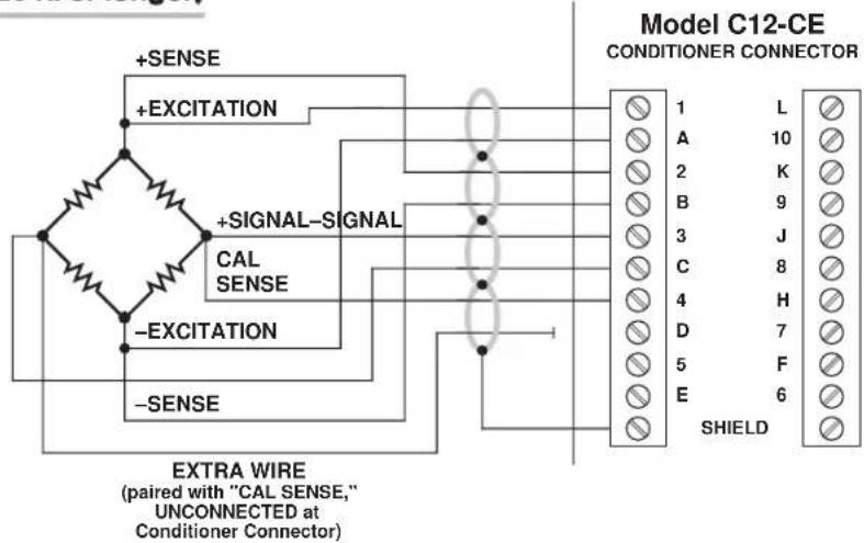
Fig. 2(c) 8-Wire Cabling to Lebow 1600 Series Transducer (ONLY)

Fig. 3 10A78 Signal Programming Jumper Pads and Shunt Calibration Resistor

3 SETUP AND/OR OPERATING CONSIDERATIONS
3.a PHASE AND SYMMETRY ADJUSTMENT FOR ALL TRANSDUCERS EXCEPT A LEBOW 1800 SERIES TRANSDUCER
Before you do a "two-point" or "shunt" calibration of your 10A78 for the first time, you should perform an initial "on-line" phase and symmetry adjustment. When using a Lebow 1800 Series Transducer (only), you should follow the special procedure given in the next section. For any other transducer, use the following procedure. ONCE SET FOR YOUR TRANSDUCER, THIS ADJUSTMENT NEED NOT BE REPEATED UNLESS A SIGNIFICANT CHANGE IN CABLE LENGTH OR CAPACITANCE IS REQUIRED.
a. You should first configure the 10A78 measurement channel—including a nominal "CALCULATED" CALIBRATION—as explained in Section 3.c, below. Be sure to download the configuration to the SPS6000 mainframe following the calibration.
b. Open the Configurator Software's On-Line Calibration window and step to a "live" display of the 10A78 channel (see Manual Section 3.e.2 for "Displaying Active Channels").
c. Remove the SPS6000 mainframe's front bezel (do NOT turn off the power).
d. Without removing the 10A78 from its slot, locate the PHASE AND SYMMETRY CONTROLS, which are accessible from the front of the card (see Fig. 4).
e. Load the transducer in the positive direction with a convenient "deadweight" value which is greater than one-half of full scale. Using a small insulated screwdriver,

Fig. 4 10A78 Phase and Symmetry Controls
adjust the 10A78's PHASE CONTROL until a maximum reading is obtained for the 10A78 channel.
f. Remove the transducer load.
g. Click on the Zero button in the On-Line Calibration window, and then on the Data button. Enter a value of "0" for the "zero" calibration value. Click Ok.
h. Now click on the +Shunt button in the On-Line Calibration window to switch in the 10A78's internal shunt resistor for a positive up-scale reading.
i. Record the reading you get.
j. Click on the +Shunt button once more, to open the positive shunt and turn "off" the button. Then click on the -Shunt button, to switch in the 10A78's internal shunt resistor for a negative reading.
k. Adjust the 10A78's SYMMETRY CONTROL until the negative value of the reading you recorded in Step i appears.
I. Click on the -Shunt button once more, to open the negative shunt and turn "off" the button.
m. You are now ready to perform “on-line calibration” of the 10A78 channel by either the “Two-Point (Deadweight)” or “Simulated (Shunt)” Calibration method (see Section 3.c, below).
3.b PHASE AND SYMMETRY ADJUSTMENT FOR A LEBOW 1800 SERIES TRANSDUCER
NOTE: WHEN USING THE 10A78 WITH A LEBOW 1800 SERIES TRANSDUCER, YOU SHOULD FIRST REPLACE THE 10A78'S INTERNAL 59K SHUNT RESISTOR WITH THE CALIBRATION RESISTOR SUPPLIED WITH THE TRANSDUCER.
a. Perform Steps a through d of the above procedure (Section 3.a).
b. Locate the "CAL/RUN" Switch in the cable harness of the 1800 Series transducer. Place this switch in the "CAL" position.
c. Establish a zero input for the 10A78 channel by removing all load from the 1800 Series transducer.
d. Click on the +Shunt button in the On-Line Calibration window to switch in the 10A78's internal shunt resistor for a positive up-scale reading.
e. Using a small insulated screwdriver, adjust the 10A78's PHASE CONTROL until a maximum reading is obtained for the channel.
f. Click on the +Shunt button once more, to open the positive shunt and turn "off" the button.
g. Now zero the reading of the 10A78 channel. Click on the Zero button in the On-Line Calibration window, and then on the Data button. Enter a value of "0" for the "zero" calibration value. Click Ok.
h. Close the channel's positive shunt once more via the +Shunt button, as in Step d, above.
i. You will now "force" the 10A78 channel to read the "EQUIVALENT INPUT" VALUE GIVEN BY THE TRANSDUCER MANUFACTURER FOR THE CALIBRATION RESISTOR YOU INSTALLED IN THE 10A78 (for a general discussion of EQUIVALENT INPUT, see Manual Section 3.e.7). With the +Shunt button still "on," click on the Data button in the On-Line Calibration window. Enter the "equivalent input" value for the "span" calibration point. Click Ok.
j. Click on the +Shunt button once more, to open the positive shunt and turn "off" the button.
k. Now click on the -Shunt button, to switch in the 10A78's internal shunt resistor for a negative reading.
I. Adjust the 10A78's SYMMETRY CONTROL to display the negative value of the same EQUIVALENT INPUT you entered in Step i (or some other specific negative engineering-unit value, if such a value is given by the transducer manufacturer for the calibration resistor).
m. Click on the -Shunt button once more, to open the negative shunt and turn "off" the button.
n. Move the transducer's "CAL/RUN" Switch to the "RUN" position.
o. Zero the 10A78 channel's reading once more, as you did in Step g, above.
p. Now apply the Save Online Changes command, as explained in Manual Section 3.e.4.
THE LEBOW 1800 / DAYTRONIC 10A78 SYSTEM IS NOW FULLY CALIBRATED. YOU NEED NOT PERFORM A SUBSEQUENT "DEADWEIGHT" OR "SIMULATED" CALIBRATION.
3.c CONFIGURATION AND CALIBRATION
For initial configuration of the ANALOG INPUT CHANNEL dedicated to a specific Model 10A78 card when used in SPS6000, see Manual Sections 3.a and 3.b.
CALCULATED CALIBRATION
In an SPS6000 system, a nominally accurate CALCULATED CALIBRATION should be initially applied to every Model 10A78 channel, even if you intend to perform additional "two-point" or "shunt" calibration (see Manual Sections 3.b and 3.e.5 for a general discussion of this calibration technique). To do so, you will enter an appropriate value for each of the following parameters in the channel's Input Configuration window:
- FILTERS: This setting is fixed at a cutoff frequency of 8.00 Hz, and cannot be changed.
• TRANSDUCER: The only presently available selection is STRAIN GAGE. - DESC: Enter here the desired engineering units in which the channel's final measurement value is to be expressed, as an alphanumeric string of up to four characters.
NOTE: The four following numbers will be automatically set to the highest precision that is presently displayable by the system, based on the currently entered full-scale transducer range and the system's full scale of "32767" for display A/D conversion.
Also note that the Configurator Software will display an appropriate error message if you try to enter a "Transducer" or "Output" value that is incompatible with one or more existing calibration settings. For example, it will not let you specify too much (or too little) input signal for the presently specified transducer full-scale range—or an output offset that lies outside the range allowed by previously entered calibration values.
• TRANSDUCER INFORMATION:
- FULL SCALE RANGE: Enter here the full-scale rating of the 10A78 channel's source transducer, expressed in the engineering units entered in the DESC field, as specified by the transducer manufacturer. NOTE: If you attempt to enter a value of full-scale range that yields either not enough or too much input signal for the card type, the software will ask you whether you want the transducer full-scale range and the full-scale output to be set equal (you may answer Ok or Cancel).
- FULL SCALE OUTPUT (ELECTRICAL UNITS): Enter here the full-scale output of the 10A78 channel's source transducer, expressed in mV/V, as specified by the transducer manufacturer.
• OUTPUT INFORMATION:
- FULL SCALE OUTPUT ([specified units]): Enter here the desired full-scale measurement (to be represented by a full-scale analog output of 10 V-DC), expressed in the engineering units entered in the DESC field.
- OFFSET ([specified units]): Enter here the desired zero offset to be applied to the 10A78 channel's measurement reading, expressed in the engineering units entered in the DESC field.
Remember that CALCULATED CALIBRATION will not go into effect until the configuration that contains the user-entered calibration values is downloaded to the SPS6000 system via the procedure given in Manual Section 3.c.4.
TWO-POINT (DEADWEIGHT) CALIBRATION
If a 10A78 channel's initial software-calculated calibration does not yield sufficient accuracy—or if the full-scale "mV/V" rating of the strain gage transducer is unknown—additional calibration can be performed "on-line," using the Configurator Software's On-Line Calibration window or the system's front-panel display/keypad. Manual Section 3.e.6 gives general instructions for this conventional "zero and span" calibration technique.
If you want to permanently save the scaling and offset values established during deadweight calibration, be sure to apply a SAVE ONLINE CHANGES command as soon as calibration is complete (see Manual Section 3.e.4).
NOTE: Calibrated Full Scale Output (Electrical Units) and Calibrated Offset values are displayed in a 10A78 channel's Input Configuration window. Initially, these "calibrated" values will be the same as the last user-entered Full Scale Output and Offset values to have been downloaded to the SPS6000. However, as soon as a "zero" calibration point is entered during on-line calibration of this channel, the "calibrated" zero offset of the output signal is automatically determined and applied by the system. As soon as a "span" calibration point is entered during on-line calibration, the "calibrated" electrical output of the source transducer is automatically determined and applied, in order to achieve the desired scaling. The displayed Calibrated Full Scale Output then represents the actual value of full-scale transducer output (in electrical units) currently in effect within the SPS6000 system, while the displayed Calibrated Offset represents the actual output offset currently in effect, in the specified engineer-
ing units. For a properly calibrated channel, there should be little difference between the actual "calibrated" output/offset values and the respective stored values—i.e., the last user-entered output/offset values to have been downloaded to the SPS6000. Ideally, the two values should be equal.
SIMULATED (SHUNT) CALIBRATION
This is a convenient “shunt resistor” method, especially when overall deadweight calibration is impractical.* Here the second (“span”) input is not produced by loading the source transducer, but by “simulating” a particular up-scale value of mechanical input. This known EQUIVALENT INPUT then serves to determine the SCALING FACTOR for the channel.
Like deadweight calibration, shunt calibration can be performed "on-line," using the Configurator Software's On-Line Calibration window or the system's front-panel display/keypad. You should refer to Manual Section 3.e.7 for general theory and instructions on this standard "shunt cal" technique.
If you want to permanently save the scaling and offset values established during deadweight calibration, be sure to apply a SAVE ONLINE CHANGES command as soon as calibration is complete (see Manual Section 3.e.4).
The 10A78 is equipped with a 59-kΩ, 0.1% calibration resistor, located on turret terminals at the rear of the card (see Fig. 3). You may, if you wish, replace the installed 59K shunt resistor with a resistor of another value (strain-gage transducer manufacturers often supply such resistors with their instruments).
Manual Section 3.e.7 explains how a 10A72-2C channel's shunt resistor may be easily switched in and out by means of the +SHUNT or -SHUNT button on the SPS6000 unit's front-panel display/keypad or in the Configurator Software's On-Line Calibration window. If you wish to control the shunt calibration process by means of logic-level inputs through the 10A78's rear I/O CONNECTOR—a standard feature of certain other Daytronic strain gage conditioner cards—you will require a specially modified version of the 10A78 (contact the factory for details).
WITH OPTIONAL CONNECTOR
FOR FULL COMPLIANCE WITH

STANDARDS WHEN USED
IN AN SPS6000 SYSTEM
MODEL 10A96
AMPLIFIED ACCELEROMETER
VIBRATION CONDITIONER CARD
1 GENERAL DESCRIPTION AND SPECIFICATIONS
The single-channel Model 10A96 measures the true RMS value of the vibratory component of the output signal of an Amplified Piezoelectric Accelerometer, for which an excitation of ± 15 V-DC is provided. It is ideal for any number of applications where the accurate monitoring of vibration is critical—as, for example, in the testing of motors, gear-boxes, pumps, engines, conveyors, fans, and compressors.
The 10A96 yields two “subchannels,” with corresponding analog outputs to wire-wrap pins:
- Subchannel No. 1: VIBRATORY COMPONENT (RMS)
- Subchannel No. 2*: AVERAGE ACCELERATION
* PLEASE NOTE:
10A96 Subchannel
No. 2 cannot presently
be used when the
card operates in the
SPS6000 System.
The 10A96's "front-end" amplifier gain is user-selectable, which allows the card to accept accelerometer signals from ± 50mV to ± 5V . The card also features a 10-Hz high-pass filter with selectable gain, followed by a band-pass filter with selectable upper cut-off frequencies. It can thus be configured for specific test or process conditions such as operating frequency or RPM, expected vibration amplitude, etc. (see Section 3, below).
In SPS6000, the 10A96 employs “calculated” calibration involving entry of the sensitivity rating of the channel’s transducer in units of “mV/g (RMS)”—as specified by the accelerometer manufacturer—as well as the nominal full-scale rating in RMS units of “g”—as specified by the manufacturer.
ADDITIONAL 10A96 SPECIFICATIONS
Input Range: User-selectable gain accommodates accelerometer signal from ±50
mV to ±5 V, full scale; for “type” codes assigned to 10A96 data channels on the basis of desired pass-band cutoff frequency, see Appendix A of the latest Daytronic Conditioner Cards Catalog
Excitation: Fixed ±15 V-DC nominal; 15 mA, maximum
Amplifier:
Normal-Mode and Common-Mode Range: ±5 V operating; ±7 V without instrument damage
Common-Mode Rejection Ratio: DC: -60 dB; at 60 Hz and 1 kHz: -50 dB
Input Impedance (Differential and Common-Mode): 10^8 MΩ and 5-nanoamp bias current; for special analog filtering provisions, see the Filters specification, below
(cont'd)
Offset: Initial: ±0.2% of full scale; vs. Temperature: ±50 ppm/°C
Gain Accuracy*: ±0.02% of full scale typical, following calibration
Gain Stability (center of chosen passband): vs. Temperature: ±100 ppm/°C
Filter:
1) LOW-PASS: 3-pole modified Butterworth; 3 dB down at 10 Hz; 60 dB down at 100 Hz
Step Response Settling Time (Full-Scale Output):
To 1% of final value: 100 msec
To 0.1% of final value: 150 msec
To 0.02% of final value: 600 msec
2) BAND-PASS: Selectable upper cut-off frequency for each subchannel: 20, 40, 80, 125, 250, 500, 1000, or 1600 Hz
3) HIGH-PASS: 10 Hz, with selectable gain of 1, 2, 5, 10, or 20
Auxiliary Outputs: Filtered output for RMS vibration frequency available as input to an Analog Signal Processor Card
2 TRANSDUCER CONNECTIONS
IMPORTANT
The type of I/O CONNECTOR to be used with the Model 10A96 will depend on whether or not you wish your SPS6000 system to comply with CE standards.
If CE compliance is NOT required, you may use the "conventional" connector that comes with the 10A96 card. If CE compliance is required, you MUST use the Model C12-CE Conditioner Connector, which is ordered separately from the 10A96 card. Both "conventional" and "CE-compliant" connectors are fully described in Manual Section 2.b.3.
ALSO NOTE: CE COMPLIANCE FURTHER REQUIRES THE CABLE SHIELDING SHOWN IN FIG. 2. For more information on the “CONNECTION OF CABLE SHIELD,” see Manual Section 2.b.3.
5-wire connections to a Daytronic Model ACL3 Amplified Piezoelectric Accelerometer are given in Fig. 1 for “conventional” cabling using the standard Daytronic 60322 connector, and in Fig. 2 for CE-compliant cabling using the Model C12-CE. The 10A96 will work with any similar instrument with a sensitivity of 50.0 mV/g, using similar cable connections. Note that for “conventional” cabling (ONLY), a 5-wire cable with a single shield could be used, if desired, instead of the individually shielded pairs shown in Fig. 1. Table 1 gives standard pin or terminal assignments for the 10A96 I/O connector (“conventional” or “CE-compliant,” respectively).
Table 1 Model 10A96 Pin/Terminal Assignments
I/O Connector Conditioner
Pin/Terminal Line
Number Function
1 +15 V-DC EXCITATION
A -15 V-DC EXCITATION
2,B Not Committed
3 + SIGNAL
C - SIGNAL
* Initial (uncalibrated) inaccuracy may be as great as ±1.0% of full scale. Maximum error that could occur upon replacement of a Model 10A96 not followed by calibration is ±2% of full scale.
4,D,5 Not Committed
E SIGNAL COMMON
6 Not Committed
F FILTERED OUTPUT
All Other Pins Not Committed

Fig. 1 Model 10A96
"CONVENTIONAL" Transducer Cabling
Connector pins shown as viewed from rear (cable) side of connector Ground Lug

Fig. 2 Model 10A96
CE-COMPLIANT Transducer Cabling
Fig. 3 10A96 Amplifier and Filter Gain Selection Jumper Pins
"Front-End" Amplifier Gain Selection Jumper Pins

High-Pass Filter Gain Selection Jumper Pins
Fig. 4
10A96 Front-End Amplifier Gain
Selection Jumper Pins


Fig. 5
10A96 Filter Gain
Selection Jumper Pins
SETUP AND/OR OPERATING CONSIDERATIONS
IMPORTANT
The value of FRONT-END AMPLIFIER GAIN and the value of HIGH-PASS FILTER GAIN to which your 10A96 card is to be set will be indicated in the 10A96 channel's Input Configuration window after all other configuration/calibration parameters have been entered in that window (as explained in Section 3.d, below). FOR PROPER OPERATION OF THE CARD, IT IS ABSOLUTELY NECESSARY THAT YOU SET THE 10A96'S INTERNAL PROGRAMMING JUMPERS FOR THE GAIN VALUES SHOWN IN THE INPUT CONFIGURATION WINDOW, per the instructions given in the following two sections.
3.a SETTING FRONT-END AMPLIFIER GAIN
- Remove the 10A96 card from its mainframe slot. For "Card Insertion and Removal," see Manual Section 2.b.1.
- Locate the FRONT-END AMPLIFIER GAIN SELECTION JUMPER PINS shown in Fig. 3. One "minijumper" is provided for interconnecting any two vertically adjacent jumper pins.
- Position the jumper as shown in Fig. 4 to set the gain to the "Front-End Amplifier" value displayed in the 10A96 channel's Input Configuration window after all other configuration/calibration parameters have been properly entered (as explained in Section 3.d, below).
- Do not reinstall the 10A96 card until you have set the high-pass filter gain (next section).
3.b SETTING HIGH-PASS FILTER GAIN
- Locate the HIGH-PASS FILTER GAIN SELECTION JUMPER PINS shown in Fig. 3. One "minijumper" is provided for interconnecting any two vertically adjacent jumper pins.
- Position the jumper as shown in Fig. 5 to set the gain to the "High-Pass Filter" value displayed in the 10A96 channel's Input Configuration window after all other configuration/calibration parameters have been properly entered (as explained in Section 3.d, below).
- Reinsert the 10A96 card in its mainframe slot.
3.c SETTING BAND-PASS FILTER CUTOFF FREQUENCY
In SPS6000, you will set the upper cutoff frequency of the 10A96's band-pass filter by selecting the corresponding range value for the F.S. Output field (under "OUTPUT INFORMATION") in the 10A96 channel's Input Configuration window—see the following section. You may choose any of the following ranges: 10-20 Hz; 10-40 Hz; 10-80 Hz; 10-125 Hz; 10-250 Hz; 10-500 Hz; 10-1000 Hz; and 10-1600 Hz.
3.d CONFIGURATION AND CALIBRATION
For initial configuration of the ANALOG INPUT CHANNEL dedicated to a specific Model 10A96 card when used in SPS6000, see Manual Sections 3.a and 3.b.
In SPS6000, "CALCULATED" CALIBRATION is normally the only calibration method applied to a 10A96 channel (see Manual Sections 3.b and 3.e.5 for a general discussion of this calibration technique).
CALCULATED CALIBRATION
Enter an appropriate value for each of the following parameters in the channel's Input Configuration window*:
- FILTERS: This setting is fixed at a cutoff frequency of 10.00 Hz, and cannot be changed.
- EXCITATION VOLTAGE: This setting is fixed at "15 VOLT," and cannot be changed.
NOTE: The two following numbers will be automatically set to the highest precision that is presently displayable by the system, based on the currently entered full-scale transducer range and the system's full scale of "32767" for display A/D conversion.
Also note that the Configurator Software will display an appropriate error message if you try to enter a "Transducer" or "Output" value that is incompatible with one or more existing calibration settings. For example, it will not let you specify too much (or too little) input signal for the presently specified transducer full-scale range—or an output offset that lies outside the range allowed by previously entered calibration values.
• TRANSDUCER INFORMATION:
- FULL-SCALE RANGE: Enter here the nominal full-scale rating of the channel's transducer, in RMS units of "g," as specified by the accelerometer manufacturer ("g" is the earth's gravitational constant—approximately 32 ft/sec ^2 or 9.80 m/sec ^2 ).* NOTE: If the transducer datasheet gives a full-scale range in peak g's, divide this value by 1.4142 to get RMS.
For example, if you were using as your source transducer the Daytronic Model ACL3 Amplified Piezoelectric Accelerometer (which is rated at a full-scale output of ±5 V (peak)), you would enter for “FULL-SCALE RANGE” a value of 70.70 (g, RMS).
- TRANSDUCER OUTPUT: Enter here the sensitivity rating of the channel's transducer, in units of "mV/g (RMS)" as specified by the accelerometer manufacturer. NOTE: Do not divide the stated sensitivity by 1.4142, even if you did so to convert the transducer's full-scale range from peak g's to RMS g's.
For example, if you were using the Model ACL3, you would enter for "TRANS-DUCER OUTPUT" a value of 50.00 (mV/g, RMS).
• OUTPUT INFORMATION:
- F.S. OUTPUT (G) IN THE RANGE OF
- For the first field, select from the popup list the desired output range (i.e., bandwidth) for the 10A96 channel, the upper value of each range being the upper cutoff frequency of the 10A96's band-pass filter (see Section 3.d, above).
- In the second field, enter the desired full-scale measurement (to be represented by a full-scale analog output of 10 V-DC), expressed in RMS g's (for example, 5.00 (g, RMS)).
NOTE: The reading of a 10A96 channel will normally be very close to zero when NO VIBRATION is present. If it is not less than 0.5% of full scale, a problem usually exists. Improper shielding and EMI from industrial heaters, motors, etc., are the most common sources of error.
- OFFSET, RESIDUAL (G): Enter here the residual zero offset to be applied to the 10A96 channel's measurement reading, expressed in RMS g's, to cancel any remaining small offset.
NOTE: If there is a significant nonzero offset in your 10A96 channel's data reading, you may use "on-line" zeroing to remove some or all of it, before entering the OFFSET, RESIDUAL value in the Input Configuration window. Using the Zero button on the front of the SPS6000 unit or in the Configurator Software's On-Line Calibration window, you should perform the first ("zero point") half of the standard "TWO-POINT (DEADWEIGHT)" calibration procedure given as Step b in Manual Section 3.e.6. Do the "zero point" procedure ONLY; do not attempt to "span" the channel reading.
Remember that CALCULATED CALIBRATION will not go into effect until the configuration that contains the user-entered calibration values is downloaded to the SPS6000 system via the procedure given in Manual Section 3.c.4.
NOTE: Calibrated Transducer Output and Calibrated Offset (Residual) values are displayed in a 10A78 channel's Input Configuration window. Initially, these "calibrated" values will be the same as the last user-entered Transducer Output and Offset values to have been downloaded to the SPS6000. However, if a "zero" calibration point is entered "on-line" (as explained above), the "calibrated" zero offset of the output signal is automatically determined and applied by the system. The displayed Calibrated Offset then represents the actual output offset currently in effect, in the specified engineering units. For a properly calibrated channel, there should be little difference between the actual "calibrated" offset value and the respective stored value—i.e., the last user-entered offset value to have been downloaded to the SPS6000. Ideally, the two values should be equal.
WITH OPTIONAL CONNECTOR FOR FULL COMPLIANCE WITH

STANDARDS WHEN USED IN AN SPS6000 SYSTEM
MODEL AA14-4F010
THERMOCOUPLE
CONDITIONER CARD
1 GENERAL DESCRIPTION AND SPECIFICATIONS
The AA14-4F010 is a high-isolation, four-channel conditioner, accepting real-world temperature signals from Types E, J, K, N, R, S, and T Thermocouples. Based on NIST polynomials, linear output is produced over each thermocouple's stated operating range, and within the rated accuracy limits—without the need for additional output processing. See Table 1 for the "mV/degree" linear output produced by the AA14-4F010 for different TC types and ranges (°C or °F).
PLEASE NOTE: WHILE ALL FOUR CHANNELS OF A GIVEN AA14-4F010 CARD MUST BE DEDICATED TO THE SAME TC TYPE, INDIVIDUAL CARDS DEDICATED TO DIFFERENT TC TYPES MAY BE MIXED AS DESIRED WITHIN THE TOTAL DATA ACQUISITION SYSTEM. IT IS ALSO REQUIRED THAT THE AA14-4F010'S CHANNEL NO. 1 BE USED.
This conditioner features true galvanic isolation with pulse-width modulation, allowing sensor-to-chassis or sensor-to-sensor common-mode voltages as high as 1500 V (rms) to be accommodated. Internal reference-junction compensation is automatically selected by thermocouple choice. No external cold junction is required (although the user may supply his own Controlled Ambient Temperature Zone for reference-junction purposes, if desired). A “CONVENTIONAL” four-channel isothermal connector assembly (Daytronic No. 60323, shown in Figs. 2 and 4) is supplied with each Model AA14-4F010, with screw terminals for direct connection of TC leads (which cannot be soldered), and with a precision thermistor for measurement of the reference-junction temperature. The same connector may be used with any TC type.
If compliance with CE STANDARDS is desired, however, a Model CAA14-CE Conditioner Connector (shown in Figs. 3 and 5) MUST be used in place of the "conventional" 60323 connector. The CAA14-CE is ordered separately from the AA14-4F010 and, like the 60323, may be used with any TC type.
In the event of a broken thermocouple wire or other “open TC” condition, the AA14-4F010 will automatically report an indeterminate off-scale reading for the TC channel in question, with positive or negative polarity selectable on a per-channel basis (as explained in Section 3.a).
Each AA14-4F010 input channel employs an active low-pass filter with a fixed cutoff frequency of 10 Hz. A nominal ±5-V ANALOG OUTPUT is produced by each active AA14-4F010 input channel, for purposes of real-time signal monitoring. Each of these "Auxiliary Outputs" can be used as input to an Analog Signal Processor (ASP) Card. Each output may be individually set, if desired, to represent the prefiltered value of the corresponding input (see Section 3.b).
A simple “calculated” calibration procedure lets you quickly set up each TC-based data channel by entering appropriate “type” and scaling information. During operation, appropriate reference-junction compensation, real-time digital linearization, and engineering-unit scaling are automatically applied for each type of thermocouple
used. A second, two-point "zero and span" calibration technique is provided, however, for applications where it is desirable to force multiple TC readings to the same exactly known temperature.*
Fig. 1 Model AA14-4F010 Modular Card Components
I/O Connector
Four-Channel Isolator Tile
Fixed 10-Hz Filter (Chans. 3 & 4)
Fixed 10-Hz Filter (Chans. 1 & 2)
NOTE: Fig. 1 shows the stand-off circuit boards (or "tiles") that provide the analog filtering and galvanic isolation for an AA14-4F010 card's data channels. FILTER TILES (ONLY) MAY BE INSTALLED OR REMOVED BY THE USER, IN THE FIELD. CONTACT THE DAYTRONIC SERVICE DEPARTMENT FOR COMPLETE INSTRUCTIONS.
ADDITIONAL AA14-4F010 SPECIFICATIONS
Number of Input Channels: Four
Thermocouple Types and Ranges: See Table 1; automatically selected—on an individual channel basis—when the channel is configured; for "type" codes assigned to AA14-4F010 data channels, see Appendix A of the latest Daytronic Conditioner Cards Catalog
Amplifier (per channel):
Normal-Mode Range: ±80 mV operating; ±240 V without instrument damage Common-Mode Range: 1200 V (rms) operating and without instrument damage
Common-Mode Rejection Ratio: DC and at 60 Hz: -130 dB
Input Impedance: Differential: 10 MΩ; Common-Mode: 470 pF to earth
Offset: Initial: ±10 μV; vs. temperature: ±0.2 μV/°C; vs. time: ±0.5 μV/month
Gain Accuracy: ±0.05% of full scale
Gain Stability: vs. temperature: ±25 ppm/°C; vs. time: ±20 ppm/month
Filter (per channel): 3-pole modified Butterworth, 3 dB down at 10 Hz; 60 dB down at 195 Hz
Step-Response Settling Time (Full-Scale Output):
To 1% of final value: 70 msec
To 0.1% of final value: 85 msec
o 0.02% of final value: 95 msec
Auxiliary Outputs: Nominal ±5 V-DC signals available as input to an Analog Signal Processor Card; individually jumper-selectable to represent either the filtered or prefiltered value of the channel (see Section 3.b)
Power-Supply Slot Allotment: Maximum consumption of supply current from the Conditioner Card Slot is 95 mA
Table 1 Thermocouple Ranges for the Model AA14-4F010
| TC Type Range Resolution (mV/degree)* | Typical Daytronic Linear System Display Output | |
| E -200°C to +1000°C 0.1°C 5.0000 | ||
| E -328°F to +1832°F 0.1°F 2.7778 | ||
| J -200°C to +1200°C 0.1°C 4.0000 | ||
| J -328°F to +2192°F 0.1°F 2.2222 | ||
| K -200°C to +1372°C 0.1°C 4.0000 | ||
| K -328°F to +2501.6°F 0.1°F 2.2222 | ||
| N | -180°C to +1300°C 0.1°C 4.0000 | |
| N | -292°F to +2372°F 0.1°F 2.2222 | |
| R | -50°C to +1768°C | 0.1°C 2.0000 |
| R -58°F to +3214.4°F | 0.1°F 1.1111 | |
| S | -50°C to +1768°C | 0.1°C 2.0000 |
| S -58°F to +3214.4°F | 0.1°F 1.1111 | |
| T | -200°C to +400°C | 0.1°C 5.0000 |
| T -328°F to +752°F | 0.1°F 2.7778 | |
2 TRANSDUCER CONNECTIONS
IMPORTANT
The type of I/O CONNECTOR to be used with the Model AA14-4F010 will depend on whether or not you wish your SPS6000 system to comply with CE standards.
If CE compliance is NOT required, you may use the “conventional” connector that comes with the AA14-4F010 card. This is the standard Daytronic 60323 four-channel isothermal connector shown in Figs. 2 and 4.
If CE compliance is required, you MUST use the Model CAA14-CE Conditioner Connector, shown in Figs. 3 and 5, which is ordered separately from the AA14-4F010 card.
ALSO NOTE: CE COMPLIANCE FURTHER REQUIRES THE CABLE SHIELDING
SHOWN IN FIG. 5. For more information on the “CONNECTION OF CABLE SHIELD,” see Manual Section 2.b.3.
Connection of thermocouple leads is given in Fig. 4 for “conventional” cabling using the standard Daytronic 60323 connector, and in Fig. 5 for CE-compliant cabling using the Model CAA14-CE. Each connector contains four “±” screw-terminal pairs, one for each TC sensor. TC leads should be directly attached to the corresponding screw terminals (they should never be soldered). Each screw terminal connects internally to a specific pin on the AA14-4F010's rear 20-pin I/O CONNECTOR. Table 2 gives standard pin assignments for the I/O connector.
Since reference-junction compensation is provided by the dual-bead thermistor embedded in the Conditioner Connector, no external cold junction is required.
IMPORTANT: UNUSED THERMOCOUPLE INPUT CHANNELS should be shorted together as shown in Fig. 6 (which applies to both “conventional” and CE-compliant cabling). This is to prevent possible crosstalk from the “OPEN TC” detection circuit into working TC channels.
Fig. 2 "CONVENTIONAL" Four-Channel Thermocouple Connector Assembly (No. 60323)


Table 2 Model AA14-4F010 Pin Assignments
| I/O Connector Conditioner Conditioner Pin Screw Channel Line Number Terminal Number Function | ||
| 1 1(+) 1 +SIGNAL | ||
| A 1(-) 1 -SIGNAL | ||
| 2 Not Committed | ||
| B | Not Committed | |
| 3 3(+) 2 +SIGNAL | ||
| C 3(-) 2 -SIGNAL | ||
| 4 Not Committed | ||
| D | Not Committed | |
| 5 5(+) 3 +SIGNAL | ||
| E | 5(-) 3 -SIGNAL | |
| 6 Not Committed | ||
| F Not Committed | ||
| 7 7(+) 4 +SIGNAL | ||
| H 7(-) 4 -SIGNAL | ||
| 8 Not Committed | ||
| J | Not Committed | |
| 9 INTERNAL | THERMISTOR: T1 | |
| K,L | USE | THERMISTOR: GROUND (COMMON) |
| 10 | ONLY | THERMISTOR: T2 |

3
SETUP AND/OR OPERATING CONSIDERATIONS
3.a SELECTION OF "OPEN TC" POLARITY
In the event of a broken thermocouple wire or other “open TC” condition, the Model AA14-4F010 will automatically report an indeterminate off-scale reading for the TC channel in question. The conditioner is normally preset at the factory for positive off-scale “open TC” indication for each channel. However, you may easily reset any channel for negative off-scale “open TC” indication, as follows:
- Remove the AA14-4F010 card from its mainframe slot. For "Card Insertion and Removal," see Manual Section 2.b.1.
- Refer to Fig. 7, below, and locate the OPEN TC POLARITY PROGRAMMING JUMPER PINS on the top side of the Isolator Tile. One "minijumper" is provided for each channel's set of three jumper pins.
Fig. 7 Model AA14-4F010 Programming Jumper Pins

- Position the jumper for each channel as shown in Fig. 7 to interconnect the pair of pins corresponding to the desired "open TC" polarity for that channel. You will need to use a small pair of needle-nosed pliers to move the jumper.
- Reinsert the AA14-4F010 card in its mainframe slot.
3.b SELECTION OF ANALOG OUTPUT MODES
As mentioned in Section 1, each AA14-4F010 channel's ±5-V ANALOG OUTPUT can be set to represent either the filtered or prefiltered reading of that channel. To set the output mode for each of your AA14-4F010's active input channels, ^* you should
- Remove the AA14-4F010 card from its slot (see Section 3.a, Step 1, above).
- Refer to Fig. 7 and locate the OUTPUT MODE PROGRAMMING JUMPER PINS beneath the AA14-4F010's Filter Tile(s). One "minijumper" is provided for each channel's set of three jumper pins.
- Position the jumper for each channel as shown in Fig. 7 to interconnect the pair of pins that corresponds to the desired output mode for that channel. You will need to use a small pair of needle-nosed pliers to move the jumper.
- Reinsert the AA14-4F010 card in its mainframe slot.
3.c CONFIGURATION AND CALIBRATION
For initial configuration of ANALOG INPUT CHANNELS dedicated to a specific Model AA14-4F010 card when used in SPS6000, see Manual Sections 3.a and 3.b. REMEMBER THAT THE AA14-4F010'S CHANNEL NO. 1 MUST ALWAYS BE USED.
CALCULATED CALIBRATION
In an SPS6000 system, a nominally accurate CALCULATED CALIBRATION should be initially applied to every Model AA14-4F010 channel, even if you intend to perform additional "two-point" calibration (see Manual Sections 3.b and 3.e.5 for a general discussion of this calibration technique). To do so, you will enter an appropriate value for each of the following parameters in the channel's Input Configuration window:
- FILTERS: THIS FIELD DOES NOT APPLY TO AN AA14-4F010 CHANNEL, WHICH HAS A FIXED ANALOG-FILTER CUTOFF FREQUENCY OF 10 HZ.**
- THERMOCOUPLE TYPE: Select from the popup list the thermocouple type of the channel's source transducer. REMEMBER THAT THIS TYPE MUST BE THE SAME FOR ALL FOUR CHANNELS.
- UNITS: Select from the popup list the desired engineering units in which the channel's final measurement value is to be expressed (Celsius or Fahrenheit). Note that when you change the existing units, the current "Output Information" entries will be set back to default values.
* The output mode setting for an UNUSED channel is immaterial, and will not affect operation of the AA14-4F010.
** By pressing the DOWN ARROW to the right of the FILTERS field, you can display a list of the standard "F1" filter settings for an "AA" card with programmable filtering. However, changing the frequency value displayed in the FILTERS field will have no effect on the AA14-4F010 configuration.
• TRANSDUCER INFORMATION:
- TEMPERATURE RANGE ([degrees C or F]): The allowable values for entry in this field will depend on the thermocouple type selected above. Select here the desired upper limit of the specified TC's temperature range, in the specified units. Note that for Types E, J, K, N, and T thermocouples, a restricted high-resolution range is available for both °C and °F.
The lower limit of the selected range will be automatically displayed in the LOWEST VALUE field (which cannot be edited by the operator).
• OUTPUT INFORMATION:
- FULL SCALE OUTPUT ([degrees C or F]): The value displayed in this field will automatically default to the maximum output (in the specified engineering units) allowed by the currently specified temperature range. You may enter another (lower) value of desired full-scale °C or °F measurement for this channel—to be represented by a full-scale analog output of 10 V-DC—as long as this value is within the allowed range (the software will alert you if it is not).
- OFFSET ([degrees C or F]): The value displayed in this field will automatically default to "0.0" or "0.00" (if units of degrees Celsius have been selected) or to "32.0" or "32.00" (if units of degrees Fahrenheit have been selected). You may enter here another value of desired zero offset for this channel (in the specified temperature units). For example, to obtain a measurement reading in degrees Kelvin (°K) for a channel with selected units of degrees C, you would enter an offset of "273.2" (or "273.20"), instead of "0.0" (or "0.00"). NOTE: The software will not let you enter an offset outside the allowed range.
Remember that CALCULATED CALIBRATION will not go into effect until the configuration that contains the user-entered calibration values is downloaded to the SPS6000 system via the procedure given in Manual Section 3.c.4.
TWO-POINT (DEADWEIGHT) CALIBRATION
If a AA14-4F010 channel's initial software-calculated calibration does not yield sufficient accuracy, additional "two-point" calibration can be performed on a real-time basis, using the Configurator Software's On-Line Calibration window or the system's front-panel display/keypad—but only when independently and accurately known temperature references are available (preferably the high and low extremes to which the sensor will be subjected). Manual Section 3.e.6 gives general instructions for this conventional "zero and span" calibration technique.
If you want to permanently save the scaling and offset values established during deadweight calibration, be sure to apply a SAVE ONLINE CHANGES command as soon as calibration is complete (see Manual Section 3.e.4).
NOTE: Following “on-line” deadweight calibration of a AA14-4F010 channel, the channel’s Input Configuration window may display a non-zero Calibrated Deviation value for “Transducer Information” and/or “Offset.” As soon as a “span” calibration point is entered during on-line calibration, the “calibrated” full-scale electrical output of the source transducer is automatically determined and applied by the system in order to achieve the desired scaling. The Calibrated Deviation displayed in the “Transducer Information” portion of the window is the percentage of difference between the full-scale transducer output (in electrical units) derived from the last user-entered Temperature Range value to have been downloaded to the SPS6000 and the full-scale transducer output (in electrical units) currently in effect within the SPS6000 system as a result of the last on-line calibration. For a properly calibrated channel, this
percentage should be small (ideally, it should be zero). The "Offset" Calibrated Deviation displayed in the "Output Information" portion of the window is similarly the percentage of difference between the last user-entered zero offset value to have been downloaded to the SPS6000 and the offset that is actually in effect within the SPS6000 system as a result of the last on-line "deadweight" calibration.
4 DIAGNOSTIC WIRE-WRAP PINS
As a special diagnostic and service tool, the five pins shown in Fig. 8 are directly accessible from the front of an installed AA14-4F010 card. These pins allow voltmeter or oscilloscope observation of data-channel output signals. THEIR USE IS INTENDED PRIMARILY FOR TRAINED SERVICE TECHNICIANS. With regard to the on-board diagnostic pins, please note the following:
- PROPER ESD PRACTICE SHOULD BE OBSERVED WHEN MAKING CONTACT WITH AN AA14-4F010 BOARD INSTALLED IN A "LIVE" DAYTRONIC SYSTEM MAINFRAME. ALWAYS GROUND YOURSELF TO THE MAINFRAME CHASSIS BEFORE TOUCHING THE BOARD.
- THE ANALOG SIGNAL PRESENT AT EACH ACTIVE "CHANNEL" PIN REPRESENTS EIGHT TENTHS (0.8) OF THAT CHANNEL'S NOMINAL CALL-BUS VOLTAGE. For a channel delivering a standard full-scale (+5-V) output, the corresponding diagnostic pin will therefore register +4 V.
- THE ANALOG SIGNAL PRESENT AT EACH ACTIVE "CHANNEL" PIN REPRESENTS THE FILTERED CHANNEL OUTPUT, AND IS NOT AFFECTED BY THE ANALOG OUTPUT MODE CURRENTLY SELECTED FOR THAT CHANNEL (see Section 3.b).
- THE "SLOT CALL" PIN DELIVERS A LOGIC SIGNAL THAT MAY BE USED TO SYNCHRONIZE AN OSCILLOSCOPE FOR TIMING ANALYSIS OF THE AA14-4F010 CARD.
Fig. 8 Diagnostic Wire-Wrap Pins

WITH OPTIONAL CONNECTOR
FOR FULL COMPLIANCE WITH

STANDARDS WHEN USED IN AN SPS6000 SYSTEM
MODEL AA30-4
LVDT
CONDITIONER CARD
1 GENERAL DESCRIPTION AND SPECIFICATIONS
The AA30-4 is a four-channel conditioner for measurement of displacement, force, pressure, and other parameters obtained with a linear variable differential transformer (LVDT) or variable reluctance transducer.
Based on the synchronous carrier-demodulator principle, the AA30-4 supplies regulated, remotely sensed AC excitation for each active transducer channel—thus allowing direct measurement of thickness (when two separate inputs are summed) or of taper (when their difference is calculated). It then demodulates, filters, and amplifies the resulting signals to produce system outputs precisely proportional to LVDT core displacement. The AA30-4 automatically adjusts to the signal phase shift of the transducer in use, thereby insuring optimum sensitivity and linearity.
Unlike the Model 10A30-2C or 10A31-4, the Model AA30-4 does not require special cabling to accommodate "long-stroke" LVDT's (full-scale range of ±1 inch or greater). Also, the AA30-4's enhanced linearity correction lets it accommodate a wider range of displacement transducers.
Like most Daytronic "Advanced Analog" ("AA") cards, the AA30-4 features optional PROGRAMMABLE LOW-PASS ACTIVE FILTERING for the removal of unwanted high-frequency measurement-signal components. Selectable analog filtering is offered for the AA30-4 from 0.2 through 200 Hz in 16 steps—or, if desired, a fixed filter of either 10 or 50 Hz for all channels may be specified at the time of order. When the AA30-4 is used in the SPS6000 System, its per-channel analog filter settings are normally made via the standard Configurator Software or—on a "run-time" basis only—via the SPS6000 unit's front-panel Filter button.
A nominal ±5-V ANALOG OUTPUT is produced by each active AA30-4 input channel, for purposes of real-time signal monitoring. Each of these “Auxiliary Outputs” can be used as input to an Analog Signal Processor (ASP) Card. Each output may be individually set, if desired, to represent the prefiltered value of the corresponding input.*
Separate excitation for each channel uses remote sensing of excitation voltage and is slaved to a common System Reference Voltage. The result is consistently stable ratio-metric measurement, unaffected by possible power-supply drift. A "Slave Excitation" input is available if the user wishes to provide an external excitation voltage and frequency instead of the AA30-4's internal supply.**
* In the case of the Model AA30-4, an active 300-Hz filter is applied to each input channel as part of the standard signal demodulation process, prior to delivery of the signal either to an installed filter tile or to a wire-wrap pin. See “Specifications” for response characteristics of the “prefiltered” AA30-4 output.
** The external excitation input must be 2 to 3.5 V-AC (rms) and 2 to 6 kHz, referenced to "center wire" (Signal Common). See Section 3.a for details.
The AA30-4 is manufactured using the latest surface-mount technology, resulting in the highest immunity to shock and vibration. As explained in Section 2, I/O connections are via secure, clearly labelled screw terminals in a special AA30-4 CONNECTOR ASSEMBLY. A “CONVENTIONAL” connector (shown in Fig. 2) is supplied with each Model AA30-4, with screw terminals for direct connection of transducer leads.
If compliance with CE STANDARDS is desired, however, a Model CAA30-CE Conditioner Connector MUST be used in place of the “conventional” connector. Very similar in form to the “conventional” connector shown in Fig. 2, the CAA30-CE is ordered separately from the AA30-4 card.
Fig. 1 Model AA30-4 Modular Card Components

flowchart
graph LR
    A["I/O Connector"] --> B["Filter Chans.<br>3 & 4"]
    A --> C["Filter Chans.<br>1 & 2"]
    D["FOR FUTURE USE"] --> E["Output Block"]
    style A fill:#f9f,stroke:#333
    style D fill:#ccf,stroke:#333
NOTE: Fig. 1 shows the stand-off circuit boards (or "tiles") that provide the analog filtering for an AA30-4 card's data channels. FILTER TILES (ONLY) MAY BE INSTALLED OR REMOVED BY THE USER, IN THE FIELD. CONTACT THE DAYTRONIC SERVICE DEPARTMENT FOR COMPLETE INSTRUCTIONS.
THE FOLLOWING AA30-4 VERSIONS ARE CURRENTLY AVAILABLE:
- Model AA30-4F010—Four input channels, with FIXED 10-Hz FILTERING for each
- Model AA30-4F050—Four input channels, with FIXED 50-Hz FILTERING for each
- Model AA30-4F1—Four input channels, with “F1” PROGRAMMABLE FILTERING for each*
ADDITIONAL AA30-4 SPECIFICATIONS
Transducer Types: 5- or 7-wire LVDT's capable of 3280-Hz operation and having primary impedance of 80 Ω or greater (all Daytronic LVDT transducers are suitable); 3- or 5-wire variable reluctance transducers
Input Ranges (rms, full-scale): Automatically selected—on an individual channel basis—when the channel is configured; for “type” codes assigned to AA30-4 data channels, see Appendix A of the latest Daytronic Conditioner Cards Catalog Standard: 70, 140, 280, or 410 mV/V Long-Stroke: 820 mV/V or 1.64 V/V
On-Board Excitation (per channel): Nominal 3 V-AC (rms) at 3280 Hz; 37.5 mA (rms), maximum, for each voltage, subject to 120 mA total current draw for all 4 channels
Amplifier (per channel):
Normal-Mode Range: ±6 V operating; ±12 V without instrument damage Common-Mode Range: ±5 V operating; ±12 V without instrument damage
* "F1" is currently the only programmable filter tile that applies to the Model AA30-4.
Common-Mode Rejection Ratio: DC: infinite; at 60 Hz: -120 dB; at 3 kHz: -60 dB
Input Impedance: Differential: 200 kΩ; Common-Mode: 125 kΩ
Offset: Initial: ±1% of full scale; vs. temperature: ±0.20 ppm/°C; vs. time: ±0.01% of full scale/month
Gain Accuracy: ±0.02% of full scale, following calibration
Gain Stability: vs. temperature: ±50 ppm/°C; vs. time: ±20 ppm/month
Filter (per channel): 3-pole modified Butterworth
"F1" Programmable Filtering (all four channels): Switch- or software-selectable to one of 16 different cutoff frequencies: 0.2; 0.4; 0.8; 1.0; 1.6; 2.0; 4.0; 5.0; 8.0; 10; 20; 25; 40; 50; 100; or 200 Hz (see Table 1)
Fixed Filtering (all four channels): 10 or 50 Hz (see Table 2)
Table 1 "F1" Programmable Filter Characteristics for "AA" Cards
| Bandwidth Step-Response Settling Time | |||||
| Selected Response Response to 1% of to 0.1% of to 0.02% of Frequency at -3 dB at -60 dB final value final value final value (Hz) (Hz) (Hz) (msec) (msec) (msec) | |||||
| 0.2 | 0.2 | 3.9 | 3500 | 4250 | 4750 |
| 0.4 | 0.4 | 7.8 | 1750 | 2125 | 2375 |
| 0.8 | 0.8 | 16 | 875 | 1063 | 1188 |
| 1.0 | 1.0 | 20 | 700 | 850 | 950 |
| 1.6 | 1.6 | 31 | 438 | 531 | 594 |
| 2.0 | 2.0 | 39 | 350 | 425 | 475 |
| 4.0 | 4.0 | 78 | 175 | 213 | 238 |
| 5.0 | 5.0 | 98 | 140 | 170 | 190 |
| 8.0 | 8.0 | 156 | 88 | 106 | 119 |
| 10.0 | 10.0 | 195 | 70 | 85 | 95 |
| 20.0 | 20.0 | 390 | 35 | 43 | 48 |
| 25.0 | 25.0 | 488 | 28 | 34 | 38 |
| 40.0 | 40.0 | 780 | 18 | 21 | 24 |
| 50.0 | 50.0 | 975 | 14 | 17 | 19 |
| 100.0 | 100.0 | 1950 | 7.0 | 8.5 | 9.5 |
| 200.0 | 200.0 | 3900 | 3.5 | 4.3 | 4.8 |
Table 2 Fixed Filter Characteristics for "AA" Cards
| Bandwidth Step-Response Settling Time | |||||
| Response Response to 1% of to 0.1% of to 0.02% of Filter at -3 dB at -60 dB final value final value final value Designation (Hz) (Hz) (msec) (msec) (msec) | |||||
| “F010” | 10 | 195 | 70 | 85 | 95 |
| “F050” | 50 | 975 | 14 | 17 | 19 |
Auxiliary Outputs: Nominal ±5 V-DC signals available as input to an Analog Signal Processor Card; individually jumper-selectable to represent either the filtered or prefiltered reading of the channel; “prefiltered” outputs have the following response characteristics: -3 dB at 300 Hz; -60 dB at 4.4 kHz; Step-Response Settling Time (Full-Scale Output): To 1% of final value: 2 msec; to 0.1% of final value: 2.5 msec; to 0.02% of final value: 3 msec.
Power-Supply Slot Allotment: Maximum consumption of supply current from the Conditioner Card Slot is 165 mA
2.a TRANSDUCER CONNECTIONS
IMPORTANT
The type of I/O CONNECTOR to be used with the Model AA30-4 will depend on whether or not you wish your SPS6000 system to comply with CE standards.
If CE compliance is NOT required, you may use the “conventional” AA-type connector that comes with the AA30-4 card (shown in Fig. 2). If CE compliance is required, you MUST use the Model CAA30-CE Conditioner Connector, which is very similar in form to the connector shown in Fig. 2, and which is ordered separately from the AA30-4 card. Both “conventional” and “CE-compliant” connectors are fully described in Manual Section 2.b.3.
ALSO NOTE: CE COMPLIANCE FURTHER REQUIRES THE CABLE SHIELDING
SHOWN IN FIG. 4. For more information on the "CONNECTION OF CABLE SHIELD," see Manual Section 2.b.3.
With regard to AA30-4 cabling, please note the following:
a. The connections shown in Fig. 4 represent EITH_ER "CONVENTIONAL" AA30-4 CABLING (using the "conventional AA" connector that comes with the AA30-4 card) OR CE-COMPLIANT CABLING (using the Model CAA30-CE).
b. 5-wire LVDT cabling (Fig. 4(a)) or 3-wire variable reluctance transducer cabling (Fig. 4(c)) is to be used when the cable is under 20 feet in length. In this case, the +SENSE and -SENSE lines are tied to the corresponding EXCITATION lines at the CONDITIONER CONNECTOR.
7-wire LVDT cabling (Fig. 4(b)) or 5-wire variable reluctance transducer cabling (Fig. 4(d)) is to be used when the cable is 20 feet or longer. In this case, the +SENSE and -SENSE lines are tied to the corresponding EXCITATION lines at the transducer.
c. For each LVDT transducer connected to the AA30-4, you may either
- connect the “center wire” that joins both series-opposed secondary coils to the conditioner connector’s CENTER WIRE Terminal, as shown in Figs. 4(a) and 4(b); or, alternatively (to simplify the overall cabling),
- connect the transducer center wire to the CABLE SHIELD at the transducer end, instead of bringing this line through a cable shield to the conditioner connector's CENTER WIRE Terminal.
d. Unlike the Models 10A30-2C and 10A31-4, the Model AA30-4 does not require special connections for input of "long-stroke" LVDT signals (full-scale range of ±1 inch or greater).
e. When wiring a variable reluctance transducer to the AA30-4, you must install a 10-kilohm "half-bridge completion" resistor between the -SIGNAL Terminal and each of the two EXCITATION lines, as shown in Figs. 4(c) and 4(d).
IMPORTANT: The ±EXCITATION, ±SENSE, ±SIGNAL, and CENTER WIRE terminals for an UNUSED LVDT INPUT CHANNEL should be jumpered as shown in Fig. 3, below (which applies to either “conventional” or CE-compliant cabling). If an input is left open, high-frequency oscillation can result, which can in turn produce significant inter-channel crosstalk, and possibly inaccurate data readings.
Fig. 2 Model AA30-4 "CONVENTIONAL" Connector Assembly Board

Fig. 3 Jumpering of an Unused AA30-4 Input ("CONVENTIONAL" or CE-COMPLIANT Cabling)
Fig. 4 Model AA30-4 Transducer Cabling ("CONVENTIONAL" or CE-COMPLIANT)

flowchart
graph TD
    A["Primary Coil"] --> B["SEC. 1"]
    A --> C["SEC. 2"]
    B --> D["SECONDARY COILS"]
    C --> E["SIGNAL COMMON"]
    D --> F["+EXCITATION"]
    E --> G["+SIGNAL"]
    F --> H["+EXCITATION"]
    G --> I["+SIGNAL"]
    H --> J["SHIELD"]
    I --> K["+EXCITATION"]
    I --> L["+SENSE"]
    I --> M["SLAVE IN"]
    I --> N["-SENSE"]
    I --> O["-EXCITATION"]
    I --> P["+SIGNAL"]
    I --> Q["CENTER WIRE*"]
    I --> R["SIGNAL"]
    S["Conventional" AA30 OR Model CAA30-CE CONDITIONER CONNECTOR (CAA30-CE REQUIRED FOR CE COMPLIANCE)"] --> T["See Fig. 5"]
    T --> U["SIGNAL COMMON"]
Fig. 4(a) 5-Wire LVDT Cabling (under 20 ft. in length)
Channel 1, 2, 3, or 4:
"Conventional" AA30 OR Model CAA30-CE CONDITIONER CONNECTOR

flowchart
graph TD
    A["PRIMARY COIL"] --> B["SEC. 1"]
    A --> C["SEC. 2"]
    B --> D["SIGNAL COMMON"]
    C --> D
    D --> E["+SIGNAL"]
    D --> F["-SIGNAL"]
    E --> G["SHIELD"]
    E --> H["+EXCITATION"]
    E --> I["SLAVE IN"]
    E --> J["-SENSE"]
    E --> K["-EXCITATION"]
    E --> L["+SIGNAL"]
    E --> M["CENTER WIRE*"]
    E --> N["-SIGNAL"]
    G --> O["(CAA30-CE REQUIRED FOR CE COMPLIANCE)"]
    H --> O
    I --> O
    J --> O
    K --> O
    L --> O
    M --> O
    N --> O
    O --> P["SIGNAL COMMON"]
Fig. 4(b) 7-Wire LVDT Cabling (20 ft. or longer)
"Conventional" AA30 OR Model CAA30-CE CONDITIONER CONNECTOR (CAA30-CE REQUIRED FOR CE COMPLIANCE)

Fig. 4(c) 3-Wire Variable Reluctance Transducer Cabling (under 20 ft. in length)
Channel 1, 2, 3, or 4:
"Conventional" AA30 OR Model CAA30-CE CONDITIONER CONNECTOR (CAA30-CE REQUIRED FOR CE COMPLIANCE)

Fig. 4(d) 5-Wire Variable Reluctance Transducer Cabling (20 ft. or longer)
2.b CONNECTION OF EXTERNAL EXCITATION SOURCE
An external excitation supply furnished by the user can be optionally applied to each active AA30-4 channel, in place of the card's on-board 3280-Hz, 3-VAC (rms) reference. The external excitation must be 2 to 6 kHz, 2 to 3.5 V-AC (rms sine wave), referenced to "center wire" (Signal Common).
As shown in Fig. 5, below, the excitation source's positive lead will connect directly to the "SLAVE IN" terminal of each channel to which it is applied, with the negative lead connecting directly to the "CENTER WIRE" terminal. It is strongly recommended that all AA30-4 channels be "slaved" to the same sine-wave signal source, in order to prevent harmonic "beating" with another frequency. Note that Fig. 5 applies to either "conventional" or CE-compliant cabling. HOWEVER, CE COMPLIANCE REQUIRES THE CABLE SHIELDING SHOWN IN FIG. 5.
As explained in Section 3.a, an appropriate jumper setting must be made for each channel that is being "slaved" to an external excitation source.

3
SETUP AND/OR OPERATING CONSIDERATIONS
3.a SELECTION OF EXCITATION SOURCE
To enable the "SLAVE" input of a specific AA30-4 channel in order to apply an external AC excitation source to that channel, you should
- Remove the AA30-4 card from its mainframe slot. For "Card Insertion and Removal," see Manual Section 2.b.1.
- Refer to Fig. 6, below, and locate the EXCITATION PROGRAMMING JUMPER PINS. One "minijumper" is provided for each channel's set of three jumper pins.
- Position the jumper for each channel as shown in Fig. 6 to interconnect the pair of pins corresponding to the desired excitation source for that channel. You will need to use a small pair of needle-nosed pliers to move the jumper.
- Reinsert the AA30-4 card in its mainframe slot.
3.b SELECTION OF ANALOG FILTERING
NOTE: If your AA30-4 card is equipped with FIXED ANALOG FILTERING, you may ignore this manual section.
VIA HARDWARE SWITCHES
For an AA30-4 card with PROGRAMMABLE ANALOG FILTERING and operating in an SPS6000 system, you will NOT normally use the card's hardware filter-setting switches to set the respective cutoff frequencies of its channels' individual analog filters. You
Fig. 6 Model AA30-4 Programming Jumper Pins and Filter Selection Switches
Filter Selection Switches
(see Table 3); must be set to "F" to enable setting of filters via Software or Filter Button

may do so, however, using the following procedure, if you do not want to be able to change the filters at a later time via the Configurator Software or the SPS6000 unit's front-panel FILTER Button. THE SWITCH SETTING FOR A GIVEN CHANNEL'S ANALOG FILTER WILL ALWAYS OVERRIDE ANY SETTING MADE VIA THE CONFIGURATOR SOFTWARE OR THE FRONT-PANEL FILTER BUTTON. For this reason, it is necessary to set a channel's FILTER SWITCH to "F" (as explained in the following section) in order to enable the software or Filter button to modify that channel's filter.
- Remove the AA30-4 card from its slot (see Section 3.a, Step 1, above).
- Refer to Fig. 6 and locate the 16-position FILTER SELECTION SWITCHES located between the main card and the Filter Tiles.
- Referring to Table 3, below, set each channel's switch for the desired frequency. You will need to use a small screwdriver (or equivalent tool) to set the switch to the appropriate number/letter.
- Reinsert the AA30-4 card in its mainframe slot.
Table 3 Model AA30-4 Filter Switch Settings
| Cutoff Frequency Switch Setting |
| 0.2 Hz 7 |
| 0.4 Hz 6 |
| 0.8 Hz 5 |
| 1.0 Hz 3 |
| 1.6 Hz 4 |
| 2.0 Hz 2 |
| 4.0 Hz 1 |
| 5.0 Hz F |
| 8.0 Hz 0 |
| 10 Hz E |
| 20 Hz D |
| 25 Hz B |
| 40 Hz C |
| 50 Hz A |
| 100 Hz 9 |
| 200 Hz 8 |
VIA CONFIGURATOR SOFTWARE OR "FILTER" BUTTON
For an AA30-4 with PROGRAMMABLE ANALOG FILTERING and operating in an SPS6000 system, you will normally set an individual corner frequency for the analog filter of each active input channel via the SPS6000 Configurator Software. Thus, in the process of configuring an AA30-4 input channel using its individual Input Configuration window, you will select the desired filter cutoff frequency from the popup list that appears when you click on the arrow to the right of the Filters field.*
After setting an AA30-4 channels' initial filter value—to be downloaded to the SPS6000 unit along with the rest of the configuration—you may subsequently change that value on a purely "run-time" basis, using the unit's front-panel Filter button, or the Filter button in the Configurator Software's On-Line Calibration window. Manual Section 3.d gives complete instructions for "On-Line Selection of Analog Filtering."
IMPORTANT: TO ENABLE THE SPS6000 CONFIGURATOR SOFTWARE OR FILTER BUTTON TO SET THE ANALOG FILTER OF A GIVEN AA30-4 CHANNEL, THE FILTER SELECTION SWITCH FOR THAT CHANNEL MUST FIRST BE SET TO "F."
Therefore, the following steps should be taken before using the Configurator Software or Filter button for the first time to enter or modify an active AA30-4 channel's analog filter setting:
- Remove the AA30-4 card from its slot (see Section 3.a, Step 1, above).
- Refer to Fig. 6 and make sure that the FILTER SELECTION SWITCH for each active channel is set to "F." You will need to use a small screwdriver (or equivalent tool) to reset the switch, if necessary.
- Reinsert the AA30-4 card in its mainframe slot.
3.c SELECTION OF ANALOG OUTPUT MODES
As mentioned in Section 1, each AA30-4 channel's ±5-V ANALOG OUTPUT can be set to represent either the filtered or prefiltered reading of that channel. To set the output mode for each of your AA30-4's active input channels, ^* you should
- Remove the AA30-4 card from its slot (see Section 3.a, Step 1, above).
- Refer to Fig. 6 and locate the OUTPUT MODE PROGRAMMING JUMPER PINS beneath the AA30-4's Filter Tiles. One "minijumper" is provided for each channel's set of three jumper pins.
- Position the jumper for each channel as shown in Fig. 6 to interconnect the pair of pins that corresponds to the desired output mode for that channel. You will need to use a small pair of needle-nosed pliers to move the jumper.
- Reinsert the AA30-4 card in its mainframe slot.
3.d CONFIGURATION AND CALIBRATION
For initial configuration of ANALOG INPUT CHANNELS dedicated to a specific Model AA30-4 card when used in SPS6000, see Manual Sections 3.a and 3.b.
CALCULATED CALIBRATION
In an SPS6000 system, a nominally accurate CALCULATED CALIBRATION should be initially applied to every Model AA30-4 channel (see Manual Sections 3.b and 3.e.5 for a general discussion of this calibration technique), even if you intend to perform additional "two-point" calibration. To do so, you will enter an appropriate value for each of the following parameters in the channel's Input Configuration window:
- FILTERS: Select from the popup list the desired cutoff frequency for the channel's analog filter (NOTE: Only the "F1" settings are presently available for an AA30-4 channel—see Table 1).
• TRANSDUCER TYPE: The only presently available selection is LVDT. - UNITS: Select from the popup list the desired engineering units in which the channel's final measurement value is to be expressed. Note that when you change the existing units, the current "Transducer Information" and "Output Information" entries will be set back to default values.
* The output mode setting for an UNUSED channel is immaterial, and will not affect operation of the AA30-4.
NOTE: The four following numbers will be automatically set to the highest precision that is presently displayable by the system, based on the currently entered full-scale transducer range and the system's full scale of "32767" for display A/D conversion.
Also note that the Configurator Software will display an appropriate error message if you try to enter a "Transducer" or "Output" value that is incompatible with one or more existing calibration settings. For example, it will not let you specify too much (or too little) input signal for the presently specified transducer full-scale range—or an output offset that lies outside the range allowed by previously entered calibration values.
• TRANSDUCER INFORMATION:
- DISPLACEMENT FROM 0 TO FS (IN [selected units]): Enter here the full-scale rating of the AA30-4 channel's source transducer, expressed in the selected units, as specified by the transducer manufacturer.
- SENSITIVITY (IN MV/V/[selected units]): Enter here the electrical sensitivity of the AA30-4 channel's source transducer, expressed in mV/V per selected engineering unit, as specified by the transducer manufacturer. NOTE: If "inches" has been chosen, enter the sensitivity as mV/V/.001 inch.
• OUTPUT INFORMATION:
- FULL SCALE OUTPUT (IN [selected units]): Enter here the desired full-scale measurement (to be represented by a full-scale analog output of 10 V-DC), expressed in the selected units. NOTE: If you attempt to enter a value of full-scale output outside the linear range indicated by the current DISPLACEMENT FROM 0 TO FS entry, the software will ask you whether you want the output to be set within the specified linear range (you may answer Ok or Cancel).
- OFFSET (IN [selected units]): Enter here the desired zero offset to be applied to the AA30-4 channel's measurement reading, expressed in the selected units.
Remember that CALCULATED CALIBRATION will not go into effect until the configuration that contains the user-entered calibration values is downloaded to the SPS6000 system via the procedure given in Manual Section 3.c.4.
Two-Point (Deadweight) Calibration
If a AA30-4 channel's initial software-calculated calibration does not yield sufficient accuracy—or if the transducer sensitivity is unknown—additional "two-point" calibration can be performed on a real-time basis, using the Configurator Software's On-Line Calibration window or the system's front-panel display/keypad. Manual Section 3.e.6 gives general instructions for this conventional "zero and span" calibration technique. You should enter a "zero" point of "0" when the transducer is in its "electrical null" position (when the lowest reading occurs). You may have to repeat the two-point calibration procedure until the LVDT's zero and span points coincide with the calibration block or micrometer reference being used.
If you want to permanently save the scaling and offset values established during deadweight calibration, be sure to apply a SAVE ONLINE CHANGES command as soon as calibration is complete (see Manual Section 3.e.4).
NOTE: Calibrated Sensitivity and Calibrated Offset values are displayed in a AA30-4 channel's Input Configuration window. Initially, these "calibrated" values will be the same as the last user-entered Sensitivity and Offset values to have been downloaded to the SPS6000. However, as soon as a "zero" calibration point is entered during on-line calibration of this channel, the "calibrated" zero offset of the output signal is
automatically determined and applied by the system. As soon as a “span” calibration point is entered during on-line calibration, the “calibrated” electrical output of the source transducer is automatically determined and applied, in order to achieve the desired scaling. The displayed Calibrated Sensitivity then represents the actual value of full-scale transducer output (in electrical units) currently in effect within the SPS6000 system, while the displayed Calibrated Offset represents the actual output offset currently in effect, in the selected engineering units. For a properly calibrated channel, there should be little difference between the actual “calibrated” sensitivity/offset values and the respective stored values—i.e., the last user-entered sensitivity/offset values to have been downloaded to the SPS6000. Ideally, the two values should be equal.
4 DIAGNOSTIC WIRE-WRAP PINS
As a special diagnostic and service tool, the five pins shown in Fig. 7 are directly accessible from the front of an installed AA30-4 card. These pins allow voltmeter or oscilloscope observation of data-channel output signals. THEIR USE IS INTENDED PRIMARILY FOR TRAINED SERVICE TECHNICIANS. With regard to the on-board diagnostic pins, please note the following:
- PROPER ESD PRACTICE SHOULD BE OBSERVED WHEN MAKING CONTACT WITH AN AA30-4 BOARD INSTALLED IN A "LIVE" DAYTRONIC SYSTEM MAINFRAME. ALWAYS GROUND YOURSELF TO THE MAINFRAME CHASSIS BEFORE TOUCHING THE BOARD.
- THE ANALOG SIGNAL PRESENT AT EACH ACTIVE "CHANNEL" PIN REPRESENTS EIGHT TENTHS (0.8) OF THAT CHANNEL'S NOMINAL CALL-BUS VOLTAGE. For a channel delivering a standard full-scale (+5-V) output, the corresponding diagnostic pin will therefore register +4 V.
- THE ANALOG SIGNAL PRESENT AT EACH ACTIVE "CHANNEL" PIN REPRESENTS THE FILTERED CHANNEL OUTPUT, AND IS NOT AFFECTED BY THE ANALOG OUTPUT MODE CURRENTLY SELECTED FOR THAT CHANNEL (see Section 3.c).
- THE "SLOT CALL" PIN DELIVERS A LOGIC SIGNAL THAT MAY BE USED TO SYNCHRONIZE AN OSCILLOSCOPE FOR TIMING ANALYSIS OF THE AA30-4 CARD.
Fig. 7 Diagnostic Wire-Wrap Pins

WITH OPTIONAL CONNECTOR FOR FULL COMPLIANCE WITH

STANDARDS WHEN USED IN AN SPS6000 SYSTEM
MODEL AA41-2 MODEL AA41-4
FREQUENCY INPUT CONDITIONER CARD
PLEASE NOTE: In this manual, "AA41" will be used to refer to BOTH the two-channel Model AA41-2 AND the four-channel Model AA41-4, in cases where it is not necessary to distinguish them.
1 GENERAL DESCRIPTION AND SPECIFICATIONS
The Models AA41-2 and AA41-4 are two- and four-channel conditioners (respectively) for measuring rpm, flow, and other phenomena that can be sensed by pulse transformer transducers with 2-wire isolated windings (tachometer pickups, turbine flowmeters, etc.), transistor or logic-circuit drivers, "zero-velocity" (true digital output) sensors, and similar frequency-generating transducers.
The AA41 accepts a wide range of waveshapes and voltage levels. A "Smart Schmitt" threshold level for each input channel may be individually selected via internal jumper connections, depending on the expected peak voltage input: 0.1-2 V; 0.5-10 V; 2.5-50 V; or 10-200 V. This ensures reliable triggering when the input is at the low end of the voltage range. All ranges are protected against an overload of up to 200 V. Nominal ±5 V-DC excitation is supplied for use with a "zero-velocity" sensor.
Standard AA-card "F1" programmable filter tiles let you tailor the dynamic frequency range and signal response of each AA41 channel to your application's requirements.* Setting a frequency channel's programmable filter to the 1.6-Hz cutoff provides the following input ranges:
- 10% to 100% of full scale for a range of 250 or 500 Hz
- 2% to 100% of full scale for a range of 1 or 2 kHz
- 1% to 100% of full scale for a range of 4, 8, 16, or 32 kHz
If a faster response is more important than dynamic range, you may select a higher "F1" bandwidth value (see Table 1). However, programmable filter settings above 25 Hz are not recommended for use with the AA41, because of inadequate usable dynamic frequency range. When the card is used in the SPS6000 System, its per-channel analog filter settings are normally made via the standard Configurator Software or—on a "run-time" basis only—via the SPS6000 unit's front-panel Filter button.
Capacitive coupling of 0.1 or 10 microfarads is provided for low-frequency inputs, to eliminate false triggering by signal noise and/or any positive or negative DC offset that exists for the frequency signal.** A special trigger-level control guarantees reliable triggering when the input is at the low end of the frequency range, while a precise
* Or, if desired, a fixed filter of either 10 or 50 Hz for all channels may be specified at the time of order.
** Noise suppression is always recommended when using a magnetic pickup as the frequency source.
2.4576-MHz crystal frequency reference ensures accuracy of all calibration, whether "CALCULATED" or "TWO-POINT (DEADWEIGHT)."
A nominal ±5-V ANALOG OUTPUT is produced by each active AA41 input channel, for purposes of real-time signal monitoring. Each of these “Auxiliary Outputs” can be used as input to an Analog Signal Processor (ASP) Card. Note that the AA41’s Auxiliary Outputs represent filtered (“postfilter”) channel outputs only (unlike most other “AA” cards).
The AA41 is manufactured using the latest surface-mount technology, resulting in the highest immunity to shock and vibration. As explained in Section 2, I/O connections are via secure, clearly labelled screw terminals in a special AA41 CONNECTOR ASSEMBLY. A “CONVENTIONAL” connector (shown in Fig. 2) is supplied with each Model AA41, with screw terminals for direct connection of transducer leads.
If compliance with CE STANDARDS is desired, however, a Model CAA41-CE Conditioner Connector MUST be used in place of the “conventional” connector. Very similar in form to the “conventional” connector shown in Fig. 2, the CAA41-CE is ordered separately from the AA41card.
Fig. 1 Model AA41-2 / AA41-4 Modular Card Components

flowchart
graph LR
    A["I/O Connector"] --> B["Conditioner Tile Chans. 3 & 4 (Model AA41-4 Only)"]
    A --> C["Filter Chans. 3 & 4 (Model AA41-4 Only)"]
    A --> D["Filter Chans. 1 & 2"]
    E["FOR FUTURE USE"] --> F[" "]
NOTE: Fig. 1 shows the stand-off circuit boards (or "tiles") that provide the analog filtering for an AA41 card's data channels.
WARNING
THE CONDITIONER TILE FOR CHANNELS 3 AND 4 OF A MODEL AA41-4 IS TO BE INSTALLED OR REMOVED ONLY BY A QUALIFIED TECHNICIAN, SINCE SUBSEQUENT REALIGNMENT OF THE AA41 CARD IS REQUIRED. FILTER TILES, HOWEVER, MAY BE INSTALLED OR REMOVED BY THE USER, IN THE FIELD. CONTACT THE DAYTRONIC SERVICE DEPARTMENT FOR COMPLETE INSTRUCTIONS.
THE FOLLOWING AA41-2 / AA41-4 VERSIONS ARE CURRENTLY AVAILABLE:
- Model AA41-2F010—Two input channels, with FIXED 10-Hz FILTERING for each
- Model AA41-2F050—Two input channels, with FIXED 50-Hz FILTERING for each
- Model AA41-2F1—Two input channels, with "F1" PROGRAMMABLE FILTERING for each*
- Model AA41-4F010—Four input channels, with FIXED 10-Hz FILTERING for each
- Model AA41-4F050—Four input channels, with FIXED 50-Hz FILTERING for each
- Model AA41-4F1—Four input channels, with "F1" PROGRAMMABLE FILTERING for each*
ADDITIONAL AA41-2 / AA41-4 SPECIFICATIONS
Number of Input Channels: Two for Model AA41-2; four for Model AA41-4
Inputs:
Type: Any AC or unipolar pulse signal, grounded or floating, irrespective of waveform
Threshold Level: Accommodates signals from 100 mV to 200 V
Frequency Ranges: Nominal 250, 500, 1000, 2000, 4000, 8000, 16000, or 32000 Hz, full-scale, with dynamic frequency range dependent on the selected analog filtering (see Table 1, below); automatically selected—on an individual channel basis—when the channel is configured; for “type” codes assigned to AA41 data channels, see Appendix A of the latest Daytronic Conditioner Cards Catalog
Excitation: Nominal 10 (i.e., ±5) V-DC; ±50 mA, total (all channels)
Amplifier (per channel):
Normal-Mode Range: ±200 V operating and without instrument damage
Common-Mode Range: ±50 V operating; ±100 V without instrument damage
Common-Mode Rejection Ratio: DC and at 60 Hz: -100 dB
Input Impedance: Differential: 200 kΩ; Common-Mode: 125 kΩ
Offset: Initial: ±0.02% of full scale; vs. temperature: ±20 ppm/°C; vs. time: ±10 ppm/month
Gain Accuracy: ±0.02% of full scale
Gain Stability: vs. temperature: ±50 ppm/°C; vs. time: ±50 ppm/month
Filter (per channel): 3-pole modified Butterworth
"F1" Programmable Filtering (all four channels): Switch- or software-selectable to one of 16 different cutoff frequencies: 0.2; 0.4; 0.8; 1.0; 1.6; 2.0; 4.0; 5.0; 8.0; 10; 20; 25; 40; 50; 100; or 200 Hz (see Table 1)
Fixed Filtering (all four channels): 10 or 50 Hz (see Table 2)
Table 1 "F1" Programmable Filter Characteristics for "AA" Cards
| Bandwidth Step-Response Settling Time | |||||
| Selected Response Response to 1% of to 0.1% of to 0.02% of Frequency at -3 dB at -60 dB final value final value final value (Hz) (Hz) | |||||
| (Hz) | (msec) (msec) (msec) | ||||
| 0.2 | 0.2 | 3.9 | 3500 | 4250 | 4750 |
| 0.4 | 0.4 | 7.8 | 1750 | 2125 | 2375 |
| 0.8 | 0.8 | 16 | 875 | 1063 | 1188 |
| 1.0 | 1.0 | 20 | 700 | 850 | 950 |
| 1.6 | 1.6 | 31 | 438 | 531 | 594 |
| 2.0 | 2.0 | 39 | 350 | 425 | 475 |
| 4.0 | 4.0 | 78 | 175 | 213 | 238 |
| 5.0 | 5.0 | 98 | 140 | 170 | 190 |
| 8.0 | 8.0 | 156 | 88 | 106 | 119 |
| 10.0 | 10.0 | 195 | 70 | 85 | 95 |
| 20.0 | 20.0 | 390 | 35 | 43 | 48 |
| 25.0 | 25.0 | 488 | 28 | 34 | 38 |
| 40.0 | 40.0 | 780 | 18 | 21 | 24 |
| 50.0 | 50.0 | 975 | 14 | 17 | 19 |
| 100.0 | 100.0 | 1950 | 7.0 | 8.5 | 9.5 |
| 200.0 | 200.0 | 3900 | 3.5 | 4.3 | 4.8 |
Table 2 Fixed Filter Characteristics for "AA" Cards
| Bandwidth Step-Response Settling Time | |||||
| Response Response to 1% of to 0.1% of to 0.02% of Filter at -3 dB at -60 dB final value final value final value Designation (Hz) (Hz) | |||||
| (msec) (msec) (msec) | |||||
| “F010” | 10 | 195 | 70 | 85 | 95 |
| “F050” | 50 | 975 | 14 | 17 | 19 |
Auxiliary Outputs: Nominal ±5 V-DC signals representing filtered channel readings (only) available as input to an Analog Signal Processor Card
Power-Supply Slot Allotment: Maximum consumption of supply and excitation current from the Conditioner Card Slot is 120 mA
2 TRANSDUCER CONNECTIONS
2.a STANDARD CABLING
IMPORTANT
The type of I/O CONNECTOR to be used with the Model AA41 will depend on whether or not you wish your SPS6000 system to comply with CE standards.
If CE compliance is NOT required, you may use the “conventional” AA-type connector that comes with the AA41 card (shown in Fig. 2). If CE compliance is required, you MUST use the Model CAA41-CE Conditioner Connector, which is very similar in form to the connector shown in Fig. 2, and which is ordered separately from the AA41 card. Both “conventional” and “CE-compliant” connectors are fully described in Manual Section 2.b.3.
ALSO NOTE: CE COMPLIANCE FURTHER REQUIRES THE CABLE SHIELDING SHOWN IN FIG. 3. For more information on the "CONNECTION OF CABLE SHIELD," see Manual Section 2.b.3.
The connections shown in Fig. 3 represent EITHER "CONVENTIONAL" AA41 CABLING (using the "conventional AA" connector that comes with the AA41 card) OR CE-COM-PLIANT CABLING (using the Model CAA41-CE).
Fig. 3(a) shows recommended cabling for intrinsically grounded transistor or logic-circuit drivers; Fig. 3(b), for pulse transformer transducers with two-wire isolated windings (tachometers, turbine flowmeters, etc.); and Fig. 3(c), for "zero-velocity" (true digital output) sensors requiring 10-V excitation.
2.b SPECIAL CABLING
Fig. 4 summarizes three kinds of special AA41 connections you might need to establish (for either “conventional” or CE-compliant cabling):
UNGROUNDED FREQUENCY SOURCE
For floating-source inputs and inputs from zero-velocity sensors, where the -SIGNAL is not grounded at the frequency source, the -SIGNAL terminal should be tied directly to POWER COMMON. This connection is also shown in Figs. 3(b) and 3(c), above.

Fig. 2 Model AA41 "CONVENTIONAL" Connector Assembly Board
ELIMINATION OF DC OFFSET
Each AA41 input channel is supplied with two capacitive-coupled inputs: "+SIGNAL A" provides 0.1-microfarad capacitance, while "+SIGNAL B" provides 10-microfarad capacitance. These special inputs may be used with either floating or grounded configurations; they would not normally be used with zero-velocity sensors requiring 10-V excitation (see Fig. 3(c)).
Fig. 4 shows how the larger (10- F) capacitive coupling can be used to eliminate any positive or negative DC offset that exists for an AA41 channel's frequency signal. Simply connect the +SIGNAL line from the frequency source to the "+SIGNAL B" terminal instead of to the normal +SIGNAL terminal. The capacitor is here in series with the +SIGNAL input and allows only AC to pass.
Fig. 3 Model AA41 Transducer Cabling ("CONVENTIONAL" or CE-COMPLIANT)
AA41-2: Channel 1 or 2: AA41-4: Channel 1, 2, 3, or 4:
"Conventional" AA41 OR Model CAA41-CE CONDITIONER CONNECTOR (CAA41-CE REQUIRED FOR CE COMPLIANCE)

Fig. 3(a) Cabling to a Grounded Frequency Source
AA41-2: Channel 1 or 2:
AA41-4: Channel 1, 2, 3, or 4:
"Conventional" AA41 OR Model CAA41-CE CONDITIONER CONNECTOR
(CAA41-CE REQUIRED FOR CE COMPLIANCE)

Fig. 3(b) Cabling to an Ungrounded Frequency Source
AA41-2: Channel 1 or 2:
AA41-4: Channel 1, 2, 3, or 4:
"Conventional" AA41 or Model CAA41-CE CONDITIONER CONNECTOR
(CAA41-CE REQUIRED FOR CE COMPLIANCE)

flowchart
graph LR
    A["Zero-Velocity Sensor"] -->|+SIGNAL| B["See Note on Pull-Up Resistor"]
    A -->|+EXCITATION| B
    B --> C["SHIELD"]
    B --> D["POWER COM"]
    C --> E["+SIGNAL A"]
    C --> F["+SIGNAL B"]
    C --> G["-SIGNAL"]
    C --> H["+5V"]
    C --> I["-5V"]
    B --> J["10K"]
Fig. 3(c) Cabling to a Zero-Velocity Sensor
Connect "-SIGNAL" and "+SIGNAL A" Terminals for suppression of high-frequency noise (if source is a magnetic pickup)
Fig. 4 Special AA41 I/O Connections ("CONVENTIONAL" or CE-COMPLIANT Cabling)

SUPPRESSION OF HIGH-FREQUENCY NOISE IN LOW-FREQUENCY INPUT
False triggering can sometimes occur, especially at the low-frequency input range, because of stray pickup of frequencies outside the common-mode range. Capacitive coupling of the frequency input to ground can in such cases serve to suppress unwanted signal noise. This noise suppression is always recommended when using a MAGNETIC PICKUP as the frequency source.
Thus, if you find a channel's frequency reading to be unacceptably unstable or "noisy," you should tie that channel's -SIGNAL terminal to the "+SIGNAL A" terminal while maintaining the normal +SIGNAL connection.
2.c Pull-Up RESISTOR
When used with an open-collector type sensor, an AA41 channel requires a pull-up resistor (typically 10 k ) between the +SIGNAL and the corresponding +5 V-DC EXCI-TATION.
3 SETUP AND/OR OPERATING CONSIDERATIONS
3.a SELECTION OF INPUT VOLTAGE RANGE
Perform the following steps to select the proper peak voltage input range for each active AA41 channel.* At the same time, you will be setting the trigger level for that channel, thereby ensuring reliable triggering when the input is at the low end of the voltage range. EACH AA41 CHANNEL IS PRESET AT THE FACTORY FOR AN INPUT VOLTAGE RANGE OF 2.5 - 50 V. If you require a different range, you should
- Remove the AA41 card from its mainframe slot. For "Card Insertion and Removal," see Manual Section 2.b.1.
- Refer to Fig. 5, below, and locate the INPUT VOLTAGE PROGRAMMING JUMPER PINS located on the rear edge of the card. For an AA41-4, the pins for Channels 3 and 4 are on the underside of the Conditioner Tile. One "minijumper" is provided for each channel's set of three jumper pins.
- Position the jumper for each channel as shown in Fig. 5 to interconnect the pair of pins corresponding to the desired input voltage range for that channel. You will need to use a small pair of needle-nosed pliers to move the jumper.
- Reinsert the AA41 card in its mainframe slot.
3.b SELECTION OF ANALOG FILTERING
NOTE: If your AA41 card is equipped with FIXED ANALOG FILTERING, you may ignore this manual section.
Via Hardware Switches
For an AA41 card with PROGRAMMABLE ANALOG FILTERING and operating in an SPS6000 system, you will NOT normally use the card's hardware filter-setting switches
Fig. 5 Model AA41 Programming Jumper Pins and Filter Selection Switches

to set the respective cutoff frequencies of its channels' individual analog filters. You may do so, however, using the following procedure, if you do not want to be able to change the filters at a later time via the Configurator Software or the SPS6000 unit's front-panel FILTER Button. THE SWITCH SETTING FOR A GIVEN CHANNEL'S ANALOG FILTER WILL ALWAYS OVERRIDE ANY SETTING MADE VIA THE CONFIGURATOR SOFTWARE OR THE FRONT-PANEL FILTER BUTTON. For this reason, it is necessary to set a channel's FILTER SWITCH to "F" (as explained in the following section) in order to enable the software or Filter button to modify that channel's filter.
- Remove the AA41 card from its slot (see Section 3.a, Step 1, above).
- Refer to Fig. 5 and locate the 16-position FILTER SELECTION SWITCHES located between the main card and the Filter Tile(s).
- Referring to Table 3, below, set each channel's switch for the desired frequency. You will need to use a small screwdriver (or equivalent tool) to set the switch to the appropriate number/letter.
- Reinsert the AA41 card in its mainframe slot.
Table 3 Model AA41 Filter Switch Settings
| Cutoff Frequency Switch Setting | |
| 0.2 Hz 7 | |
| 0.4 Hz 6 | |
| 0.8 Hz 5 | |
| 1.0 Hz 3 | |
| 1.6 Hz 4 | |
| 2.0 Hz 2 | |
| 4.0 Hz 1 | |
| 5.0 Hz F | |
| 8.0 Hz 0 | |
| 10 Hz E | |
| 20 Hz D | |
| 25 Hz B | |
| (cont'd) | |
40 Hz C
50 Hz A
100 Hz 9
200 Hz 8
VIA CONFIGURATOR SOFTWARE OR "FILTER" BUTTON
For an AA41 with PROGRAMMABLE ANALOG FILTERING and operating in an SPS6000 system, you will normally set an individual corner frequency for the analog filter of each active input channel via the SPS6000 Configurator Software. Thus, in the process of configuring an AA41 input channel using its individual Input Configuration window, you will select the desired filter cutoff frequency from the popup list that appears when you click on the arrow to the right of the Filters field.*
After setting an AA41 channels' initial filter value—to be downloaded to the SPS6000 unit along with the rest of the configuration—you may subsequently change that value on a purely "run-time" basis, using the unit's front-panel Filter button, or the Filter button in the Configurator Software's On-Line Calibration window. Manual Section 3.d gives complete instructions for "On-Line Selection of Analog Filtering."
IMPORTANT: TO ENABLE THE SPS6000 CONFIGURATOR SOFTWARE OR FILTER BUTTON TO SET THE ANALOG FILTER OF A GIVEN AA41 CHANNEL, THE FILTER SELECTION SWITCH FOR THAT CHANNEL MUST FIRST BE SET TO "F."
Therefore, the following steps should be taken before using the Configurator Software or Filter button for the first time to enter or modify an active AA41 channel's analog filter setting:
- Remove the AA41 card from its slot (see Section 3.a, Step 1, above).
- Refer to Fig. 5 and make sure that the FILTER SELECTION SWITCH for each active channel is set to "F." You will need to use a small screwdriver (or equivalent tool) to reset the switch, if necessary.
- Reinsert the AA41 card in its mainframe slot.
3.c CONFIGURATION AND CALIBRATION
For initial configuration of ANALOG INPUT CHANNELS dedicated to a specific Model AA41 card when used in SPS6000, see Manual Sections 3.a and 3.b.
CALCULATED CALIBRATION
In an SPS6000 system, a nominally accurate CALCULATED CALIBRATION should be initially applied to every Model AA41 channel, even if you intend to perform additional "two-point" calibration (see Manual Sections 3.b and 3.e.5 for a general discussion of this calibration technique). To do so, you will enter an appropriate value for each of the following parameters in the channel's Input Configuration window:
- FILTERS: Select from the popup list the desired cutoff frequency for the channel's analog filter (NOTE: Only the "F1" settings are presently available for an AA41 channel—see Table 1).
- APPLICATION: Select FLOW, FREQUENCY, or RPM from the popup list, depending on the parameter to be measured by this channel.
* The analog filter setting for an UNUSED channel is immaterial, and will not affect operation of the AA41.
NOTE: Regardless of the "APPLICATION" you select, the "Transducer Information" and/or "Output Information" numbers you enter will be automatically set to the highest precision that is presently displayable by the system, based on the currently entered full-scale transducer range and the system's full scale of "32767" for display A/D conversion.
Also note that the Configurator Software will display an appropriate error message if you try to enter a "Transducer" or "Output" value that is incompatible with one or more existing calibration settings. For example, it will not let you specify too much (or too little) input signal for the presently specified transducer full-scale range—or an output offset that lies outside the range allowed by previously entered calibration values.
IF YOUR SELECTED APPLICATION IS "FLOW"—
- UNITS: Select from the popup list the desired volume units to be used in the expression of this channel's volumetric flow measurement.
- PULSES PER [selected volume units]: Select from the popup list the desired time (or "rate") units to be used in the expression of this channel's volumetric flow measurement (Hr, Min, or Sec).
TRANSDUCER INFORMATION:
- FULL SCALE FLOW: Enter here the full-scale rating of the AA41 channel's source transducer, expressed in the selected units of volumetric flow, as specified by the transducer manufacturer.
- FLOWMETER K FACTOR: Enter here the "K Factor" of the AA41 channel's source transducer, expressed as pulses per selected units of volumetric flow, as specified by the transducer manufacturer.
OUTPUT INFORMATION:
- FULL SCALE OUTPUT ([volume units] / [rate units]): Enter here the desired full-scale measurement (to be represented by a full-scale analog output of 10 V-DC), expressed in the selected units of volumetric flow.
- OFFSET (RESIDUAL, [volume units] / [rate units]): Enter here the desired zero offset to be applied to the AA41 channel's measurement reading, expressed in the selected units of volumetric flow. Enter a number here to offset any residual flow indication when the actual flow is known to be zero.
IF YOUR SELECTED APPLICATION IS "FREQUENCY"—
the Input Configuration window will only request the relevant "Output Information":
OUTPUT INFORMATION:
- FULL SCALE FREQUENCY (IN HZ): Enter here the desired full-scale measurement (to be represented by a full-scale analog output of 10 V-DC), expressed in hertz.
- OFFSET (IN HZ): Enter here the desired zero offset to be applied to the AA41 channel's measurement reading, expressed in hertz.
IF YOUR SELECTED APPLICATION IS "RPM"—
RPM CALIBRATION INFORMATION:
- PULSES PER REVOLUTION: Enter here the maximum pulses per revolution developed by the AA41 channel's source transducer, as specified by the transducer manufacturer.
OUTPUT INFORMATION:
- FULL SCALE OUTPUT (IN RPM): Enter here the desired full-scale measurement (to be represented by a full-scale analog output of 10 V-DC), expressed in RPM.
- OFFSET (RESIDUAL, IN RPM): Enter here the desired zero offset to be applied to the AA41 channel's measurement reading, expressed RPM. Enter a number here to offset any residual RPM indication when the actual RPM is known to be zero.
Remember that CALCULATED CALIBRATION will not go into effect until the configuration that contains the user-entered calibration values is downloaded to the SPS6000 system via the procedure given in Manual Section 3.c.4.
TWO-POINT (DEADWEIGHT) CALIBRATION
If an AA41 channel's initial software-calculated calibration does not yield sufficient accuracy—and if the channel's received frequency input is an analog of another parameter (such as Gallons Per Minute) which has one or more independently and accurately known calibration values—additional calibration can be performed on a real-time basis, using the Configurator Software's On-Line Calibration window or the system's front-panel display/keypad. Manual Section 3.e.6 gives general instructions for this conventional "zero and span" calibration technique. Although two-point calibration is usually performed only when "FLOW" or "RPM" is selected for APPLICATION in an AA41 channel's Input Configuration window, it can also be used to improve the CALCULATED calibration of an input that measures frequency itself.
If you want to permanently save the scaling and offset values established during deadweight calibration, be sure to apply a SAVE ONLINE CHANGES command as soon as calibration is complete (see Manual Section 3.e.4).
NOTE: Calibrated Flowmeter K Factor and Calibrated Offset (Residual) values are displayed in an AA41 channel's Input Configuration window. Initially, these "calibrated" values will be the same as the last user-entered Flowmeter K Factor and Offset (Residual) values to have been downloaded to the SPS6000. However, as soon as a "zero" calibration point is entered during on-line calibration of this channel, the "calibrated" zero offset of the output signal is automatically determined and applied by the system. As soon as a "span" calibration point is entered during on-line calibration, the "calibrated" electrical output of the source transducer is automatically determined and applied, in order to achieve the desired scaling. The displayed Calibrated Flowmeter K Factor then represents the actual value of full-scale transducer output (in electrical units) currently in effect within the SPS6000 system, while the displayed Calibrated Offset (Residual) represents the actual output offset currently in effect, in the appropriate engineering units. For a properly calibrated channel, there should be little difference between the actual "calibrated" K-factor/offset values and the respective stored values—i.e., the last user-entered K-factor/offset values to have been downloaded to the SPS6000. Ideally, the two values should be equal.
4 D IAGNOSTIC WIRE-WRAP PINS
As a special diagnostic and service tool, the five pins shown in Fig. 6 are directly accessible from the front of an installed AA41 card. These pins allow voltmeter or oscilloscope observation of data-channel output signals. THEIR USE IS INTENDED PRIMARILY FOR TRAINED SERVICE TECHNICIANS. With regard to the on-board diagnostic pins, please note the following:
- PROPER ESD PRACTICE SHOULD BE OBSERVED WHEN MAKING CONTACT WITH AN AA41 BOARD INSTALLED IN A "LIVE" DAYTRONIC SYSTEM MAINFRAME. ALWAYS GROUND YOURSELF TO THE MAINFRAME CHASSIS BEFORE TOUCHING THE BOARD.
- THE ANALOG SIGNAL PRESENT AT EACH ACTIVE "CHANNEL" PIN REPRESENTS EIGHT TENTHS (0.8) OF THAT CHANNEL'S NOMINAL CALL-BUS VOLTAGE (WHICH, FOR THE AA41 IS ALWAYS THE FILTERED CHANNEL OUTPUT). For a channel delivering a standard full-scale (+5-V) output, the corresponding diagnostic pin will therefore register +4 V.
- THE "SLOT CALL" PIN DELIVERS A LOGIC SIGNAL THAT MAY BE USED TO SYNCHRONIZE AN OSCILLOSCOPE FOR TIMING ANALYSIS OF THE AA41 CARD.
- THE "CHANNEL 3" AND "CHANNEL 4" PINS ARE ONLY ACTIVE FOR AN AA41-4 CARD.
Fig. 6 Diagnostic Wire-Wrap Pins

WITH OPTIONAL CONNECTOR FOR FULL COMPLIANCE WITH

STANDARDS WHEN USED IN AN SPS6000 SYSTEM
MODEL AA72-2 MODEL AA72-4
STRAIN GAGE CONDITIONER CARD
PLEASE NOTE: In this manual, "AA72" will be used to refer to BOTH the two-channel Model AA72-2 AND the four-channel Model AA72-4, in cases where it is not necessary to distinguish them.
1 GENERAL DESCRIPTION AND SPECIFICATIONS
The Models AA72-2 and AA72-4 are general-purpose two- and four-channel conditioners (respectively) for use with DC-excited load cells, pressure sensors, and any other conventional strain gage transducer employing a 4-arm bridge of nominal 350 Ω or higher, with a full-scale range of 0.75, 1.50, or 3.00 mV/V.
The AA72's advanced design techniques overcome errors that traditionally plague the strain-gage conditioning process. Separate excitation for each channel uses remote sensing of bridge voltage and is slaved to a common System Reference Voltage. The result is consistently stable ratiometric measurement, unaffected by possible power-supply drift. Input impedances in excess of 10,000 MΩ are presented to signal leads to eliminate cable resistance as a source of error. Allowable cable length has virtually no practical limits.
The AA72 features selectable per-channel excitation (1, 5, or 10 V-DC). Using low excitation helps reduce gage heating effects in stress analysis of materials with low thermal conductivity. Table 1 gives the full-scale mV/V ranges that correspond to each excitation level.
Like most Daytronic "Advanced Analog" ("AA") cards, the AA72 features optional PROGRAMMABLE LOW-PASS ACTIVE FILTERING for the removal of unwanted high-frequency measurement-signal components. Selectable analog filtering is offered for the AA72 either from 0.2 through 200 Hz in 16 steps ("F1" filtering) or from 2 through 2000 Hz in 16 steps ("F2" filtering). Or, if desired, a fixed filter of either 10 or 50 Hz for all channels may be specified at the time of order. When the AA72 is used in the SPS6000 System, its per-channel analog filter settings are normally made via the standard Configurator Software or—on a "run-time" basis only—via the SPS6000 unit's front-panel Filter button.
A nominal ±5-V ANALOG OUTPUT is produced by each active AA72 input channel, for purposes of real-time signal monitoring. Each of these “Auxiliary Outputs” can be used as input to an Analog Signal Processor (ASP) Card. Each output may be individually set, if desired, to represent the prefiltered value of the corresponding input. When such is the case, the output bandwidth is limited only by that of the AA72 card (see “Specifications”).
A convenient shunt calibration technique is provided. Each channel's shunt resistor may be switched in and out by software command or by means of logic-level inputs through the rear I/O CONNECTOR.
When connected to an optional Model 10CJB-2 Dual Bridge Completion Card (or equivalent circuitry supplied by the user*), the AA72 can accept input from a two-wire 1/4-bridge, three-wire 1/4-bridge, 1/2-bridge, or full-bridge strain gage configuration. See Section 4 for details.
The AA72 is manufactured using the latest surface-mount technology, resulting in the highest immunity to shock and vibration. As explained in Section 2, I/O connections are via secure, clearly labelled screw terminals in a special AA72 CONNECTOR ASSEMBLY. A “CONVENTIONAL” connector (shown in Fig. 2) is supplied with each Model AA72, with screw terminals for direct connection of transducer leads, and providing easy access to all four shunt resistors.
If compliance with CE STANDARDS is desired, however, a Model CAA72-CE Conditioner Connector (shown in Fig. 3) MUST be used in place of the "conventional" connector. The CAA30-CE is ordered separately from the AA72 card.
Fig. 1 Model AA72-2 / AA72-4 Modular Card Components
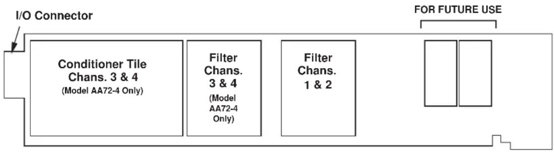
flowchart
graph LR
    A["I/O Connector"] --> B["Conditioner Tile Chans. 3 & 4 (Model AA72-4 Only)"]
    A --> C["Filter Chans. 3 & 4 (Model AA72-4 Only)"]
    A --> D["Filter Chans. 1 & 2"]
    E["FOR FUTURE USE"] --> F["Output"]
NOTE: Fig. 1 shows the stand-off circuit boards (or "tiles") that provide the analog filtering for an AA72 card's data channels.
WARNING
THE CONDITIONER TILE FOR CHANNELS 3 AND 4 OF A MODEL AA72-4 IS TO BE INSTALLED OR REMOVED ONLY BY A QUALIFIED TECHNICIAN, SINCE SUBSEQUENT REALIGNMENT OF THE AA72 CARD IS REQUIRED. FILTER TILES, HOWEVER, MAY BE INSTALLED OR REMOVED BY THE USER, IN THE FIELD. CONTACT THE DAYTRONIC SERVICE DEPARTMENT FOR COMPLETE INSTRUCTIONS.
THE FOLLOWING AA72-2 / AA72-4 VERSIONS ARE CURRENTLY AVAILABLE:
- Model AA72-2F010—Two input channels, with FIXED 10-Hz FILTERING for each
- Model AA72-2F050—Two input channels, with FIXED 50-Hz FILTERING for each
- Model AA72-2F1—Two input channels, with "F1" PROGRAMMABLE FILTERING for each
- Model AA72-2F2—Two input channels, with "F2" PROGRAMMABLE FILTERING for each
* NOTE: USE OF THE MODEL 10CJB-2 DUAL BRIDGE COMPLETION CARD WITH THE MODEL AA72 HAS NOT BEEN VERIFIED TO MEET CE STANDARDS, REGARDLESS OF WHETHER THE "CONVENTIONAL" OR CE-COMPLIANT I/O CONNECTOR IS BEING USED.
- Model AA72-4F010—Four input channels, with FIXED 10-Hz FILTERING for each
- Model AA72-4F050—Four input channels, with FIXED 50-Hz FILTERING for each
- Model AA72-4F1—Four input channels, with "F1" PROGRAMMABLE FILTERING for each
- Model AA72-4F2—Four input channels, with "F2" PROGRAMMABLE FILTERING for each
ADDITIONAL AA72-2 / AA72-4 SPECIFICATIONS
Number of Input Channels: Two for Model AA72-2; four for Model AA72-4
Transducer Types: Conventional 4-arm strain gage bridges, nominal 350 ohms (or higher); 1/4- and 1/2-bridge gage configurations can be accommodated by means of the Model 10CJB-2 Dual Bridge Completion Card described in Section 4 (or equivalent external bridge-completion circuitry supplied by the user)*
Input Ranges (Full-Scale): See Table 1; automatically selected—on an individual channel basis—when the channel is configured; for “type” codes assigned to AA72 data channels, see Appendix A of the latest Daytronic Conditioner Cards Catalog. Since channel zeroing is by digital techniques, no input balance control is provided. The allowable input range, therefore, must include any initial unbalance (which, in commercially produced strain gage transducers, is usually negligible). Other transducers may have to be externally trimmed to be used with the Model AA72, if zero unbalance exceeds 20% of full scale.
Table 1 Model AA72 Ranges
1-V Excitation 5V Excitation 10-V Excitation
| 7.5 mV/V | 1.5 mV/V | 0.75 mV/V |
| 15.0 mV/V | 3.0 mV/V | 1.50 mV/V |
| 30.0 mV/V | 6.0 mV/V | 3.00 mV/V |
Excitation (per channel): Selectable 1, 5, or 10 V-DC (i.e., ±0.5, ±2.5, or ±5 V-DC, respectively), nominal; ±40 mA, maximum, for each voltage, subject to 120 mA total current draw for all four channels**
Amplifier (per channel):
Normal-Mode Range: ±40 mV operating (±3.6 mV/V with 10-V excitation); ±8 V without instrument damage
Common-Mode Range: ±1 V operating; ±8 V without instrument damage
Common-Mode Rejection Ratio: DC and at 60 Hz: -120 dB
Input Impedance: Differential: greater than 10,000 MΩ; Common-Mode: greater than 10,000 MΩ
Offset: Initial: ±0.02 mV; vs. Temperature: ±1 μV/°C; vs. Time: ±5 μV/month
Gain Accuracy: ±0.02% of full scale
Gain Stability: vs. Temperature: ±50 ppm/°C; vs. Time: ±20 ppm/month
Filter (per channel): 3-pole modified Butterworth
"F1" Programmable Filtering (all four channels): Switch- or software-selectable to one of 16 different cutoff frequencies: 0.2; 0.4; 0.8; 1.0; 1.6; 2.0; 4.0; 5.0; 8.0; 10; 20; 25; 40; 50; 100; or 200 Hz (see Table 2)
(cont'd)
"F2" Programmable Filtering (all four channels): Switch- or software-selectable to one of 16 different cutoff frequencies: 2; 4; 8; 10; 16; 20; 40; 50; 80; 100; 200; 250; 400; 500; 1000; or 2000 Hz (see Table 3)
Fixed Filtering (all four channels): 10 or 50 Hz (see Table 4)
Table 2 "F1" Programmable Filter Characteristics for "AA" Cards
| Bandwidth Step-Response Settling Time | |||||
| Selected Response Response to 1% of to 0.1% of to 0.02% of Frequency at -3 dB at -60 dB final value final value final value (Hz) (Hz) (Hz) (msec) (msec) (msec) | |||||
| 0.2 | 0.2 | 3.9 | 3500 | 4250 | 4750 |
| 0.4 | 0.4 | 7.8 | 1750 | 2125 | 2375 |
| 0.8 | 0.8 | 16 | 875 | 1063 | 1188 |
| 1.0 1.0 | 20 | 700 850 950 | |||
| 1.6 1.6 | 31 | 438 531 594 | |||
| 2.0 2.0 | 39 | 350 425 475 | |||
| 4.0 4.0 | 78 | 175 213 238 | |||
| 5.0 5.0 | 98 | 140 170 190 | |||
| 8.0 8.0 156 | 88 106 119 | ||||
| 10.0 | 10.0 | 195 | 70 | 85 | 95 |
| 20.0 | 20.0 | 390 | 35 | 43 | 48 |
| 25.0 | 25.0 | 488 | 28 | 34 | 38 |
| 40.0 | 40.0 | 780 | 18 | 21 | 24 |
| 50.0 | 50.0 | 975 | 14 | 17 | 19 |
| 100.0 | 100.0 | 1950 | 7.0 | 8.5 | 9.5 |
| 200.0 | 200.0 | 3900 | 3.5 | 4.3 | 4.8 |
Table 3 "F2" Programmable Filter Characteristics for "AA" Cards
| Bandwidth Step-Response Settling Time | |||||
| Selected Response Response to 1% of to 0.1% of to 0.02% of Frequency at -3 dB at -60 dB final value final value final value (Hz) (Hz) (Hz) (msec) (msec) (msec) | |||||
| 2 | 2 | 40 | 375 | 430 | 480 |
| 4 | 4 | 80 | 190 | 215 | 240 |
| 8 | 8 | 160 | 90 | 110 | 120 |
| 10 | 10 | 200 | 75 | 90 | 100 |
| 16 | 16 | 320 | 45 | 55 | 60 |
| 20 | 20 | 400 | 38 | 43 | 50 |
| 40 | 20 | 800 | 18 | 22 | 25 |
| 50 | 50 | 1000 | 15 | 18 | 20 |
| 80 | 80 | 1600 | 9.0 | 11 | 12 |
| 100 | 100 | 2000 | 7.5 | 9.0 | 10 |
| 200 | 200 | 4000 | 4.0 | 4.5 | 5.0 |
| 250 | 250 | 5000 | 3.0 | 3.5 | 4.0 |
| 400 | 400 | 8000 | 2.0 | 2.2 | 2.5 |
| 500 | 500 | 10000 | 1.5 | 2.0 | 2.0 |
| 1000 | 1000 | 20000 | 0.75 | 0.9 | 1.0 |
| 2000 | 2000 | 40000 | 0.4 | 0.5 | 0.55 |
Table 4 Fixed Filter Characteristics for "AA" Cards
| Bandwidth Step-Response Settling Time | |||||
| Response Response to 1% of to 0.1% of to 0.02% of Filter at -3 dB at -60 dB final value final value final value | |||||
| Designation | (Hz) (Hz) (msec) (msec) (msec) | ||||
| “F010” | 10 | 195 | 70 | 85 | 95 |
| “F050” | 50 | 975 | 14 | 17 | 19 |
Auxiliary Outputs: Nominal ±5 V-DC signals available as input to an Analog Signal Processor Card; individually jumper-selectable to represent either the filtered or prefiltered (5-kHz bandwidth) reading of the channel
Power-Supply Slot Allotment: Maximum consumption of supply current from the Conditioner Card Slot is 200 mA (the actual consumption for any given AA72 channel will depend on its transducer bridge resistance and excitation level)
2 TRANSDUCER CONNECTIONS
IMPORTANT
The type of I/O CONNECTOR to be used with the Model AA72 will depend on whether or not you wish your SPS6000 system to comply with CE standards.
If CE compliance is NOT required, you may use the “conventional” connector that comes with the AA72 card (shown in Fig. 2). If CE compliance is required, you MUST use the Model CAA72-CE Conditioner Connector (shown in Fig. 3), which is ordered separately from the AA72 card. Both “conventional” and “CE-compliant” connectors are fully described in Manual Section 2.b.3.
ALSO NOTE: CE COMPLIANCE FURTHER REQUIRES THE CABLE SHIELDING SHOWN IN FIG. 5(a) OR 5(b). For more information on the "CONNECTION OF CABLE SHIELD," see Manual Section 2.b.3.
The connections shown in Fig. 5 represent EITHER “CONVENTIONAL” AA72 CABLING (using the “conventional AA” connector that comes with the AA72 card) OR CE-COM-PLIANT CABLING (using the Model CAA72-CE).
4-wire connections to a full-bridge strain gage transducer are given in Fig. 5(a). This cabling is to be used when the cable is under 20 feet in length. In this case, the +SENSE and -SENSE lines are tied to the corresponding EXCITATION lines (and also the CALIBRATION SENSE line to the +SIGNAL line) at the CONDITIONER CONNECTOR. It is recommended that the resistance of the conductors not exceed 0.0001 of the bridge resistance.
8-wire connections to a full-bridge strain gage transducer are given in Fig. 5(b). This cabling is to be used when the cable is 20 feet or longer, or when fine wire is used. In this case, the +SENSE and -SENSE lines are tied to the corresponding EXCITATION lines (and also the CALIBRATION SENSE line to the +SIGNAL line) at the transducer. Note also the extra wire connected to the -SIGNAL line at the transducer, but left unconnected at the AA72. This wire is to be paired with the CAL SENSE line to establish proper shielding and to avoid asymmetrical dynamic loading.
IMPORTANT: The ±EXCITATION, ±SENSE, and ±SIGNAL terminals for an UNUSED STRAIN GAGE INPUT CHANNEL should be jumpered as shown in Fig. 4, below (which applies to either “conventional” or CE-compliant cabling). If an input is left open, high-frequency oscillation can result, which can in turn produce significant interchannel crosstalk, and possibly inaccurate data readings.
ALSO NOTE: Logic connections for remote control of shunt calibration (using the CONDITIONER CONNECTOR'S "NOT ±CALIBRATE" terminals) are discussed in Section 3.d and shown in Fig 7. For connection of an optional Model 10CJB-2 Dual Bridge Completion Card to the AA72—without verified compliance to CE standards—see Section 4.b.
Shunt Resistors:

Fig. 2 Model AA72
"CONVENTIONAL"
Connector Assembly Board

Fig. 4 Jumpering of an Unused AA72 Strain Gage Input ("CONVENTIONAL" or CE-COMPLIANT Cabling)
Model CAA72-CE CONDITIONER CONNECTOR

Fig. 5 Model AA72 Transducer Cabling ("CONVENTIONAL" or CE-COMPLIANT

flowchart
graph TD
    A["AA72-2: Channel 1 or 2"] --> B["+EXCITATION"]
    C["AA72-4: Channel 1, 2, 3, or 4"] --> D["+SIGNAL-SIGNAL"]
    D --> E["-EXCITATION"]
    B --> F["See Fig. 7"]
    D --> F
    F --> G["SHIELD (SHLD)"]
    F --> H["+EXCITATION (+EX)"]
    F --> I["+SENSE (+SEN)"]
    F --> J["+SIGNAL (+SIG)"]
    F --> K["-SIGNAL (-SIG)"]
    F --> L["CAL SENSE (CAL SEN)"]
    F --> M["-SENSE (-SEN)"]
    F --> N["-EXCITATION (-EX)"]
    F --> O["+CAL COMMAND (+CAL)"]
    F --> P["-CAL COMMAND (-CAL)"]
    F --> Q["POWER COMMON (PWR COM)"]
    style A fill:#f9f,stroke:#333
    style C fill:#f9f,stroke:#333
    style B fill:#ccf,stroke:#333
    style D fill:#ccf,stroke:#333
    style F fill:#cfc,stroke:#333
Fig. 5(a) 4-Wire Strain Gage Cabling (under 20 ft. in length)

flowchart
graph TD
    A["AA72-2: Channel 1 or 2: AA72-4: Channel 1, 2, 3, or 4"] --> B["+SENSE"]
    B --> C["+EXCITATION"]
    C --> D["+SIGNAL-SIGNAL"]
    D --> E["CAL SENSE"]
    E --> F["-EXCITATION"]
    F --> G["-SENSE"]
    G --> H["Extra Wire (paired with "CAL SENSE," UNCONNECTED at Conditioner Connector)"]
    H --> I[""Conventional" AA72 OR Model CAA72-CE CONDITIONER CONNECTOR (CAA72-CE REQUIRED FOR CE COMPLIANCE)"]
    I --> J["SHIELD (SHLD)"]
    I --> K["+EXCITATION (+EX)"]
    I --> L["+SENSE (+SEN)"]
    I --> M["+SIGNAL (+SIG)"]
    I --> N["-SIGNAL (-SIG)"]
    I --> O["CAL SENSE (CAL SEN)"]
    I --> P["-SENSE (-SEN)"]
    I --> Q["-EXCITATION (-EX)"]
    I --> R["+CAL COMMAND (+CAL)"]
    I --> S["-CAL COMMAND (-CAL)"]
    I --> T["POWER COMMON (PWR COM)"]
    style A fill:#f9f,stroke:#333
    style B fill:#ccf,stroke:#333
    style C fill:#cfc,stroke:#333
    style D fill:#fcc,stroke:#333
    style E fill:#cff,stroke:#333
    style F fill:#ffc,stroke:#333
    style G fill:#cfc,stroke:#333
    style H fill:#fcc,stroke:#333
    style I fill:#ffc,stroke:#333
    style J fill:#cfc,stroke:#333
    style K fill:#cfc,stroke:#333
    style L fill:#cfc,stroke:#333
    style M fill:#cfc,stroke:#333
    style N fill:#cfc,stroke:#333
    style O fill:#cfc,stroke:#333
    style P fill:#cfc,stroke:#333
    style Q fill:#cfc,stroke:#333
    style R fill:#cfc,stroke:#333
    style S fill:#cfc,stroke:#333
    style T fill:#cfc,stroke:#333
3
SETUP AND/OR OPERATING CONSIDERATIONS
3.a SELECTION OF EXCITATION LEVELS
To set the DC excitation for each AA72 channel, you should
- Remove the AA72 card from its mainframe slot. For "Card Insertion and Removal," see Manual Section 2.b.1.
- Refer to Fig. 6 and locate the EXCITATION PROGRAMMING JUMPER PINS. For the four-channel Model AA72-4, these pins are located between the main card and the Conditioner Tile for Channels 3 and 4, but are nonetheless easily accessi-
Fig. 6 Model AA72 Programming Jumper Pins and Filter Selection Switches


POSTFILTER (FILTERED) OUTPUT

PREFILTER (UNFILTERED) OUTPUT
ble from the top of the card. One "minijumper" is provided for each channel, for interconnecting adjacent jumper pins.
- Position the jumper for each channel as shown in Fig. 6 to interconnect the pair of pins corresponding to the desired excitation voltage for that channel (1, 5, or 10 V).* You will need to use a small pair of needle-nosed pliers to move the jumper.
- Reinsert the AA72 card in its mainframe slot.
NOTE: As explained in Section 3.d, the Input Configuration window provided for an AA72 data channel by the Configurator Software contains a field for the entry of Excitation Voltage. The value you enter in this field must match the excitation to which the channel has been set via its programming jumper on the AA72 card. You cannot "select" a desired excitation voltage for an AA72 channel via the Configurator Software; you are simply informing the system of the existing hardware setting for that channel.
3.b SELECTION OF ANALOG FILTERING
NOTE: If your AA72 card is equipped with FIXED ANALOG FILTERING, you may ignore this manual section.
Via Hardware Switches
For an AA72 card with PROGRAMMABLE ANALOG FILTERING and operating in an SPS6000 system, you will NOT normally use the card's hardware filter-setting switches
to set the respective cutoff frequencies of its channels' individual analog filters. You may do so, however, using the following procedure, if you do not want to be able to change the filters at a later time via the Configurator Software or the SPS6000 unit's front-panel FILTER Button. THE SWITCH SETTING FOR A GIVEN CHANNEL'S ANALOG FILTER WILL ALWAYS OVERRIDE ANY SETTING MADE VIA THE CONFIGURATOR SOFTWARE OR THE FRONT-PANEL FILTER BUTTON. For this reason, it is necessary to set a channel's FILTER SWITCH to "F" (as explained in the following section) in order to enable the software or Filter button to modify that channel's filter.
- Remove the AA72 card from its slot (see Section 3.a, Step 1, above).
- Refer to Fig. 6 and locate the 16-position FILTER SELECTION SWITCHES located between the main card and the Filter Tile(s).
- Referring to Table 5, below, set each channel's switch for the desired frequency. You will need to use a small screwdriver (or equivalent tool) to set the switch to the appropriate number/letter.
- Reinsert the AA72 card.
Table 5 Model AA72 Filter Switch Settings
| Cutoff Frequency“F1” Filter “F2” Filter Switch Setting | ||
| 0.2 Hz 2 Hz 7 | ||
| 0.4 Hz 4 Hz 6 | ||
| 0.8 Hz 8 Hz 5 | ||
| 1.0 Hz 10 Hz 3 | ||
| 1.6 Hz 16 Hz 4 | ||
| 2.0 Hz 20 Hz 2 | ||
| 4.0 Hz 40 Hz 1 | ||
| 5.0 Hz 50 Hz F | ||
| 8.0 Hz 80 Hz 0 | ||
| 10 Hz 100 Hz E | ||
| 20 Hz 200 Hz D | ||
| 25 Hz 250 Hz B | ||
| 40 Hz 400 Hz C | ||
| 50 Hz 500 Hz A | ||
| 100 Hz | 1000 Hz | 9 |
| 200 Hz | 2000 Hz | 8 |
VIA CONFIGURATOR SOFTWARE OR "FILTER" BUTTON
For an AA72 with PROGRAMMABLE ANALOG FILTERING and operating in an SPS6000 system, you will normally set an individual corner frequency for the analog filter of each active input channel via the SPS6000 Configurator Software. Thus, in the process of configuring an AA72 input channel using its individual Input Configuration window, you will select the desired filter cutoff frequency from the popup list that appears when you click on the arrow to the right of the Filters field.*
NOTE: The Filters field's popup list presently contains the 16 frequencies for "F1" filtering (ONLY). IF YOUR AA72 IS EQUIPPED WITH "F2" PROGRAMMABLE FILTERING, YOU SHOULD MULTIPLY EACH LISTED FREQUENCY BY "10" IN ORDER TO MAKE THE PROPER SELECTION.
After setting an AA72 channels' initial filter value—to be downloaded to the SPS6000 unit along with the rest of the configuration—you may subsequently change that value on a purely "run-time" basis, using the unit's front-panel Filter button, or the Filter button in the Configurator Software's On-Line Calibration window.* Manual Section 3.d gives complete instructions for "On-Line Selection of Analog Filtering."
IMPORTANT: TO ENABLE THE SPS6000 CONFIGURATOR SOFTWARE OR FILTER BUTTON TO SET THE ANALOG FILTER OF A GIVEN AA72 CHANNEL, THE FILTER SELECTION SWITCH FOR THAT CHANNEL MUST FIRST BE SET TO "F."
Therefore, the following steps should be taken before using the Configurator Software or Filter button for the first time to enter or modify an active AA72 channel's analog filter setting:
- Remove the AA72 card from its slot (see Section 3.a, Step 1, above).
- Refer to Fig. 6 and make sure that the FILTER SELECTION SWITCH for each active channel is set to "F." You will need to use a small screwdriver (or equivalent tool) to reset the switch, if necessary.
- Reinsert the AA72 card in its mainframe slot.
3.c SELECTION OF ANALOG OUTPUT MODES
As mentioned in Section 1, each AA72 channel's ±5-V ANALOG OUTPUT can be set to represent either the filtered or prefiltered reading of that channel. To set the output mode for each of your AA72's active input channels,** you should
- Remove the AA72 card from its slot (see Section 3.a, Step 1, above).
- Refer to Fig. 6 and locate the OUTPUT MODE PROGRAMMING JUMPER PINS beneath the AA72's Filter Tile(s). One "minijumper" is provided for each channel's set of three jumper pins.
-
Position the jumper for each channel as shown in Fig. 6 to interconnect the pair of pins that corresponds to the desired output mode for that channel. You will need to use a small pair of needle-nosed pliers to move the jumper.
-
Reinsert the AA72 card in its mainframe slot.
3.d CONFIGURATION AND CALIBRATION
For initial configuration of ANALOG INPUT CHANNELS dedicated to a specific Model AA72 card when used in SPS6000, see Manual Sections 3.a and 3.b.
In the SPS6000 System, you can perform any of the three following calibration methods with the Model AA72, unless it is being used with a Model 10CJB-2 Dual Bridge Completion Card (in which case a special calibration procedure is required, as explained in Section 4.c).
* As with Filters field in the Input Configuration window, the Filter button presently invokes only the "F1" list of cutoff frequencies. IF YOUR AA72 IS EQUIPPED WITH "F2" PROGRAMMABLE FILTERING, YOU SHOULD MULTIPLY EACH LISTED FREQUENCY BY "10" IN ORDER TO MAKE THE PROPER SELECTION.
** The output mode setting for an UNUSED channel is immaterial, and will not affect operation of the AA72.
CALCULATED CALIBRATION
In an SPS6000 system, a nominally accurate CALCULATED CALIBRATION should be initially applied to every Model AA72 channel, even if you intend to perform additional "two-point" or "shunt" calibration (see Manual Sections 3.b and 3.e.5 for a general discussion of this calibration technique). To do so, you will enter an appropriate value for each of the following parameters in the channel's Input Configuration window:
- FILTERS: Select from the popup list the desired cutoff frequency for the channel's analog filter (as noted previously, only the "F1" filter settings are listed; for the corresponding "F2" settings (if required), multiply by 10—see Tables 2 and 3, respectively).
- EXCITATION VOLTAGE: Select from the popup list the excitation level to which this channel is presently set via a programming jumper on the AA72 card (Section 3.b, above). NOTE: You cannot "set" the channel's excitation voltage through the software; you are simply informing the system of the existing hardware setting.
- DESC: Enter here the desired engineering units in which the channel's final measurement value is to be expressed, as an alphanumeric string of up to four characters.
NOTE: The four following numbers will be automatically set to the highest precision that is presently displayable by the system, based on the currently entered full-scale transducer range and the system's full scale of "32767" for display A/D conversion.
Also note that the Configurator Software will display an appropriate error message if you try to enter a "Transducer" or "Output" value that is incompatible with one or more existing calibration settings. For example, it will not let you specify too much (or too little) input signal for the presently specified transducer full-scale range—or an output offset that lies outside the range allowed by previously entered calibration values.
• TRANSDUCER INFORMATION:
- FULL SCALE RANGE: Enter here the full-scale rating of the AA72 channel's source transducer, expressed in the engineering units entered in the DESC field, as specified by the transducer manufacturer. NOTE: If you attempt to enter a value of full-scale range that yields either not enough or too much input signal for the card type, the software will ask you whether you want the transducer full-scale range and the full-scale output to be set equal (you may answer Ok or Cancel).
- FULL SCALE OUTPUT (ELECTRICAL UNITS): Enter here the full-scale output of the AA72 channel's source transducer, expressed in mV/V, as specified by the transducer manufacturer.
• OUTPUT INFORMATION:
- FULL SCALE OUTPUT ([specified units]): Enter here the desired full-scale measurement (to be represented by a full-scale analog output of 10 V-DC), expressed in the engineering units entered in the DESC field.
- OFFSET ([specified units]): Enter here the desired zero offset to be applied to the AA72 channel's measurement reading, expressed in the engineering units entered in the DESC field.
Remember that CALCULATED CALIBRATION will not go into effect until the configuration that contains the user-entered calibration values is downloaded to the SPS6000 system via the procedure given in Manual Section 3.c.4.
TWO-POINT (DEADWEIGHT) CALIBRATION
If an AA72 channel's initial software-calculated calibration does not yield sufficient accuracy—or if the full-scale “mV/V” rating of the strain gage transducer is unknown—additional calibration can be performed “on-line,” using the Configurator Software’s On-Line Calibration window or the system’s front-panel display/keypad. Manual Section 3.e.6 gives general instructions for this conventional “zero and span” calibration technique.
If you want to permanently save the scaling and offset values established during deadweight calibration, be sure to apply a SAVE ONLINE CHANGES command as soon as calibration is complete (see Manual Section 3.e.4).
NOTE: Calibrated Full Scale Output (Electrical Units) and Calibrated Offset values are displayed in an AA72 channel's Input Configuration window. Initially, these "calibrated" values will be the same as the last user-entered Full Scale Output and Offset values to have been downloaded to the SPS6000. However, as soon as a "zero" calibration point is entered during on-line calibration of this channel—by either the "TWO-POINT (DEADWEIGHT)" or "SIMULATED (SHUNT)" method—the "calibrated" zero offset of the output signal is automatically determined and applied by the system. As soon as a "span" calibration point is entered during on-line calibration, the "calibrated" electrical output of the source transducer is automatically determined and applied, in order to achieve the desired scaling. The displayed Calibrated Full Scale Output then represents the actual value of full-scale transducer output (in electrical units) currently in effect within the SPS6000 system, while the displayed Calibrated Offset represents the actual output offset currently in effect, in the specified engineering units. For a properly calibrated channel, there should be little difference between the actual "calibrated" output/offset values and the respective stored values—i.e., the last user-entered output/offset values to have been downloaded to the SPS6000. Ideally, the two values should be equal.
SIMULATED (SHUNT) CALIBRATION
Suitable for all AA72 excitation levels, this is a convenient “shunt resistor” method, especially when overall deadweight calibration is impractical.* Here the second (“span”) input is not produced by loading the source transducer, but by “simulating” a particular up-scale value of mechanical input. This known EQUIVALENT INPUT then serves to determine the SCALING FACTOR for the channel.
Like deadweight calibration, shunt calibration can be performed "on-line," using the Configurator Software's On-Line Calibration window or the system's front-panel display/keypad. You should refer to Manual Section 3.e.7 for general theory and instructions on this standard "shunt cal" technique.
If you want to permanently save the scaling and offset values established during deadweight calibration, be sure to apply a SAVE ONLINE CHANGES command as soon as calibration is complete (see Manual Section 3.e.4).
The AA72 is equipped with a 100-kΩ, 0.1% calibration resistor for each active channel. These resistors are located on turret terminals on the Connector Assembly Board (see Fig. 2 or 3). You may, if you wish, replace each channel's installed 100K shunt resistor with a resistor of another value (strain-gage transducer manufacturers often supply such resistors with their instruments).
Fig. 7 Logic Inputs for AA72 Remote Shunt Calibration ("CONVENTIONAL" or CE-COMPLIANT Cabling)


flowchart
graph TD
    A["TTL TTL"] --> B["+5 V +5 V"]
    B --> C["SHIELD (SHLD)"]
    B --> D["+EXCITATION (+EX)"]
    B --> E["+SENSE (+SEN)"]
    B --> F["+SIGNAL (+SIG)"]
    B --> G["-SIGNAL (-SIG)"]
    B --> H["CAL SENSE (CAL SEN)"]
    B --> I["-SENSE (-SEN)"]
    B --> J["-EXCITATION (-EX)"]
    B --> K["+CAL COMMAND (+CAL)"]
    B --> L["-CAL COMMAND (-CAL)"]
    B --> M["POWER COMMON (PWR COM)"]
Manual Section 3.e.7 explains how an AA72 channel's shunt resistor may be easily switched in and out by means of the +SHUNT or -SHUNT button on the SPS6000 unit's front-panel display/keypad or in the Configurator Software's On-Line Calibration window. Note, however, that per-channel shunt calibration can be "remotely" controlled, if desired, as an alternative to using the system keypad or software. This remote calibration control is accomplished by means of logic-level inputs to the AA72 card. The relevant connections are given in Fig. 7, above (for either "CONVENTIONAL" cabling via the standard AA72 Conditioner Connector or CE-COMPLIANT cabling via the Model CAA72-CE). NOTE THAT CE COMPLIANCE REQUIRES THE CABLE SHIELDING SHOWN IN FIG. 7.
Fig. 7(a) shows how the “CALIBRATE POSITIVE” and “CALIBRATE NEGATIVE” commands can be independently applied to any active AA72 channel, without the need of an external logic reference supply.
Closing the switch in Fig. 7(a) to contact point "A" will produce a Logic 0 level at the "NOT +CAL COMMAND" terminal. Since this is a negative-true logic line, the Logic 0 input will activate the "+CALIBRATE" condition of the channel. That is, it will switch in the channel's shunt resistor for a positive up-scale reading. Opening the switch to disconnect the "NOT +CAL COMMAND" terminal from POWER COMMON will then return the channel to the "NO +CALIBRATE" condition.
Similarly, closing the switch to contact point "B" will produce a Logic 0 level at the "NOT -CAL COMMAND" terminal, thereby switching in the channel's shunt resistor for a negative up-scale reading. Opening the switch to disconnect the "NOT -CAL COMMAND" terminal from POWER COMMON will then return the channel to the "NO -CAL IBRATE" condition.
You may also use active TTL logic, as illustrated in Fig. 7(b), to produce the “+CALIBRATE” or “-CALIBRATE” condition for any AA72 channel.
4 OPTIONAL BRIDGE COMPLETION: MODEL 10CJB-2 DUAL BRIDGE COMPLETION CARD
4.a PURPOSE
The optional Model 10CJB-2 Dual Bridge Completion Card lets you connect each of your Model AA72's inputs to a 2-wire 1/4-bridge, 3-wire 1/4-bridge, 1/2-bridge, or full-bridge strain gage configuration.* Each 1/4-bridge configuration may use either 120 or 350 ohms nominal gage resistance. The function of the Model 10CJB-2 is to "complete" the connected bridge—that is, to allow it to be "seen" by the Model AA72 as a full (4-arm) Wheatstone bridge.
Fig. 8 Model 10CJB-2 Transducer Cabling

* Two 10CJB-2 units may be used, if desired, with a Model AA72-4.
For calibration of AA72 channels originating from the Model 10CJB-2, see Section 4.c, below.
NOTE: USE OF THE MODEL 10CJB-2 DUAL BRIDGE COMPLETION CARD WITH THE MODEL AA72 HAS NOT BEEN VERIFIED TO MEET CE STANDARDS, REGARDLESS OF WHETHER THE "CONVENTIONAL" OR CE-COMPLIANT I/O CONNECTOR IS BEING USED.
4.b 10CJB-2 TRANSDUCER CONNECTIONS
Remove the top plate of the Model 10CJB-2 box (4 screws in corners). Inside the box are two sets of labelled screw terminals, one for each of the AA72's input channels ("A" and "B"). As shown in the following figures, you will connect your gage wires directly to these terminals, and, if necessary, interconnect certain terminal pairs by means of jumper wires. Gage leads should enter the 10CJB-2 through the cutout on the right-hand side of the box.
NOTE: A SPECIAL DAYTRONIC CABLE MUST BE USED TO CONNECT THE 10CJB-2 TO THE AA72'S REAR I/O CONNECTOR. Contact the Daytronic Service Department for full details.
Fig. 8(a) shows connections between the 10CJB-2 and a 2-wire 1/4-bridge gage configuration (represented by the single gage resistor). Here, you must install a jumper wire between the -SIG and 1/2 BR terminals, and between the +SIG terminal and either the 120 terminal or the 350 terminal, depending on the nominal gage resistance.
Fig. 8(b) shows connections between the 10CJB-2 and a 3-wire 1/4-bridge gage configuration (again represented by the single gage resistor). Here again, the -SIG and 1/2 BR terminals must be tied. The gage's third (self-compensating) lead is connected either to the 120 terminal or to the 350 terminal, depending on the nominal gage resistance.
Fig. 8(c) shows connections between the 10CJB-2 and a 1/2-bridge gage configuration (represented by the two connected gage resistors). Here again, the -SIG and 1/2 BR terminals must be tied.
Fig. 8(d) shows connections between the 10CJB-2 and a full-bridge gage configuration (represented by the four connected gage resistors).
4.c CALIBRATION
CALCULATED CALIBRATION
For AA72 channels receiving strain-gage inputs from a Model 10CJB-2 Bridge Completion Card, you may use the same basic procedure as described in Section 3.d, above. Note however that, in this case,
- for FULL-SCALE OUTPUT (ELECTRICAL UNITS) under TRANSDUCER INFORMATION, you should enter one of the following full-scale "mV/V" values, whichever is appropriate for the strain-gage configuration: 0.75, 1.50, 3.00.
- for the FULL-SCALE RANGE under TRANSDUCER INFORMATION, you should enter the full-scale microstrain range that corresponds to the selected FULL-SCALE OUTPUT (ELECTRICAL UNITS) rating, as given in the following table.
Table 6 Strain Gage Microstrain Ranges (AA72)
| Full-Scale Output (mV/V) | Full-Scale Microstrain Range |
| 0.75 | u = 3000 / (N · G) |
| 1.50 | u = 6000 / (N · G) |
| 3.00 | u = 12000 / (N · G) |
Here, “N” is the number of active strain-gage arms in the gage configuration. Thus, for a 1/4-bridge gage, N = 1; for a half-bridge gage, N = 2; and for a full-bridge gage, N = 4. “G” is the gage factor of the strain gage, and is normally provided by the manufacturer.
Remember that CALCULATED CALIBRATION will not go into effect until the configuration that contains the user-entered calibration values is downloaded to the SPS6000 system via the procedure given in Manual Section 3.c.4.
Two-Point (Deadweight) Calibration
See Manual Section 3.e.6 for the general procedure. Your first calibration point, entered via the Zero button, should be zero. Your second calibration point, entered via the Span button, should be expressed in microstrain (microinches/inch).
SIMULATED (SHUNT) CALIBRATION
See Manual Section 3.e.7 for the general procedure. Your EQUIVALENT INPUT value, which is entered via the +Shunt or -Shunt button (following zeroing of the channel via the Zero button), should be expressed in microstrain (microinches/inch).
Coarse Zero Offset
In the event that, during “Two-Point” or “Simulated” calibration of the 10CJB-2 channel, you are unable to set the desired span via the Span button, you can apply a positive or negative zero offset of approximately 1 mV/V for balance correction, as follows:
- Remove the top plate of the 10CJB-2 box and locate the three programming jumper pads for the channel in question. Labelled "A" for Channel 1 and "B" for Channel 2, the pads are near the left edge of the 10CJB-2 circuit board.
- Place a solder drop between the center pad and either the "+" or "-" pad, depending on the desired offset polarity.
- Re-enter your Zero and Span values (with or without calibration "shunt").
5 D IAGNOSTIC WIRE-WRAP PINS
As a special diagnostic and service tool, the five pins shown in Fig. 9 are directly accessible from the front of an installed AA72 card. These pins allow voltmeter or oscilloscope observation of data-channel output signals. THEIR USE IS INTENDED PRIMARILY FOR TRAINED SERVICE TECHNICIANS. With regard to the on-board diagnostic pins, please note the following:
- PROPER ESD PRACTICE SHOULD BE OBSERVED WHEN MAKING CONTACT WITH AN AA72 BOARD INSTALLED IN A "LIVE" DAYTRONIC SYSTEM MAINFRAME. ALWAYS GROUND YOURSELF TO THE MAINFRAME CHASSIS BEFORE TOUCHING THE BOARD.
- THE ANALOG SIGNAL PRESENT AT EACH ACTIVE "CHANNEL" PIN REPRESENTS EIGHT TENTHS (0.8) OF THAT CHANNEL'S NOMINAL CALL-BUS VOLTAGE. For a channel delivering a standard full-scale (+5-V) output, the corresponding diagnostic pin will therefore register +4 V.
- THE ANALOG SIGNAL PRESENT AT EACH ACTIVE "CHANNEL" PIN REPRESENTS THE FILTERED CHANNEL OUTPUT, AND IS NOT AFFECTED BY THE ANALOG OUTPUT MODE CURRENTLY SELECTED FOR THAT CHANNEL (see Section 3.c).
- THE "SLOT CALL" PIN DELIVERS A LOGIC SIGNAL THAT MAY BE USED TO SYNCHRONIZE AN OSCILLOSCOPE FOR TIMING ANALYSIS OF THE AA72 CARD.
- THE "CHANNEL 3" AND "CHANNEL 4" PINS ARE ONLY ACTIVE FOR AN AA72-4 CARD.
Fig. 9 Diagnostic Wire-Wrap Pins

APPENDIX B
SPS6000 FUNCTION MODULES
CONCERNING FUNCTION MODULE LOGIC I/O SIGNALS
As you study the Function Module Configuration diagrams given in this appendix, remember that the function associated with the "true" (or "asserted") state of a given function module logic input or output is generally implied by the name of that input or output. For example, when an input named "Hold" is "true," the present input signal value will be "held"; when an output named "Have Peak" is "true," a peak value of the input signal has been captured; when an input named "Enable Y1" is "true," the output "Y1" is enabled.
The “true” logic state of a given input or output is normally represented by “Logic 1.” This is called “positive true” logic, since for the SPS6000 system, “Logic 1” is defined as a positive voltage from 5 to 20 V. However, as the Function Module Configuration windows indicate, you may specify “inverted” (or “negative true”) logic for some logic functions, when required by the application.
In the inverted state, a function module logic input or output will be at "Logic 0" (0 V) when "true"—or, equivalently, at "Logic 1" when "false." For example, in its "normal" state the HAVE PEAK output of the Model SPS9702 Peak and Track/Hold Module is at a "Logic 1" level when the statement "A peak has been captured" is true. In its "inverted" state, however, the "true" condition of the Have Peak output is represented by "Logic 0." In this case, Have Peak will be at "Logic 1" only when the statement "A peak has been captured" is false.
ALSO NOTE: Figs. B.1, B.2, B.8, and B.10-B.12 show the default states which the respective Function Module Configuration window's "Invert" fields will assume when that window is first invoked. In most cases, at least one logic function will be initially "inverted." BE SURE THAT THE "INVERSION" STATUS OF ALL LOGIC FUNCTIONS IS APPROPRIATE FOR YOUR APPLICATION BEFORE DOWNLOADING THE CONFIGURATION TO THE SPS6000 SYSTEM.
B.1 MODEL SPS6701 SUM/DIFFERENCE MODULE
The Model SPS6701 Sum/Difference Module is used to calculate the algebraic sum of two or more independent analog signals that have equivalent scaling. As shown in Fig. B.1 (the SPS6701's Function Module Configuration window), the module has 6 analog inputs. The first four inputs are additive; the last two are subtractive. Of course, "adding" a subtractive signal to another signal amounts to calculating the difference between them.
The Sum/Difference Module has two analog outputs. The Sum Output continuously represents the algebraic summation of all active inputs, additive and subtractive. If, for example, Input Nos. 1, 2, and 5 have been "activated" by assigning each of them a unique tag name, and the value of Input No. 1 at any moment is "x," that of Input No. 2 is "y," and that of Input No. 5 is "z," then the value of the Sum Output will continuously equal
$$ \mathbf {x} + \mathbf {y} - \mathbf {z} $$
The - Sum Output is simply the present value of the Sum Output with opposite polarity.

Fig. B.1 Model SPS6701 Configuration Window
PLEASE NOTE: ALL SPS6701 INPUTS MUST BE SCALED USING THE SAME ENGINEERING UNITS SPECIFICATION AND THE SAME "FULL-SCALE OUTPUT" SETTING IN THEIR RESPECTIVE INPUT CONFIGURATION WINDOWS (see Section 3.b, Steps 35 and 36).
ALSO: SPS6701 INPUTS SHOULD BE SCALED SUCH THAT THE MAXIMUM EXPECTED SUMMATION DOES NOT EXCEED THE SYSTEM OVERRANGE VALUE OF 10.000 V.
Typical applications of the Sum/Difference Module include
- measurement of material thickness or diameter by adding the signals produced by two opposing LVDT sensors
- measurement of material taper by calculating the difference between the signals produced by two parallel LVDT sensors
- measurement of total indicated runout (TIR) of a rotating part by calculating the difference between the maximum (+ peak) and minimum (- peak) of a single LVDT signal, as captured by a Peak and Track/Hold Module (see below)
- obtaining an error signal in a closed-loop servo system (the difference between a command signal and a feedback signal)
B.2
MODEL SPS6702 PEAK AND TRACK/HOLD MODULE
The extremely versatile Model SPS6702 Peak and Track/Hold Module accepts a single analog input signal and produces two analog outputs (see Fig. B.2). As explained below, the value of the analog signal labelled "Output" is continuously determined by the existing value of the module's single analog Input signal, by the status of the module's four logic control inputs and, in some cases, by certain setup entries made by the user in the SPS6702 Configuration window. The value of the signal labelled "Input - Output" is simply the algebraic difference between the present value of the Input signal and the present value of the Output signal.
Note that the "default" state of all four SPS6702 logic inputs—that is, the state each input will assume when it is uncommitted—is "false." Optional "inversion" of each input (with the exception of Dis(able) Acquire) can be specified in the SPS6702 Configuration window. Optional "inversion" of the Have Peak logic output can also be specified.*

Fig. B.2 Model SPS6702 Configuration Window
The easiest way to understand the use of the SPS6702's control inputs is to look at the three main ways in which this module can operate:*
B.2.a "TRACK AND HOLD" OPERATION
When the Track input is "true" and the Hold input is "false," the value of the Output signal will be continuously identical to that of the Input signal. As the Input value varies, no signal peaks will be captured and no value will be "held."
Fig. B.3 shows how the Output "tracks" the Input as long as Track is "true" and Hold is "false" (from time t_0 to t_1 and following time t_2 ). When the Hold input goes "true" at time t_1 , however, the analog Output value "freezes" at the value that existed at that time. At time t_2 , the Hold is released (goes "false"), and the Output begins once again to track the Input.
NOTE: Since the SPS6702 uses purely analog capture and storage techniques, each and every "held" signal value will decay at the user-specified "leak rate" (see below), or, if a leak rate of zero is specified, at less than 0.1% of full scale per second. For indefinite digital hold of an input-signal value without decay, the Model SPS6703 Auto Zero Module can be used (see Section B.3).
B.2.b "PEAK CAPTURE AND HOLD" OPERATION
When both the Track input and the Hold input are "false," the value of the Output signal will represent the greatest maximum or minimum value experienced by the Input signal since peak capture operation last began. Any captured peak can be "held" by subsequently causing the Hold input to go "true."
If the user has selected the Positive Peak Mode for the SPS6702 in the SPS6702 Configuration window, the Output signal will represent the most positive (or least negative) Input value received since peak capture operation last began. If Negative Peak Mode
Fig. B.3 SPS6702 Track and Hold Operation

line
| Time Point | Input | Output | | ---------- | ----- | ------ | | t0 | Low | Low | | t1 | Medium| Medium | | t2 | High | High |Fig. B.4 SPS6702 Peak Capture and Hold Operation (Successively Higher-Valued Maxima)

line
| Time Point | Value | | ---------- | ----- | | t0 | INPUT | | t1 | OUTPUT (+ PEAK) | | t2 | P1 | | t3 | P2 | | t4 | P2 | | t5 | TRUE | | t5 | FALSE | | t5 | TRUE | | t5 | FALSE |has been selected, the Output signal will represent the least positive (or most negative) Input value received since peak capture operation last began.
Fig. B.4 shows the capture of successively higher-valued signal maxima when the SPS6702 is set for “+ Peak” operation. Until time t_1 , the Output continuously tracks the Input. After time t_1 , it continuously reports the highest Input value perceived since Track was released. From time t_1 to time t_2 , the Input signal is continuously rising, and so the Output appears to be continuing to track it. At time t_2 , however, the Input signal reaches its first true maximum since time t_1 . The Output “captures” this positive peak ( P_1 ), holding it as a constant value until time t_3 , when a yet higher Input value is detected, and the Output begins once more to track the Input upwards to a yet higher peak ( P_2 ).
Fig. B.4 also shows the application of Hold during “+ Peak” operation. When the Hold input goes “true” at time t_5 , the “frozen” analog Output no longer responds to a higher-valued Input.
Fig. B.5 shows the capture of successively lower-valued signal minima when the module is set for “- Peak” operation. In this case, the Track and Hold inputs do not change from their initial “false” state. The initial Input minimum (time t_0 ) is held until the Input signal reaches a lower value at time t_1 . At this time the Output appears to begin to track the Input down to the first true negative peak ( P_1 ). This peak value will be captured at time t_2 and held until a still lower Input value is detected at time t_3 whereupon the Output will track down to the second, lower peak ( P_2 ), etc.
The module's Have Peak logic output will be "true" when Track is "false" and when the Output signal differs from the Input signal by more than a preset threshold amount. A "true" Have Peak output thus indicates that a valid positive or negative peak has been captured. The Have Peak Threshold value is directly entered by the user in the SPS6702 Configuration window in the engineering units assigned to the Output. Note that an SPS6702's Have Peak output can serve as the "Level Trigger" logic input for an Auto Zero Module, thus enabling a captured peak value to be held by that module for an indefinite period of time without decay (see Section B.3).
Fig. B.5 SPS6702 Peak Capture Operation (Successively Lower-Valued Minima)

line
| Time Point | Logic Inputs | | ---------- | ------------ | | t0 | OUTPUT (- PEAK) | | t1 | P1 | | t2 | P2 | | t3 | P2 | | t4 | P2 |Fig. B.6 SPS6702 Capture and Hold of Successively Lower-Valued Maxima Using Peak "Reset"

line
| Time Point | Input | Output (+ Peak) | | ---------- | ----- | --------------- | | t0 | Low | Low | | t1 | Peak | High | | t2 | Low | Low | | t3 | Peak | High | | t4 | Low | Low |PLEASE NOTE: The polarity of the user-entered threshold value should be the opposite of the selected Peak Mode. If, for example, Positive Peak Mode has been selected, then you must enter a negative number in the Have Peak Threshold field, to indicate that the threshold lies below the expected signal maximum.
The software also lets the user set the Leak Rate at which every signal value held by the SPS6702 will decay, in percent of full scale per second. The ability to adjust the leak rate is useful in the measurement of peak trends in very fast cyclic processes, and permits capture of rapidly successive peaks of similar amplitude without having to provide a "reset" for each peak (see below). Typical applications involve high-speed displacement sensors in the monitoring of tool or material wear (wear and metal fatigue of dies, presses, bearings, bushings, etc.) or of eccentric phenomena like shaft runout or flywheel wobble.
PLEASE NOTE: The polarity of the user-entered leak rate should be the same as the selected Peak Mode. If, for example, Negative Peak Mode has been selected, then you must enter a negative number in the Leak Rate field, to accommodate the fact that the captured minimum value "decays" to a more positive (less negative) value.
Consider the situation illustrated in Fig. B.6, where the SPS6702 is set for "+ Peak" operation and it is desired to capture and hold a signal maximum (P 2 ) that is lower than the previously captured maximum (P 1 ). Here it is necessary to reset the Output—to get it "back on track," so to speak—somewhere along the rise of the Input toward the second, lower-valued peak. This is done by returning the Output momentarily to "Track" operation at time t 2 —that is, by changing the state of the Track input to "true," and then changing it immediately back to "false."* Applying a Hold at time t 4 ensures that the Output will continue to report the captured P _2 even when the Input rises back above this value.
An alternative reset technique using a "Hold Window" may be more convenient in certain applications. Here, the Track input is not used, its state being continuously "false." Instead, a Hold is applied at any time prior to the second peak to be captured and held
(P_2) , when the Input signal is at any arbitrary value lower than the expected value of that peak. Hold is then released somewhere along the rise of the Input toward P_2 , and is reapplied subsequent to the capture of that peak.
Typical "Peak Capture and Hold" applications include
- testing torque wrenches for proper slip point, material samples for rupture force, and electric motors for stall torque
- measuring muscle effort, impact stresses in machinery or structures, peak temperatures of braking surfaces, actuating forces of snap switches, insertion and withdrawal forces of electrical connectors, and similar quantities of importance in research and quality control operations
B.2.c "SAMPLE AND HOLD" OPERATION
By means of the Acquire and Dis(able) Acquire logic inputs, the SPS6702 can be instructed to capture and hold instantaneous "samples" of the Input signal. The sampling of a given parameter can be triggered, for example, by the status of another variable which is being continuously evaluated by a Comparator Module (Section B.4)—and even then, it can be made to occur only when permitted by a precisely defined "gate."
Fig. B.7 illustrates how the SPS6702's four control inputs operate in a typical sample and hold application. In order for sample and hold to occur, both the Track input and the Hold input must be "true." An instantaneous sample of the Input signal will then be captured and held when the logic state of the Acquire input is seen to change from "false" to "true"—provided that the Dis(able) Acquire input is "false" when this change occurs.*
Fig. B.7 SPS6702 Sample and Hold Operation

line
| Time Point | Logic Inputs | | ---------- | ------------ | | t0 | OUTPUT | | t1 | INPUT | | t2 | S1 | | t3 | TRACK | | t4 | HOLD | | t5 | ACQUIRE | | t6 | DIS(ABLE) ACQUIRE | | t7 | S2 |* By indicating an inversion of the Acquire logic function in the SPS6702 Configuration window, the user can arrange for a "true to false" (or "falling edge") transition of the Acquire input to trigger a sample and hold (see "Concerning Function Module Logic I/O Signals" at the beginning of this Appendix).
In Fig. B.7, the Output simply tracks the analog Input from time t_0 to t_1 , since during this period the Hold input is "false" (nor does the Acquire input change its initial state of "false"). At time t_1 , Hold goes "true," and the Output is consequently frozen at its existing value. After time t_1 , Track and Hold are both "true," and the module is therefore ready to perform a sample and hold.
At time t_2 , the first sample ( S_1 ) is taken and held. This is because, at t_2 , a “false to true” (or “rising edge”) transition is perceived to occur in the Acquire input, and the Dis(able) Acquire input is “false” at the same time. Note that rising edges also occur in the Acquire input at times t_4 and t_5 . These transitions, however, do not result in samples being taken, because at each of these times, the Dis(able) Acquire input is “true.” A second sample ( S_2 ) is taken at time t_7 , because the Dis(able) Acquire input had previously returned to the “false” condition (at time t_6 ).
Typical "Sample and Hold" applications include determining the behavior of one dynamic variable with respect to another, as in testing the pressure-flow characteristics of pumps, the force-displacement characteristics of actuators, or the speed-torque characteristics of electric motors. See the example illustrated in Fig. 1.11, Section 1.e.4.
B.3 MODEL SPS6703 AUTO ZERO MODULE

Fig. B.8 Model SPS6703 Configuration Window
The Model SPS6703 Auto Zero Module allows quick, automatic establishment of an arbitrary zero reference point for ensuing measurements—as required, for example, in comparator gaging operations with a "Zero Master," automatic taring of container weights in batch-weighing operations, and the adjustment of zero baseline for graphic recording. It can also provide indefinite digital hold of an instantaneous signal value, without the decay inherent in analog capacitor storage.
Note that the "default" state of the Level Trigger and Edge Trigger logic inputs—that is, the state each input will assume when it is uncommitted—is "false." The default state of the Enable Edge logic input is "true." Optional "inversion" of each input can be specified in the SPS6703 Configuration window.*
Fig. B.9 Operation of the Auto Zero Module

line
| Time | INPUT | TARE OUTPUT | NET OUTPUT | |------|-------|-------------|------------| | t0 | High | Low | Low | | t1 | High | High | Low | | t2 | Medium| Low | Low | | t3 | Low | Low | Low | | t4 | High | Medium | Medium | | t5 | Medium| Low | Low | | t6 | High | High | Low |As shown in Fig. B.8, the SPS6703 accepts a single analog input and produces two analog outputs. The principal output signal, "Net Out," will always equal the present value of the analog Input signal minus the value of the input signal that existed when the output was last "zeroed." The value of the Input signal that existed when the output was last zeroed is the digitally held "tare" value, and is reported continuously by the module's "Tare Out" output.*
Fig. B.9 shows how the SPS6703's logic inputs are used to control the taring operation. Whenever the Level Trigger logic input goes "true" (as at time t_1 in the figure), the existing value of the Input signal is captured as the tare value. Since the Net Out output is always the existing Input signal minus the tare value, this output goes to zero. As long as the Level Trigger input is "true," the Tare Out output will continuously track the analog Input and the Net Out output will remain at zero. When the Level Trigger is released (at time t_2 ), the last-captured tare value is held and the behavior of Net Out will begin to mirror that of the Input signal (the constant offset being the last-captured Input signal value).
The same effect (capturing of tare and zeroing of output) will be produced whenever the state of the Edge Trigger logic input is seen to change from "false" to "true"—provided that the Enable Edge input is "true" when this change occurs.** This is what happens in Fig. B.9 at times _3 and _6 . After detection of an Edge Trigger rising edge, Net Out will not
* As soon as it is captured, the "tare" value is placed in analog capacitor storage, but is then backed up with a digitally derived and therefore undecaying signal. There is, however, a delay of a few tenths of a second before the held tare value is digitally stabilized. The Capturing and Not Capturing logic outputs let the user monitor the digitization process, as explained below.
** By indicating an inversion of the Edge Trigger logic function in the SPS6703 Configuration window, the user can arrange for a "true to false" (or "falling edge") transition of the Edge Trigger input to trigger a tare capture (see "Concerning Function Module Logic I/O Signals" at the beginning of this Appendix).
remain at zero, but will immediately begin to mirror the Input signal. Note that the detection of rising edges in the Edge Trigger input between times t_4 and t_5 will have no effect. This is because the Enable Edge input is “false” for this period of time.
The SPS6703's Capturing logic output will be "true" while the module is in the process of converting the last-captured tare value to a digitally held value. As mentioned in the note on the preceding page, this usually takes a few tenths of a second. The Not Capturing output is simply the complement of the Capturing output; it is "false" as long as Capturing is "true" and "true" as long as Capturing is "false." By means of these two logic outputs, the user can arrange to postpone critical control or recording actions until the captured signal value has been digitally stabilized.
B.4 MODEL SPS6704 COMPARATOR MODULE
The Model SPS6704 Comparator Module produces no analog outputs. Its function is to issue logic output to one or more other modules on the same ASP card (or to one or more external logic devices), based on the comparison of input signal values to user-entered setpoint values or to the values of other input signals. A Comparator output can serve not only as a "GO-NO GO" control command to an external process actuator, but also as a real-time trigger for a "sample and hold," "tare capture," or other internal SPS6000 analog processing function.
Note that the “default” state of each of the SPS6702’s logic inputs—that is, the state each input will assume when it is uncommitted—is “true.” This means that an SPS6702 logic output will be disabled whenever the state of the corresponding “Enable” input is “Logic 0” (“false”). Note too that optional “inversion” of each logic output can be specified.*
In the Function Module Assignments window for each ASP card, you can choose any one of three distinct modes for each installed Comparator Module, as described below. For each mode, a desired Hysteresis value can be entered. This is the threshold value for appropriate hysteresis “deadbands” to be in effect for the relevant setpoint values, in order to prevent low-level input fluctuations from toggling comparator logic outputs on and off when the evaluated value is in the neighborhood of the setpoint value.
NOTE: In the Comparator "HI-LO" and "WINDOW" modes, the hysteresis value is expressed in engineering units. In the "DUAL" mode (ONLY), it is expressed as a percent of full scale.
B.4.a "HI-LO" MODE
In this mode (shown in Fig. B.10), the SPS6704 can be used to perform a simple "HI-LO" limit check on a specific variable. Thus, the module will continuously compare the value of its single analog Input to both a user-entered High Limit value and a user-entered Low Limit value. One (only) of three logic outputs will be issued as a result of this comparison, provided that the corresponding "Enable" logic input is "true":
- if the Input value is greater than the High Limit setpoint, the High logic output will be set to "true"**
* When, for example, the output "Y1" for the "Window" mode is "inverted," it means that this output will be at "Logic 1" when Input A is NOT greater than the sum of Input B plus Threshold Value C (see "Concerning Function Module Logic I/O Signals" at the beginning of this Appendix).
** Note, however, that if a non-zero Hysteresis value has been set, a HIGH or LOW evaluation will continue after the input has crossed back into the "OK" zone until it has passed out of the hysteresis "deadband." The same effect applies to comparisons made by this module when in the "Dual" or "Window" mode.

Fig. B.10 Model SPS6704 Configuration Window for "HI-LO" Mode


- Declaration of Conformity
- declares that the products
- provided that
- then conform to the following specifications:
- SPS6000
- SIGNAL PROCESSING SYSTEM
- INSTRUCTION MANUAL
- INTRODUCTION
- c. System Hardware Components
- d. System Software
- e. Overview of SPS6000 Signal Pathing
- GETTING STARTED
- b. Hardware Installation
- c. Software Installation and Deinstallation
- CONFIGURATION
- APPENDIX A CONNECTION AND SETUP OF ANALOG
- INPUT CARDS AND ACCESSORIES ...... A-1
- Model 10A31-4 Quad LVDT Conditioner Card
- Model 10A41-2C Dual Frequency Input Conditioner Card
- Model 10A60-4 Quad Voltage Conditioner Card
- Model 10A61-2 Dual 4-20 mA Conditioner Card
- Model 10A63-2 Dual Voltage Conditioner Card
- Model 10A68-2 Dual AC RMS Conditioner Card
- Model 10A70-2 Dual Strain Gage Conditioner Card
- Model 10A72-2C Enhanced Dual Strain Gage Conditioner Card
- Model 10A73-4 1/2 & 1/4 Bridge Strain Gage Conditioner Card
- Model 10A78 AC Strain Gage Conditioner Card
- Model 10A96 Amplified Accelerometer Vibration Conditioner Card
- Model AA14-4F010 Thermocouple Conditioner Card
- Model AA30-4 LVDT Conditioner Card
- Model AA41-2 / AA41-4 Frequency Input Conditioner Card
- Setup and/or Operating Considerations
- Model AA72-2 / AA72-4 Strain Gage Conditioner Card
- APPENDIX B SPS6000 FUNCTION MODULES
- APPENDIX C SPS6000 ON-LINE COMMANDS
- Illustrations
- Appendix A: Model 10A18-4C
- Appendix A: Model 10A30-2C
- Appendix A: Model 10A31-4
- Appendix A: Model 10A41-2C
- Appendix A: Model 10A60-4
- Appendix A: Model 10A61-2
- Appendix A: Model 10A63-2
- Appendix A: Model 10A68-2
- Appendix A: Model 10A70-2
- Appendix A: Model 10A72-2C
- Appendix A: Model 10A73-4
- Appendix A: Model 10A78
- Appendix A: Model 10A96
- Appendix A: Model AA14-4F010
- Appendix A: Model AA30-4
- Appendix A: Model AA41-2 / AA41-4
- Appendix A: Model AA72-2 / AA72-4
- Tables
- 1.a GENERAL DESCRIPTION OF THE SPS6000 SYSTEM
- 1.b SUMMARY OF KEY SPS6000 FEATURES
- 1.c SYSTEM HARDWARE COMPONENTS
- 1.c.1 MAINFRAME
- 1.c.1.a GENERAL DESCRIPTION
- 1.c.1.b PHYSICAL SPECIFICATIONS
- Power Requirements:
- Environmental:
- 1.c.1.c PANEL MOUNTING
- 1.c.1.d FRONT-PANEL DISPLAY AND OPERATOR KEYPAD
- 1.c.1.e DIAGNOSTIC OUTPUT
- 1.c.2 SIGNAL CONDITIONER CARDS
- IMPORTANT
- PLEASE NOTE
- 1.c.3 ANALOG SIGNAL PROCESSOR (ASP) CARD(S)
- 1.c.4 ANALOG FUNCTION MODULES
- 1.d SYSTEM SOFTWARE
- 1.d.1 SPS6000 CONFIGURATOR SOFTWARE
- 1.e OVERVIEW OF SPS6000 SIGNAL PATHING
- 1.e.1 DEFINING ASP INPUT CHANNELS
- 1.e.2 DEFINING ASP OUTPUT CHANNELS
- WARNING
- 1.e.3 WHAT TAG NAMES REALLY NAME
- 1.e.4 DEFINING ASP SIGNAL PATHS
- 1.e.5 THE ASP WORKSHEET
- 2.a INTRODUCTION: OVERVIEW OF SYSTEM SETUP
- 2.b HARDWARE INSTALLATION
- 2.b.1 CARD INSERTION AND REMOVAL
- 2.b.2 MOUNTING OF ASP FUNCTION MODULES
- 2.b.3 ANALOG INPUT (TRANSDUCER) CONNECTIONS AND SETUP
- - "10A" CARDS
- - "AA" CARDS
- 2.b.4 ASP EXTERNAL LOGIC I/O CONNECTIONS
- 2.b.5 CONNECTION OF SETUP COMPUTER
- 2.b.6 Host DATA CONNECTIONS (PC, PLC)
- 2.b.7 CONNECTION OF DIAGNOSTIC OUTPUT
- 2.b.8 CONNECTION OF OPTIONAL REMOTE DISPLAY/KEYPAD UNIT(S)
- 2.b.9 SPS6000 POWER CONNECTIONS
- 2.c SOFTWARE INSTALLATION AND DEINSTALLATION
- 2.c.1 INSTALLING SPS6000 CONFIGURATOR SOFTWARE
- a:\setup
- c:\Program Files\Daytronic\Sps6000 Windows Configurator
- 2.c.2 UNINSTALLING SPS6000 CONFIGURATOR SOFTWARE
- 2.d POWERING UP THE SPS6000
- 3.a INTRODUCTION
- 3.a.1 RUNNING AND QUITTING THE CONFIGURATOR PROGRAM
- 3.a.2 A Quick Look at Menus, Tools, AND HELP
- 3.a.2.a THE "FILE" MENU
- Command Function
- Port Setup...
- Print...
- Print Preview
- Print Setup...
- 3.a.2.b THE "HARDWARE SETUP" MENU
- 3.a.2.c THE "SYSTEM CONFIGURATION" MENU
- 3.a.2.d THE "VIEW" MENU
- 3.a.2.e THE "HELP" MENU
- 3.a.2.f TOOLBAR COMMANDS
- Button Function
- 3.a.2.g GETTING ON-LINE HELP
- 3.a.3 CREATING AND DOWNLOADING A NEW CONFIGURATION
- 3.a.3.a USING TAG NAMES TO DEFINE SIGNAL PATHS
- - POPUP TAG-NAME LISTS
- 3.a.3.b THE OVERALL PROCEDURE
- HARDWARE CONFIGURATION
- Define system CONDITIONER CARDS.
- Define system FUNCTION MODULES for each ASP card.
- Define and "locate" ANALOG INPUTS for each ASP card.
- Define ANALOG OUTPUTS for each ASP card.
- Define LOGIC CONTROL INPUTS AND OUTPUTS for each ASP card.
- Define FUNCTION MODULE ANALOG / LOGIC INPUTS AND OUTPUTS for each ASP card.
- Establish optional DISPLAY/KEYPAD "SECURITY"
- TESTING, SAVING, AND DOWNLOADING THE CONFIGURATION
- Test the configuration.
- Save (and print) the configuration.
- Download the configuration.
- ADDITIONAL CONFIGURATION / CALIBRATION
- Perform "On-Line" Selection of Analog Filtering
- Perform "On-Line" Calibration of Input Channels
- 3.a.4 STANDARD OPERATIONS VIA MOUSE OR KEYBOARD
- ---- PLEASE NOTE ----
- THE CONFIGURATOR SOFTWARE WILL NOT LET YOU EXIT A TAG-NAME ENTRY WINDOW AS LONG AS YOU ARE STILL IN A FIELD THAT HAS JUST BEEN EDITED—THAT IS, AS LONG AS THE BLINKING INSERTION CURSOR IS STILL IN THE FIELD WHERE A TAG NAME HAS JUST BEEN ENTERED OR CHANGED. 1
- 3.a.5 PORT SETUP
- 3.b TUTORIAL: CREATING, VALIDATING, AND SAVING NEW CONFIGURATIONS
- sps6knew
- Transducer Information:
- - Full Scale Range
- • Full Scale Output (Electrical Units)
- Output Information:
- - Full Scale Output ([Entered Engineering Units] @ 10V)
- - Offset ([Entered Engineering Units])
- - two ASP1 ANALOG INPUTS
- - five ASP1 ANALOG OUTPUTS
- - five ASP1 FUNCTION MODULES
- • one ASP1 CONTROL INPUT
- • three ASP1 CONTROL OUTPUTS
- - two ASP1 INTERNAL CONTROLS
- CREATE NEW CONFIGURATION; SYSTEM CONFIGURATION; HARDWARE SETUP
- ASP ANALOG INPUT CONFIGURATION
- ASP ANALOG OUTPUT CONFIGURATION
- FUNCTION MODULE CONFIGURATION
- LOGIC I/O CONFIGURATION
- 3.c CONFIGURATION MANAGEMENT
- 3.c.1 OPENING AN EXISTING CONFIGURATION
- 3.c.2 SAVING THE OPEN CONFIGURATION
- 3.c.3 SAVING THE OPEN CONFIGURATION AS ANOTHER CONFIGURATION
- 3.c.4 DOWNLOADING THE OPEN CONFIGURATION TO THE CONNECTED SPS6000 SYSTEM
- 3.c.5 UPLOADING THE WORKING CONFIGURATION OF THE CONNECTED SPS6000 SYSTEM
- 3.c.6 PRINTING CONFIGURATION REPORTS
- 3.c.6.a SELECTING REPORT SECTIONS
- 3.c.6.b PRINTING THE REPORT
- 3.d ON-LINE SELECTION OF ANALOG FILTERING
- 3.e ON-LINE CALIBRATION OF INPUT CHANNELS
- 3.e.1 DISPLAY/KEYPAD VS. SOFTWARE "ON-LINE" CALIBRATION WINDOW
- 3.e.2 DISPLAYING ACTIVE CHANNELS
- 3.e.3 DISPLAYING OUTPUT VOLTAGES
- 3.e.4 SAVING OR CANCELLING ON-LINE CHANGES
- SAVE?
- SURE?
- RESTORE?
- 3.e.5 CALIBRATION: CALCULATED VS. ON-LINE
- 3.e.6 Two-Point (DEADWEIGHT) CALIBRATION
- 3.e.7 SIMULATED (SHUNT) CALIBRATION OF STRAIN GAGE CHANNELS
- 3.f SECURITY SETTINGS FOR DISPLAY/KEYPAD
- NOTE
- APPENDIX A
- CONNECTION AND SETUP OF ANALOG INPUT CARDS AND ACCESSORIES
- SPS6000 ANALOG INPUT CARDS
- MODEL 10A18-4C
- ADDITIONAL 10A18-4C SPECIFICATIONS
- TRANSDUCER CONNECTIONS
- SETUP AND/OR OPERATING CONSIDERATIONS
- 3.a SETTING A 10A18-4C CHANNEL FOR FOUR-WIRE OR THREE-WIRE RTD CABLING
- 3.b CONFIGURATION AND CALIBRATION
- CALCULATED CALIBRATION
- • TRANSDUCER INFORMATION:
- • OUTPUT INFORMATION:
- Two-Point (Deadweight) CALIBRATION
- MODEL 10A30-2C
- DUAL LVDT
- CONDITIONER CARD
- GENERAL DESCRIPTION AND SPECIFICATIONS
- ADDITIONAL 10A30-2C SPECIFICATIONS
- Step-Response Settling Time (Full-Scale Output):
- SETUP AND/OR OPERATING CONSIDERATIONS
- 3.a CONFIGURATION AND CALIBRATION
- MODEL 10A31-4
- QUAD LVDT
- \* PLEASE NOTE:
- ADDITIONAL 10A31-4 SPECIFICATIONS
- Amplifier (per channel):
- Filter (per channel):
- MODEL 10A41-2C
- DUAL FREQUENCY INPUT CONDITIONER CARD
- ADDITIONAL 10A41-2C SPECIFICATIONS
- 2.a STANDARD CABLING
- 2.b SPECIAL CABLING
- UNGROUNDED FREQUENCY SOURCE
- ELIMINATION OF DC OFFSET
- SUPPRESSION OF HIGH-FREQUENCY NOISE IN LOW-FREQUENCY INPUT
- 2.c PULL-UP RESISTOR
- 3.a SELECTING INPUT VOLTAGE RANGE
- 3.b SELECTING FILTER BANDWIDTH
- 3.c CONFIGURATION AND CALIBRATION
- RPM CALIBRATION INFORMATION:
- MODEL 10A60-4
- QUAD VOLTAGE
- ADDITIONAL 10A60-4 SPECIFICATIONS
- MODEL 10A61-2
- DUAL 4-20 MA
- ADDITIONAL 10A61-2 SPECIFICATIONS
- MODEL 10A63-2
- DUAL VOLTAGE
- ADDITIONAL 10A63-2 SPECIFICATIONS
- MODEL 10A68-2
- DUAL AC RMS CONDITIONER CARD
- ADDITIONAL 10A68-2 SPECIFICATIONS
- CONFIGURATION AND CALIBRATION
- RANGE INFORMATION:
- MODEL 10A70-2
- DUAL STRAIN GAGE
- ADDITIONAL 10A70-2 SPECIFICATIONS
- MODEL 10A72-2C
- ENHANCED DUAL STRAIN GAGE CONDITIONER CARD
- ADDITIONAL 10A72-2C SPECIFICATIONS
- 3.a SELECTION OF CONDITIONER MODES
- 3.b SELECTION OF EXCITATION LEVELS
- 3.c SELECTION OF ANALOG FILTERS
- 3.d CONFIGURATION AND CALIBRATION
- SIMULATED (SHUNT) CALIBRATION
- OPTIONAL BRIDGE COMPLETION: MODEL 10CJB-2 DUAL BRIDGE COMPLETION CARD
- 4.a PURPOSE
- 4.b 10CJB-2 TRANSDUCER CONNECTIONS
- 4.c CALIBRATION
- Coarse Zero Offset
- MODEL 10A73-4
- 1/2 & 1/4 BRIDGE STRAIN
- GAGE CONDITIONER CARD
- ADDITIONAL 10A73-4 SPECIFICATIONS
- GAGE / TRANSDUCER CONNECTIONS
- 2.a 1/4-, 1/2-, OR FULL-BRIDGE GAGE CONNECTIONS USING A DAYTRONIC BRIDGE COMPLETION CONNECTOR
- 2.b 1/4-, 1/2-, OR FULL-BRIDGE GAGE CONNECTIONS USING THE MODEL 10CJB-4
- 2.c FULL-BRIDGE TRANSDUCER CONNECTIONS (WITHOUT BRIDGE COMPLETION)
- 3
- 3.c SETTING AN INITIAL ZERO OFFSET WITH THE MODEL 10CJB-4
- MODEL 10A78
- AC STRAIN GAGE
- ADDITIONAL 10A78 SPECIFICATIONS
- Amplifier:
- 3.a PHASE AND SYMMETRY ADJUSTMENT FOR ALL TRANSDUCERS EXCEPT A LEBOW 1800 SERIES TRANSDUCER
- 3.b PHASE AND SYMMETRY ADJUSTMENT FOR A LEBOW 1800 SERIES TRANSDUCER
- MODEL 10A96
- AMPLIFIED ACCELEROMETER
- VIBRATION CONDITIONER CARD
- ADDITIONAL 10A96 SPECIFICATIONS
- Filter:
- Step Response Settling Time (Full-Scale Output):
- 3.a SETTING FRONT-END AMPLIFIER GAIN
- 3.b SETTING HIGH-PASS FILTER GAIN
- 3.c SETTING BAND-PASS FILTER CUTOFF FREQUENCY
- - F.S. OUTPUT (G) IN THE RANGE OF
- MODEL AA14-4F010
- THERMOCOUPLE
- ADDITIONAL AA14-4F010 SPECIFICATIONS
- 3.a SELECTION OF "OPEN TC" POLARITY
- 3.b SELECTION OF ANALOG OUTPUT MODES
- DIAGNOSTIC WIRE-WRAP PINS
- MODEL AA30-4
- LVDT
- THE FOLLOWING AA30-4 VERSIONS ARE CURRENTLY AVAILABLE:
- ADDITIONAL AA30-4 SPECIFICATIONS
- 2.a TRANSDUCER CONNECTIONS
- ALSO NOTE: CE COMPLIANCE FURTHER REQUIRES THE CABLE SHIELDING
- 2.b CONNECTION OF EXTERNAL EXCITATION SOURCE
- 3.a SELECTION OF EXCITATION SOURCE
- 3.b SELECTION OF ANALOG FILTERING
- VIA HARDWARE SWITCHES
- VIA CONFIGURATOR SOFTWARE OR "FILTER" BUTTON
- 3.c SELECTION OF ANALOG OUTPUT MODES
- MODEL AA41-2 MODEL AA41-4
- FREQUENCY INPUT CONDITIONER CARD
- ADDITIONAL AA41-2 / AA41-4 SPECIFICATIONS
- Inputs:
- 3.a SELECTION OF INPUT VOLTAGE RANGE
- IMPORTANT: TO ENABLE THE SPS6000 CONFIGURATOR SOFTWARE OR FILTER BUTTON TO SET THE ANALOG FILTER OF A GIVEN AA41 CHANNEL, THE FILTER SELECTION SWITCH FOR THAT CHANNEL MUST FIRST BE SET TO "F."
- D IAGNOSTIC WIRE-WRAP PINS
- MODEL AA72-2 MODEL AA72-4
- STRAIN GAGE CONDITIONER CARD
- ADDITIONAL AA72-2 / AA72-4 SPECIFICATIONS
- Filter (per channel): 3-pole modified Butterworth
- 3.a SELECTION OF EXCITATION LEVELS
- OPTIONAL BRIDGE COMPLETION: MODEL 10CJB-2 DUAL BRIDGE COMPLETION CARD
- D IAGNOSTIC WIRE-WRAP PINS
- APPENDIX B
- SPS6000 FUNCTION MODULES
- CONCERNING FUNCTION MODULE LOGIC I/O SIGNALS
- B.1 MODEL SPS6701 SUM/DIFFERENCE MODULE
- B.2
- MODEL SPS6702 PEAK AND TRACK/HOLD MODULE
- B.2.a "TRACK AND HOLD" OPERATION
- B.2.b "PEAK CAPTURE AND HOLD" OPERATION
- B.2.c "SAMPLE AND HOLD" OPERATION
- B.3 MODEL SPS6703 AUTO ZERO MODULE
- B.4 MODEL SPS6704 COMPARATOR MODULE
- B.4.a "HI-LO" MODE
- B.4.b "DUAL" MODE
- B.4.c "WINDOW" MODE
- APPENDIX C
- SPS6000 ON-LINE COMMANDS
- C.1 COMMAND SUMMARY
- C.2 STANDARD COMMAND ARGUMENTS
- CHANNEL-ASSOCIATED ARGUMENTS
- C.3
- USING HYPERTERMINAL TO ISSUE COMMANDS
- OPNO
- C.4 COMMAND DESCRIPTIONS
- [MNEMONIC] [ARGUMENT]
- AFL Analog Filter
- AVO Analog Volts Out
- BEE Zero Offset (Y Intercept)
- CBA Channel Bus Assignment
- CHN Channel
- CHN ch
- CIU Card Input Units
- CIU ich = rr
- CPR CIU Precision
- CPR ich = n
- CTP Card Type
- CTP s = xxxx
- DCH Display Channel
- DCH d = ch
- DES Tag/Bus Description
- DES Bbb = [string] or DES Ccc = [string]
- FMP Function Module Parameter
- FMP amr = rr, ch
- FRC Force
- FRC ich = rr
- HIL High Limit
- GSE Global Security Enable
- ICT Interconnect
- LCT Locate
- LOL Low Limit
- MCP Miscellaneous Configuration Parameters
- MTP Function Module Type
- "xxxx" Meaning
- NOD Node
- NOD n
- OEU Output Engineering Units
- OEU ich = rr
- OPN Open Node
- OPN n
- PRC Precision
- PRC ich = n
- RDD Read Display
- RDD d
- RSM Resume
- RSM ich
- RST Restore
- RST
- SAV Save
- SAV
- SEC Security
- SEC ch = xxxx,xxxx[,xxxx][,xxxx][,xxxx]
- SDS System Description
- SDS = [string]
- SHN Shunt Negative
- SHN ich
- SHP Shunt Positive
- SHP ich
- TAG Tag/Bus Name
- TYP Type
- VER Version
- VER
- XEU Transducer Engineering Units
- XFL X-Mod Filter
- XOU Transducer Output Units
- ZRO Zero
- DAYTRONIC
Brand : Daytronic
Model : RMK-6K
Category : Signal Processing