
VG-HDMI - Video accessory Black Box - Free user manual and instructions
Find the device manual for free VG-HDMI Black Box in PDF.

| Brand | Black Box |
| Model | VG-HDMI |
| Product Type | HDMI EDID Ghost (Video Accessory) |
| Dimensions | 0.9" H x 2" W x 3.2" D (2.2 x 5.1 x 8 cm) |
| Weight | 0.2 lb (0.1 kg) |
| Power Supply | 5 VDC via barrel connector (optional if source provides power) |
| HDCP Compliance | Yes |
| Maximum Resolution | Full HD: 1920 x 1080, 2048 x 1152 |
| Connectors | Input: (1) HDMI female; Output: (1) HDMI female; Power: (1) 5-VDC barrel connector |
| User Controls | EDID Copy push button, Rotary switch (16 positions), Slide switch (PC/AV/Memory mode), DIP switches (6 positions) |
| Indicators | Multi-color Status LED (Blue: power on; Red: error; flashing patterns for configuration) |
| Key Function - EDID Copy | Read and store display EDID (up to 15 presets) for later emulation |
| Key Function - EDID Emulation | Provide EDID data to source device for optimal video resolution |
| Operating Modes | PC Mode (DVI/HDMI), AV Mode (home theater), Memory Mode (use stored presets) |
| Audio Support | 2ch, 5.1ch, 7.1ch selectable via DIP switches |
| Color Support | RGB only, YCbCr, Deep Color, or inventory via DIP switches |
| Scan Rate / Frame Rate | Selectable 50 Hz / 60 Hz; Progressive or Interlaced (AV mode) |
| Housing Material | Metal |
| Cleaning | Wipe with a dry, soft cloth. Do not use liquids or solvents. |
| Safety | FCC Class A device. Not intended for residential use. Changes not approved may void authority to operate. |
| Spare Parts / Repairability | No user-serviceable parts. Contact Black Box Technical Support for assistance. |
Frequently Asked Questions - VG-HDMI Black Box
User questions about VG-HDMI Black Box
0 question about this device. Answer the ones you know or ask your own.
Ask a new question about this device
Download the instructions for your Video accessory in PDF format for free! Find your manual VG-HDMI - Black Box and take your electronic device back in hand. On this page are published all the documents necessary for the use of your device. VG-HDMI by Black Box.
USER MANUAL VG-HDMI Black Box
HDMI EDID Ghost User Manual
Optimize video output for any display.

Trademarks Used in this Manual
Black Box and the Double Diamond logo are registered trademarks of BB Technologies, Inc.
Any other trademarks mentioned in this manual are acknowledged to be the property of the trademark owners.
We're here to help! If you have any questions about your application or our products, contact Black Box Tech Support at 724-746-5500 or go to blackbox.com and click on "Talk to Black Box."
You'll be live with one of our technical experts in less than 30 seconds.
Federal Communications Commission and Industry Canada Radio Frequency Interference Statements
This equipment generates, uses, and can radiate radio-frequency energy, and if not installed and used properly, that is, in strict accordance with the manufacturer's instructions, may cause interference to radio communication. It has been tested and found to comply with the limits for a Class A computing device in accordance with the specifications in Subpart B of Part 15 of FCC rules, which are designed to provide reasonable protection against such interference when the equipment is operated in a commercial environment. Operation of this equipment in a residential area is likely to cause interference, in which case the user at his own expense will be required to take whatever measures may be necessary to correct the interference.
Changes or modifications not expressly approved by the party responsible for compliance could void the user's authority to operate the equipment.
This digital apparatus does not exceed the Class A limits for radio noise emission from digital apparatus set out in the Radio Interference Regulation of Industry Canada.
- Specifications....6
- Overview 7
2.1 Introduction....7
2.2 Features....7
2.3 What's Included 8
2.4 Optional Items....8
2.5 Hardware Description....9
2.6 Scale of Rotary Switch....10
- Basic Operation 13
3.1. EDID Copy (EDID Ghost).... 13
3.1.1 PC/A/Memory Mode 13
3.1.2 Inventory 13
3.2 EDID Copy Operation Steps....14
- Advanced Operation 15
4.1 EDID Emulation 15
4.1.1 PC Mode System Configuration 15
4.1.1.1 PC-DVI Mode 15
4.1.1.2 PC-HDMI Mode 16
4.1.2 AV Mode System Configuration.... 17
4.1.3 Memory Mode System Configuration....18
4.2 EDID Emulation Operation Steps 19
4.3 Factory Default Setting....20
4.3.1 One-by-One Individually 20
4.3.2 All Records of EDID 20
Appendix: Tables 21
A.1 Scale of Rotary Switch....21
A.1.1 Rotary Switch — PC-DVI Mode 21
A.1.2 Rotary Switch — PC-HDMI Mode....22
A.1.3 Rotary Switch — Memory Mode 22
A.1.4 Rotary Switch — AV Mode 23
A.2 EDID Copy 24
A.3 PC-DVI Mode....24
A.4 PC-HDMI Mode 25
A.5 AV Mode System Configuration 26
A.6 Memory Mode System Configuration 27
A.7 EDID Emulation Operation Steps 28
A.8 Factory Default Setting....29
1. Specifications
HDCP Compliance — Yes
Housing — Metal
Resolution (Max.) — Full HD: 1920 x 1080, 2048 x 1152
User Controls — (1) Push button: EDID Copy;
(1) Rotary Switch: (16) default settings + (15) sets of inventory;
(1) Slide Switch: PC/AV/Memory Mode selection;
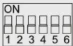
(6) 2-Position DIP Switch: Positions 1 and 2: Audio, Positions 3 and 4: Color, Positions 5 and 6: Format
Connectors — Input: (1) HDMI female;
Output: (1) HDMI female; Power: (1) 5-VDC barrel connector
Indicators — (1) Multiple-color Status LED
Power Supply — 5 VDC
Size — 0.9"H x 2"W x 3.2"D (2.2 x 5.1 x 8 cm)
Weight — 0.2 lb. (0.1 kg)
2. Overview
2.1 Introduction
The HDMI EDID Ghost stores and emulates your display's Extended Display Identification Data (EDID) information for optimal video resolution. EDID contains information about manufacturer name and serial number, product type, maximum image size, color characteristics, factory preset timings, frequency range limits, etc. If your display's EDID is not available, the EDID Ghost provides dedicated EDID data that perfectly matches your screen with the device you attach it to. The HDCP pass-through feature allows the unit to pass through HDCP encryption from your source device to your HDCP display without changing anything.
Use the EDID Ghost function to read and reserve the EDID of your displays. The EDID Emulation function enables you to emulate EDID information to display the optimum video resolution. The Ghost can alternatively apply the default or the copied EDID for the connected displays. Plus, it can modify the EDID and upload the revised EDID to displays.
2.2 Features
- EDID learning (read/store) functions prevent computers from deactivating inactive HDMI ports.
- Unique audio inventory features provide 2ch./5.1ch./7.1ch. audio EDID learning, best for home theater system applications
- Innovative technology integrates the emulated EDID parameters and the display's HDCP parameters.
- The rotary switch enables you to manually select video resolutions.
-
Provides modes for different applications: PC Mode, AV Mode, and Memory Mode:
-
PC Mode—used for desktop and laptop systems.
- AV Mode—used for home theater AV applications.
- Memory Mode—used to reserve your video/audio system's EDID information.
- Supports professional AV performance configuration, such as distinctive 50-Hz/60-Hz frame rate and interlaced/progressive (non-interlaced) scanning system.
EDID Ghost (DDC Ghost)
- Read and store (record) the EDID from the connecting display to the video extension system.
- Handles different types of incoming EDID data reading.
- Stores up to 15 presets/records of EDID data.
EDID Emulation
- Emulates EDID information to display the optimum video resolution.
- Provides EDID data if a display's EDID is not available.
- Alternatively applies the default or the copied EDID for the connected display device.
- Has selectable EDID functions for multimedia system integration.
• Supports a DVI signal. - Selectable scan mode and frame rate combined with optional video resolution enables flexible uses of your displays.
2.3 What's Included
Your package should include the following items. If anything is missing or damaged, contact Black Box Technical Support at 724-746-5500 or info@blackbox.com.
• (1) HDMI EDID Ghost
• (1) USB power cable
• (1) printed quick start guide
• (1) CD containing this user's manual in PDF format
• (1) set of foot pads
2.4 Optional Items
- Magnetic foot pad with necessary screws
CAUTION: Avoid locating the magnetic foot pad near any strong sources of electromagnetic radiation, such as CRT monitors, high-power electric cabling, audio equipment, and tape recorders.
- HDMI-to-DVI adapter for DVI applications.
NOTES:
Only use good quality connection cables to avoid interference.
Place cables away from fluorescent lights, air conditioners, and machines that are likely to generate electrical noise.
2.5 Hardware Description
Figure 2-1 shows the top, side, and bottom panels of the HDMI EDID Ghost. Table 2-1 describes its components.

Figure 2-1. HDMI EDID Ghost.
Table 2-1. HDMI EDID Ghost components.
| ID in Fig. 2-1 Component Description | |
| 1 Video connector | Connect the input side of the HDMI EDID Ghost to the HDMI extender, monitor, or switch. |
| 2 Video connector Connect the output side of the Ghost to the PC. | |
| 3 LED indicator | Blue: Power onRed: ErrorFlashes three times: Configuring HDMI EDIDFlashes twice: Configuring DVI EDID |
| 4 *Power jack Apply the proper power to the unit (optional). | |
| 5 Push button EDID Copy button | |
| 6 Rotary switch | Resolution selection in PC/AV Mode.Store presets in Memory Mode. |
| 7 DIP switch System configuration. | |
| 8 Slide switch Mode selection (PC/AV/Memory Mode). | |
*If the video source can supply enough power from the HDMI connector, it is optional to apply the power to the unit.
2.6 Scale of Rotary Switch
Table 2-2. PC-DVI Mode.
| Position Resolution | |
| 0 | Auto |
| 1 Manual | |
| 2 1024 x 768 | |
| 3 1280 x 720 | |
| 4 1280 x 1024 | |
| 5 1366 x 768 | |
| 6 1440 x 900 | |
| 7 1600 x 900 | |
| 8 1600 x 1200 | |
| 9 1680 x 1050 | |
| A 1920 x 1080 | |
| B 1920 x 1200 | |
| C 1280 x 800 | |
| D 2048 x 1152 | |
| E Reserved | |
| F Reserved | |
Table 2-3. PC-HDMI Mode.
| Position Resolution | |
| 0 | Auto |
| 1 Manual | |
| 2 1024 x 768 | |
| 3 1280 x 720 | |
| 4 1280 x 1024 | |
| 5 1366 x 768 | |
| 6 1440 x 900 | |
| 7 1600 x 900 | |
| 8 1600 x 1200 | |
| 9 1680 x 1050 | |
| A 1920 x 1080 | |
| B 1920 x 1200 | |
| C 1280 x 800 | |
| D 2048 x 1152 | |
| E 720 x 480 Learn color inventory | |
| F 720 x 576 Learn audio inventory | |
Table 2-4. Memory.
| Position Presets | |
| 0 | Preset 1 |
| 1 | Preset 2 |
| 2 | Preset 3 |
| 3 | Preset 4 |
| 4 | Preset 5 |
| 5 | Preset 6 |
| 6 | Preset 7 |
| 7 | Preset 8 |
| 8 | Preset 9 |
| 9 | Preset 10 |
| A | Preset 11 |
| B | Preset 12 |
| C | Preset 13 |
| D | Preset 14 |
| E | Preset 15 |
| F | — |
There are several options provided for AV Mode applications. Table 2-5 lists resolution, scanning system, and frame rate requirements.
Table 2-5. AV Mode applications.
| AV Mode Frame Rate: 50 Hz Frame Rate 60 Hz | |||||
| Position Resolution Interlaced (I) | Progressive (p) Non-interlaced | Interlaced (I) | Progressive (p) Non-interlaced | ||
| 0 | Auto | Automatically record connected display's EDID (ignore DIP Switch 1-6) | |||
| 1 Manual User recorded EDID (ignore DIP Switch 5-6) | |||||
| 2 1024 x 768 | 576i @ 50 Hz640 x 480p @ 60 Hz | 576p @ 50 Hz640 x 480p @ 60 Hz | 480i @ 60 Hz640 x 480p @ 60 Hz | 480p @ 60 Hz640 x 480p @ 60 Hz | |
| 3 1280 x 720 | 720p @ 50 Hz720p @ 24 Hz576i @ 50 Hz640 x 480p @ 60 Hz | 720p @ 50 Hz720p @ 24 Hz576p @ 50 Hz640 x 480p @ 60 Hz | 720p @ 60 Hz720p @ 24 Hz480i @ 60 Hz640 x 480p @ 60 Hz | 720p @ 60 Hz720p @ 24 Hz480p @ 60 Hz640 x 480p @ 60 Hz | |
| 4 1280 x 1024 | |||||
| 5 1366 x 768 | |||||
| 6 1440 x 900 | |||||
| 7 1600 x 900 | |||||
| 8 1600 x 1200 | |||||
| 9 1680 x 1050 | |||||
| A 1920 x 1080 | 1080i @ 50 Hz1080p @ 24 Hz720p @ 50 Hz720p @ 24 Hz576i @ 50 Hz640 x 480p @ 60 Hz | 1080p @ 50 Hz1080p @ 24 Hz720p @ 50 Hz720p @ 24 Hz576p @ 50 Hz640 x 480p @ 60 Hz | 1080i @ 60 Hz1080p @ 24 Hz720p @ 60 Hz720p @ 24 Hz480i @ 60 Hz640 x 480p @ 50 Hz | 1080i @ 60 Hz1080p @ 24 Hz720p @ 60 Hz720p @ 24 Hz480p @ 60 Hz640 x 480p @ 50 Hz | |
| B 1920 x 1200 | |||||
| C 1280 x 800 | 576i @ 50 Hz640 x 480p @ 60 Hz | 576p @ 50 Hz640 x 480p @ 60 Hz | 480i @ 60 Hz640 x 480p @ 60 Hz | 480p @ 60 Hz640 x 480p @ 60 Hz | |
| D 2048 x 1152 | 1080i @ 50 Hz1080p @ 24 Hz720p @ 50 Hz720p @ 24 Hz576i @ 50 Hz640 x 480p @ 60 Hz | 1080p @ 50 Hz1080p @ 24 Hz720p @ 50 Hz720p @ 50 Hz576p @ 50 Hz640 x 480p @ 60 Hz | 1080i @ 60 Hz1080p @ 24 Hz720p @ 60 Hz720p @ 24 Hz480i @ 60 Hz640 x 480p @ 60 Hz | 1080p @ 60 Hz1080p @ 24 Hz720p @ 60 Hz720p @ 24 Hz480p @ 60 Hz640 x 480p @ 60 Hz | |
| E 720 x 480 | 480i @ 50 Hz640 x 480p @ 60 Hz | 480p @ 50 Hz640 x 480p @ 60 Hz | 480i @ 60 Hz640 x 480p @ 60 Hz | 480p @ 60 Hz640 x 480p @ 60 Hz | |
| F 720 x 576 | 576i @ 50 Hz640 x 480p @ 60 Hz | 575p @ 50 Hz640 x 480p @ 60 Hz | 480i @ 60 Hz640 x 480p @ 60 Hz | 480p @ 60 Hz640 x 480p @ 60 Hz | |
3. Basic Operation
3.1 EDID Copy (EDID Ghost)
In some cases display problems may occur because of incorrect EDID communication between the display monitor and the unit or inappropriate EDID data programmed by display manufacturers. This function allows the system to copy EDID from EDID compliant displays. However, some devices may require system reboot after adjustment.
3.1.1 PC/AV/Memory Mode
For different applications, we recommend that you apply PC Mode to a desktop or laptop system. For a home theater AV application, use AV Mode because it may need more specific settings. In Memory mode, the Ghost can store and perform the recorded video EDID information.
3.1.2 Inventory y
An inventory is a storage system for accumulating a huge mass of EDID data. Users may copy and reserve your display's EDID in the Ghost. For different uses, the HDMI EDID Ghost provides delicate types of inventory, such as audio inventory, video-color inventory, and full EDID inventory. Once recorded, users can apply these EDID data to other displays.
Users may copy whole EDID information from EDID-compliant displays in Memory Mode. However, if you own advanced HDMI displays, like 7.1 ch. Home Theater AV Receiver and Full HD monitors, when switching to a specific position, this function enables you to copy audio EDID from different HDMI monitors or amplifiers for advanced uses.
Table 3-1. EDID settings.
| Name Function | |
| Audio EDID | audio channel |
| Video EDID | resolution, frame rate, scanning system, color space |
| Whole EDID | Audio EDID + Video EDID |

Figure 3-1. DIP switch settings for inventory.
3.2 EDID Copy Operation Steps
STEP 1. Set all switches to the correct positions (see Table 3-2).
Table 4-10. DIP switch settings.
| Function Slide Switch | Rotary Switch DIP Switch (1-6) | ||
 |  | ||
| Copy EDID (Whole) | PC/AV | 0 (Auto) | — |
| 1 (Manual) | — | ||
| Memory 0-9, A-E (15 presets for storage) | — | ||
| Copy EDID (Video–Color) | PC/AV E | 3 (ON) and 4 (ON) | |
| Copy EDID (Audio) | PC/AV F | 1 (ON) and 2 (ON) | |
| Memory F | 1 (ON) and 2 (ON)1 (ON) and 2 (OFF)1 (OFF) and 2 (ON)1 (OFF) and 2 (OFF)(4 presets for storage) | ||
NOTE: According to different copy methods, the system provides 1, 4, or 15 records for copied EDID storage. These data can be applied to EDID Emulation. See Chapter 4, Advanced Operation, for more details.
STEP 2. Apply power to the unit (if the source cannot supply enough power).
STEP 3. Connect display to Monitor Port (Video Out) on the unit and power on the display.
STEP 4. Press the "EDID Copy" button and release the button RIGHT AFTER the LED flashes green.
STEP 5. The LED flashes red and green alternately and then it lights blue, indicating that the copy is successful.
Otherwise, if the LED flashes RED, it means one or more of the following:
a. The monitor is not properly connected.
b. The monitor is not powered on.
c. EDID data of the monitor is not applicable.
(The idle time-out is 20 seconds.)
4. Advanced Operation
4.1 EDID Emulation
If your display's EDID is not available, the EDID Ghost provides a default profile that you can use. Users may apply the system-provided data or user-recorded EDID (see Chapter 3, Basic Operation) to the display in a few simple steps. However, some devices may need system reboot after adjustment.
The PC, AV, and Memory modes are provided for multiple purposes. The following statements describe each mode and its functions, and also provide operation steps.
4.1.1 PC Mode System Configuration
Computer display devices can sometimes lose EDID, so you can't get video from your notebook PC to external displays. To fix these problems, set the Slide Switch on the unit to PC Mode.

Figure 4-1. DIP switch settings for DVI mode and HDMI mode.
4.1.1.1 PC-DVI Mode
The unit supports both DVI and HDMI video signals. With an HDMI interface, this DVI mode will not carry audio channel. To display a DVI signal, set DIP Switch 6 to ON (UP). For DVI video resolution, see Section 2.6, Scale of Rotary Switch.
a) Slide switch: PC Mode
b) Rotary switch: See scale of rotary switch (Table 2-2).
c) DIP switch: ON (UP)/OFF (DOWN)

Figure 4-2. DIP switch settings for DVI mode.
NOTE: Rotary Switch:
Position 0: Automatically record connected display's EDID (ignore DIP switch 1–5).
Position 1: Require EDID Copy performance in advance.
4.1.1.2 PC-HDMI Mode
In HDMI mode, audio signal is embedded. To display the HDMI signal, set DIP Switch 6 to OFF (DOWN).
NOTE: If there's no copied information, the system will automatically set to factory default. Rotary Switch position "1" requires EDID Copy performance in advance and only uses HDMI recorded data.
a) Slide switch: PC Mode.
b) Rotary switch: See scale of rotary switch (Table 2-3).
c) DIP switch: ON (UP)/OFF (DOWN)

Figure 4-3. DIP switch settings for HDMI mode.
Table 4-1. DIP switch Positions 1 and 2 settings.
| DIP Switch Audio | Setting | |
| 1 | 2 | |
| ON ON Inventory | ||
| ON OFF 7.1 CH | ||
| OFF ON 5.1 CH | ||
| OFF OFF 2 CH | ||
Table 4-2. DIP switch Positions 3 and 4 settings.
| DIP Switch Color | Setting | |
| 3 | 4 | |
| ON ON Inventory | ||
| ON OFF RGB only | ||
| OFF ON +YCbCr | ||
| OFF OFF +Deep Color | ||
NOTE: Rotary switch:
Position 0: Automatically record connected display's EDID (ignore DIP switch 1–5).
Position 1: Require EDID Copy performance in advance.
4.1.2 AV Mode System Configuration
When using AV devices, such as Blu-ray DVD players, game consoles, and HD set-top boxes that are connected to projectors, LCD displays, and digital TVs, users may experience a few issues. For example, hue error or color mismatch caused by incorrect color space may occur. Inaccurate audio formats result in 2ch audio rather than 7.1ch, or inexact video resolution displays 480p instead of 1080p. You can solve these problems by adopting AV Mode.
a) Set the slide switch to AV Mode.
b) Rotary switch: See scale of rotary switch (Table 2-5).
c) DIP switch: ON (UP)/OFF (DOWN)

Figure 4-4. AV mode DIP switch settings.
Table 4-3. DIP switch Positions 1 and 2 Audio settings.
| DIP Switch Position | Setting | |
| 1 | 2 | |
| ON ON Inventory | ||
| ON OFF 7.1 CH | ||
| OFF ON 5.1 CH | ||
| OFF OFF 2 CH | ||
Table 4-4. DIP switch Positions 3 and 4 Color settings.
| DIP Switch Position | Setting | |
| 1 | 2 | |
| ON ON Inventory | ||
| ON OFF RGB only | ||
| OFF ON +YCbCr | ||
| OFF OFF +Deep Color | ||
Table 4-5. DIP switch scanning system.
| DIP Switch Position | Setting |
| 5 | |
| ON Interlaced | |
| OFF Progressive (Non-interlaced) | |
Table 4-6. DIP switch scan rate.
| DIP Switch Position | Setting |
| 6 | |
| ON 50 Hz | |
| OFF 60 Hz |
NOTE: Rotary switch:
Position 0: Automatically record connected display's EDID (ignore DIP switch 1–6).
Position 1: Require EDID Copy performance in advance (ignore DIP switch 5–6).
NOTE: Users may copy audio and/or color information (HDMI source only) for further uses.
4.1.3 Memory Mode System Configuration
Users may apply recorded EDID data to your display for further uses. In Memory mode, the unit can perform the recorded video EDID with or without carrying audio information. Setting DIP switch 6 to "ON" enables users to use recorded video EDID combined with audio EDID in audio inventory to output performance.
If there's no copied EDID information reserved, the system will automatically set to factory default.
a) Slide switch: Memory Mode
b) Rotary switch: 0–9, A–E (15 presets for storage; see Figure 4-5).
c) DIP switch: ON (UP)/OFF (DOWN)

Figure 4-5. DIP switch Memory Mode System Configuration.
Table 4-7. DIP switch audio.
| DIP Switch Position | ||
| 1 | 2 | Setting |
| ON ON Audio Inventory 0 | ||
| ON OFF Audio Inventory 1 | ||
| OFF ON Audio Inventory 2 | ||
| OFF OFF Audio Inventory 3 | ||
Table 4-8. DIP switch Recall.
| DIP Switch Position | |
| 6 | Setting |
| ON Combo type: Recall audio data from Audio Inventory 0–3 and other datas from Table 2-4. | |
| OFF Non-combo type: Recall whole EDID data from Table 2-4. | |
NOTE: Inventory 0–3 needs EDID Copy performance in advance.
4.2 EDID Emulation Operation Steps
STEP 1: Set the slide switch to PC/AV/Memory Mode.
STEP 2: Connect the video source and display to the unit.
STEP 3: Apply power to the unit (if the source does not supply enough power).
STEP 4: Set all switches to the desired positions (see Table 4-9).
Table 4-9. EDID Emulation settings.
| Function Slide Switch | Rotary Switch DIP Switch (1-6) | |
 |  | |
| For DVI display/PC PC 0-F (see Table 2-2) | See Figure 4-2 | |
| For HDMI display/PC PC 0-F (see Table 2-3) | See Figure 4-3 | |
| For HDMI display/AV AV 0-F (see Table 2-5) | See Figure 4-4 | |
| Combo Type Memory 0-E (see Table 2-4) | See Figure 4-5 and Table 4-8 | |
| Non-combo Type Memory 0-E (see Table 2-4) | See Figure 4-5 and Table 4-8 | |
NOTES:
- Hold/wait for 2–3 seconds after adjustment steps.
- Some devices may need system reboot after adjustment.
4.3 Factory Default Setting
4.3.1 One-by-One Individually
This function enables each unit to reset to factory defaults.
STEP 1: Set all switches to the designated positions. (See Table 4-10.)
Table 4-10. DIP switch settings.
| Function Slide Switch | Rotary Switch DIP Switch (1-6) | ||
 |  | ||
| Copy EDID (Whole) | PC/AV | 0 (Auto) | — |
| 1 (Manual) | — | ||
| Memory 0-9, A-E (15 presets for storage) | — | ||
| Copy EDID (Video-Color) | PC/AV E | 3 (ON) and 4 (ON) | |
| Copy EDID (Audio) | PC/AV F | 1 (ON) and 2 (ON) | |
| Memory F | 1 (ON) and 2 (ON)1 (ON) and 2 (OFF)1 (OFF) and 2 (ON)1 (OFF) and 2 (OFF)(4 presets for storage) | ||
STEP 2: Apply power to the unit (if the source cannot supply enough power)
STEP 3: Press the button "EDID Copy" and release the button RIGHT AFTER the LED flashes RED.
STEP 4: The LED flashes red and green alternately and then it lights blue indicating that the copy is successful.
If you keep pressing the "EDID Copy" button for 20–25 seconds, it will light white and all EDIDs will be cleared.
4.3.2 All Records of EDID
No matter which position the switches are in, this function will have ALL records return to factory default.
STEP 1: Apply power to the unit (if the source cannot apply enough power).
STEP 2: Press the "EDID Copy" button for 20–25 seconds and release the button right after the LED flashes white.
STEP 3: The LED flashes red and green alternately and then it lights blue, indicating that the copy is successful.
Otherwise, if you keep pressing the "EDID Copy" button for more than 25 seconds, it will light blue, indicating a failed setting. Go to Step 3 again.
Appendix. Tables
A.1 Scale of Rotary Switch
A.1.1 Rotary Switch — PC-DVI Mode
Table A-1. PC-DVI Mode.
| Position Resolution | |
| 0 | Auto |
| 1 Manual | |
| 2 1024 x 768 | |
| 3 1280 x 720 | |
| 4 1280 x 1024 | |
| 5 1366 x 768 | |
| 6 1440 x 900 | |
| 7 1600 x 900 | |
| 8 1600 x 1200 | |
| 9 1680 x 1050 | |
| A 1920 x 1080 | |
| B 1920 x 1200 | |
| C 1280 x 800 | |
| D 2048 x 1152 | |
| E Reserved | |
| F Reserved | |
A.1.2 Rotary Switch—PC-HDMI Mode
Table A-2. PC-HDMIs Mode.
| Position Resolution | |
| 0 | Auto |
| 1 Manual | |
| 2 1024 x 768 | |
| 3 1280 x 720 | |
| 4 1280 x 1024 | |
| 5 1366 x 768 | |
| 6 1440 x 900 | |
| 7 1600 x 900 | |
| 8 1600 x 1200 | |
| 9 1680 x 1050 | |
| A 1920 x 1080 | |
| B 1920 x 1200 | |
| C 1280 x 800 | |
| D 2048 x 1152 | |
| E 720 x 480 Learn color inventory | |
| F 720 x 576 Learn audio inventory | |
A.1.3 Rotary Switch—Memory Mode
Table A-3. Memory.
| Position Presets | |
| 0 | Preset 1 |
| 1 | Preset 2 |
| 2 | Preset 3 |
| 3 | Preset 4 |
| 4 | Preset 5 |
| 5 | Preset 6 |
| 6 | Preset 7 |
| 7 | Preset 8 |
| 8 | Preset 9 |
| 9 | Preset 10 |
| A | Preset 11 |
| B | Preset 12 |
| C | Preset 13 |
| D | Preset 14 |
| E | Preset 15 |
| F | — |
A.1.4 Rotary Switch—AV Mode
Table A-4. AV Mode applications.
| AV Mode Frame Rate: 50 Hz Frame Rate 60 Hz | |||||
| Position Resolution Interlaced (I) | Progressive (p) Non-interlaced | Interlaced (I) | Progressive (p) Non-interlaced | ||
| 0 | Auto | Automatically record connected display's EDID (ignore DIP switch 1-6) | |||
| 1 Manual User recorded EDID (ignore DIP switch 5-6) | |||||
| 2 1024 x 768 | 576i @ 50 Hz640 x 480p @ 60 Hz | 576p @ 50 Hz640 x 480p @ 60 Hz | 480i @ 60 Hz640 x 480p @ 60 Hz | 480p @ 60 Hz640 x 480p @ 60 Hz | |
| 3 1280 x 720 | 720p @ 50 Hz720p @ 24 Hz576i @ 50 Hz640 x 480p @ 60 Hz | 720p @ 50 Hz720p @ 24 Hz576p @ 50 Hz640 x 480p @ 60 Hz | 720p @ 60 Hz720p @ 24 Hz480i @ 60 Hz640 x 480p @ 60 Hz | 720p @ 60 Hz720p @ 24 Hz480p @ 60 Hz640 x 480p @ 60 Hz | |
| 4 1280 x 1024 | |||||
| 5 1366 x 768 | |||||
| 6 1440 x 900 | |||||
| 7 1600 x 900 | |||||
| 8 1600 x 1200 | |||||
| 9 1680 x 1050 | |||||
| A 1920 x 1080 | 1080i @ 50 Hz1080p @ 24 Hz720p @ 50 Hz720p @ 24 Hz576i @ 50 Hz640 x 480p @ 60 Hz | 1080p @ 50 Hz1080p @ 24 Hz720p @ 50 Hz720p @ 24 Hz576p @ 50 Hz640 x 480p @ 60 Hz | 1080i @ 60 Hz1080p @ 24 Hz720p @ 60 Hz720p @ 24 Hz480i @ 60 Hz640 x 480p @ 50 Hz | 1080i @ 60 Hz1080p @ 24 Hz720p @ 60 Hz720p @ 24 Hz480p @ 60 Hz640 x 480p @ 50 Hz | |
| B 1920 x 1200 | |||||
| C 1280 x 800 | 576i @ 50 Hz640 x 480p @ 60 Hz | 576p @ 50 Hz640 x 480p @ 60 Hz | 480i @ 60 Hz640 x 480p @ 60 Hz | 480p @ 60 Hz640 x 480p @ 60 Hz | |
| D 2048 x 1152 | 1080i @ 50 Hz1080p @ 24 Hz720p @ 50 Hz720p @ 24 Hz576i @ 50 Hz640 x 480p @ 60 Hz | 1080p @ 50 Hz1080p @ 24 Hz720p @ 50 Hz720p @ 50 Hz576p @ 50 Hz640 x 480p @ 60 Hz | 1080i @ 60 Hz1080p @ 24 Hz720p @ 60 Hz720p @ 24 Hz480i @ 60 Hz640 x 480p @ 60 Hz | 1080p @ 60 Hz1080p @ 24 Hz720p @ 60 Hz720p @ 24 Hz480p @ 60 Hz640 x 480p @ 60 Hz | |
| E 720 x 480 | 480i @ 50 Hz640 x 480p @ 60 Hz | 480p @ 50 Hz640 x 480p @ 60 Hz | 480i @ 60 Hz640 x 480p @ 60 Hz | 480p @ 60 Hz640 x 480p @ 60 Hz | |
| F 720 x 576 | 576i @ 50 Hz640 x 480p @ 60 Hz | 575p @ 50 Hz640 x 480p @ 60 Hz | 480i @ 60 Hz640 x 480p @ 60 Hz | 480p @ 60 Hz640 x 480p @ 60 Hz | |
A.2 EDID Copy
Table 4-10. DIP switch settings.
| Function Slide Switch | Rotary Switch DIP Switch (1-6) | ||
 |  | ||
| Copy EDID (Whole) | PC/AV | 0 (Auto) | — |
| 1 (Manual) | — | ||
| Memory 0-9, A-E (15 presets for storage) | — | ||
| Copy EDID (Video-Color) | PC/AV E | 3 (ON) and 4 (ON) | |
| Copy EDID (Audio) | PC/AV F | 1 (ON) and 2 (ON) | |
| Memory F | 1 (ON) and 2 (ON)1 (ON) and 2 (OFF)1 (OFF) and 2 (ON)1 (OFF) and 2 (OFF)(4 presets for storage) | ||
A.3 PC-DVI Mode
a) Slide switch: PC Mode
b) Rotary switch: See scale of rotary switch (Table 2-2).
c) DIP switch: ON (UP)/OFF (DOWN)

Figure A-1. DIP switch settings for DVI mode.
NOTE: Rotary Switch:
Position 0: Automatically record connected display's EDID (ignore DIP switch 1–5).
Position 1: Require EDID Copy performance in advance.
A.4 PC-HDMI Mode
a) Slide switch: PC Mode.
b) Rotary switch: See scale of rotary switch (Table 2-3).
c) DIP switch: ON (UP)/OFF (DOWN)

Figure A-2. DIP switch settings for HDMI mode.
Table A-6. DIP switch Positions 1 and 2 settings.
| DIP Switch Audio | Setting | |
| 1 | 2 | |
| ON ON Inventory | ||
| ON OFF 7.1 CH | ||
| OFF ON 5.1 CH | ||
| OFF OFF 2 CH | ||
Table A-7. DIP switch Positions 3 and 4 settings.
| DIP Switch Color | Setting | |
| 3 | 4 | |
| ON ON Inventory | ||
| ON OFF RGB only | ||
| OFF ON +YCbCr | ||
| OFF OFF +Deep Color | ||
NOTE: Rotary switch:
Position 0: Automatically record connected display's EDID (ignore DIP switch 1–5).
Position 1: Require EDID Copy performance in advance.
A.5 AV Mode System Configuration
a) Set the slide switch to AV Mode.
b) Rotary switch: See scale of rotary switch (Table 2-5).
c) DIP switch: ON (UP)/OFF (DOWN)

Figure A-3. AV mode DIP switch settings.
Table A-8. DIP switch Positions 1 and 2 Audio settings.
| DIP Switch Position | Setting | |
| 1 | 2 | |
| ON ON Inventory | ||
| ON OFF 7.1 CH | ||
| OFF ON 5.1 CH | ||
| OFF OFF 2 CH | ||
Table A-9. DIP switch Positions 3 and 4 Color settings.
| DIP Switch Position | Setting | |
| 1 | 2 | |
| ON ON Inventory | ||
| ON OFF RGB only | ||
| OFF ON +YCbCr | ||
| OFF OFF +Deep Color | ||
Table A-10. DIP switch scanning system.
| DIP Switch Position | Setting |
| 5 | |
| ON Interlaced | |
| OFF Progressive (Non-interlaced) | |
Table A-11. DIP switch scan rate.
| DIP Switch Position | Setting |
| 6 | |
| ON 50 Hz | |
| OFF 60 Hz |
NOTE: Rotary switch:
Position 0: Automatically record connected display's EDID (ignore DIP switch 1–6).
Position 1: Require EDID Copy performance in advance (ignore DIP switch 5–6).
NOTE: Users may copy audio and/or color information (HDMI source only) for further uses.
A.6 Memory Mode System Configuration
a) Slide switch: Memory Mode
b) Rotary switch: 0–9, A–E (15 presets for storage; see Figure A-4).
c) DIP switch: ON (UP)/OFF (DOWN)

Figure A-4. DIP switch Memory Mode System Configuration.
Table A-11. DIP switch audio.
| DIP Switch Position | ||
| 1 | 2 | Setting |
| ON ON Audio Inventory 0 | ||
| ON OFF Audio Inventory 1 | ||
| OFF ON Audio Inventory 2 | ||
| OFF OFF Audio Inventory 3 | ||
Table A-12. DIP switch Recall.
| DIP Switch Position | |
| 6 | Setting |
| ON Combo type: Recall audio data from Audio Inventory 0–3 and other datas from Table 2-4. | |
| OFF Non-combo type: Recall whole EDID data from Table 2-4. | |
NOTE: Inventory 0–3 needs EDID Copy performance in advance.
A.7 EDID Emulation Operation Steps
Table A-13. EDID Emulation settings.
| Function Slide Switch | Rotary Switch DIP Switch (1-6) | |
 |  | |
| For DVI display/PC PC 0-F (see Table 2-2) | See Figure 4-2 | |
| For HDMI display/PC PC 0-F (see Table 2-3) | See Figure 4-3 | |
| For HDMI display/AV AV 0-F (see Table 2-5) | See Figure 4-4 | |
| Combo Type Memory 0-E (see Table 2-4) | See Figure 4-5 and Table 4-8 | |
| Non-combo Type Memory 0-E (see Table 2-4) | See Figure 4-5 and Table 4-8 | |
NOTES:
- Hold/wait for 2–3 seconds after adjustment steps.
- Some devices may need system reboot after adjustment.
A.8 Factory Default Setting
Table 4-10. DIP switch settings.
| Function Slide Switch | Rotary Switch DIP Switch (1-6) | ||
 |  | ||
| Copy EDID (Whole) | PC/AV | 0 (Auto) | — |
| 1 (Manual) | — | ||
| Memory 0-9, A-E (15 presets for storage) | — | ||
| Copy EDID (Video-Color) | PC/AV E | 3 (ON) and 4 (ON) | |
| Copy EDID (Audio) | PC/AV F | 1 (ON) and 2 (ON) | |
| Memory F | 1 (ON) and 2 (ON)1 (ON) and 2 (OFF)1 (OFF) and 2 (ON)1 (OFF) and 2 (OFF)(4 presets for storage) | ||
Black Box Tech Support: FREE! Live. 24/7.
Tech support the way it should be.

natural_image
Close-up portrait of a smiling man with short hair holding a small object, against a blue gradient background (no text or symbols visible)Great tech support is just 30 seconds away at 724-746-5500 or blackbox.com.

BLACK BOX®
NETWORK SERVICES
About Black Box
Black Box provides an extensive range of networking and infrastructure products. You'll find everything from cabinets and racks and power and surge protection products to media converters and Ethernet switches all supported by free, live 24/7 Tech support available in 30 seconds or less.
© Copyright 2013. Black Box Corporation. All rights reserved.s
VG-HDMI user manual, version 1
- Trademarks Used in this Manual
- Federal Communications Commission and Industry Canada Radio Frequency Interference Statements
- Specifications
- Overview
- Introduction
- Features
- EDID Ghost (DDC Ghost)
- EDID Emulation
- What's Included
- Optional Items
- Hardware Description
- Scale of Rotary Switch
- Basic Operation
- EDID Copy (EDID Ghost)
- PC/AV/Memory Mode
- Inventory y
- EDID Copy Operation Steps
- Advanced Operation
- EDID Emulation
- PC Mode System Configuration
- PC-DVI Mode
- PC-HDMI Mode
- AV Mode System Configuration
- Memory Mode System Configuration
- EDID Emulation Operation Steps
- NOTES:
- Factory Default Setting
- One-by-One Individually
- All Records of EDID
- Appendix. Tables
- A.1 Scale of Rotary Switch
- A.1.1 Rotary Switch — PC-DVI Mode
- A.1.2 Rotary Switch—PC-HDMI Mode
- A.1.3 Rotary Switch—Memory Mode
- A.1.4 Rotary Switch—AV Mode
- A.2 EDID Copy
- A.3 PC-DVI Mode
- A.4 PC-HDMI Mode
- A.5 AV Mode System Configuration
- A.6 Memory Mode System Configuration
- A.7 EDID Emulation Operation Steps
- A.8 Factory Default Setting
- Black Box Tech Support: FREE! Live. 24/7.
- BLACK BOX®
- NETWORK SERVICES
- About Black Box
Brand : Black Box
Model : VG-HDMI
Category : Video accessory