AT-HDR-CAT-8 - Câble Atlona - Free user manual and instructions
Find the device manual for free AT-HDR-CAT-8 Atlona in PDF.

User questions about AT-HDR-CAT-8 Atlona
0 question about this device. Answer the ones you know or ask your own.
Ask a new question about this device
Download the instructions for your Câble in PDF format for free! Find your manual AT-HDR-CAT-8 - Atlona and take your electronic device back in hand. On this page are published all the documents necessary for the use of your device. AT-HDR-CAT-8 by Atlona.
USER MANUAL AT-HDR-CAT-8 Atlona
| Version Release Date Notes | ||
| 3 Jun 2023 - | Corrections to package includes- Minor corrections to spec table (does not change product behavior / performance) | |
Sales, Marketing, and Customer Support
Main Office
Atlona Incorporated
70 Daggett Drive
San Jose, CA 95134
United States
Office: +1.408.962.0515
Sales and Customer Service Hours
Monday - Friday: 6:00 a.m. - 4:30 p.m. (PST)
https://atlona.com/
International Headquarters
Atlona International AG
Tödistrasse 18
8002 Zürich
Switzerland
Office: +41.43.508.4321
Sales and Customer Service Hours
Monday - Friday: 09:00 - 17:00 (UTC +1)
Operating Notes

IMPORTANT: Visit https://www.ationa.com/product/AT-HDR-CAT-4 for the latest firmware updates and User Manual.
Warranty

text_image
QR code image containing encoded data, no visible human-readable textTo view the product warranty, use the following link or QR code:
https://atlona.com/warranty/.
Safety and Certification
CAUTION
RISK OF ELECTRIC SHOCK
DO NOT OPEN
CAUTION: TO REDUCT THE RISK OF
ELECTRIC SHOCK
DO NOT OPEN ENCLOSURE OR EXPOSE
TO RAIN OR MOISTURE.
NO USER-SERVICEABLE PARTS
INSIDE REFER SERVICING TO
QUALIFIED SERVICE PERSONNEL.

The exclamation point within an equilateral triangle is intended to alert the user to the presence of important operating and maintenance instructions in the literature accompanying the product.

The information bubble is intended to alert the user to helpful or optional operational instructions in the literature accompanying the product.
- Read these instructions.
- Keep these instructions.
- Heed all warnings.
- Follow all instructions.
- Do not use this product near water.
- Clean only with a dry cloth.
- Do not block any ventilation openings. Install in accordance with the manufacturer's instructions.
-
Do not install or place this product near any heat sources such as radiators, heat registers, stoves, or other apparatus (including amplifiers) that produce heat.
-
Do not defeat the safety purpose of a polarized or grounding-type plug. A polarized plug has two blades with one wider than the other. A grounding type plug has two blades and a third grounding prong. The wide blade or the third prong are provided for your safety. If the provided plug does not fit into your outlet, consult an electrician for replacement of the obsolete outlet.
- Protect the power cord from being walked on or pinched particularly at plugs, convenience receptacles, and the point where they exit from the product.
- Only use attachments/accessories specified by Atlona.
- To reduce the risk of electric shock and/or damage to this product, never handle or touch this unit or power cord if your hands are wet or damp. Do not expose this product to rain or moisture.
- Unplug this product during lightning storms or when unused for long periods of time.
- Refer all servicing to qualified service personnel. Servicing is required when the product has been damaged in any way, such as power-supply cord or plug is damaged, liquid has been spilled or objects have fallen into the product, the product has been exposed to rain or moisture, does not operate normally, or has been dropped.


FCC Compliance
FCC Compliance and Advisory Statement: This hardware device complies with Part 15 of the FCC rules. Operation is subject to the following two conditions: 1) this device may not cause harmful interference, and 2) this device must accept any interference received including interference that may cause undesired operation. This equipment has been tested and found to comply with the limits for a Class A digital device, pursuant to Part 15 of the FCC Rules. These limits are designed to provide reasonable protection against harmful interference in a commercial installation. This equipment generates, uses, and can radiate radio frequency energy and, if not installed or used in accordance with the instructions, may cause harmful interference to radio communications. However there is no guarantee that interference will not occur in a particular installation. If this equipment does cause harmful interference to radio or television reception, which can be determined by turning the equipment off and on, the user is encouraged to try to correct the interference by one or more of the following measures: 1) reorient or relocate the receiving antenna; 2) increase the separation between the equipment and the receiver; 3) connect the equipment to an outlet on a circuit different from that to which the receiver is connected; 4) consult the dealer or an experienced radio/TV technician for help. Any changes or modifications not expressly approved by the party responsible for compliance could void the user's authority to operate the equipment. Where shielded interface cables have been provided with the product or specified additional components or accessories elsewhere defined to be used with the installation of the product, they must be used in order to ensure compliance with FCC regulations.
Copyright, Trademark, and Registration
© 2023 Atlona Inc. All rights reserved. "Atlona" and the Atlona logo are registered trademarks of Atlona Inc. Pricing, specifications and availability subject to change without notice. Actual products, product images, and online product images may vary from images shown here.

The terms HDMI, HDMI High-Definition Multimedia Interface, and the HDMI Logo are trademarks or registered trademarks of HDMI licensing Administrator, Inc.
Dolby, Dolby Atmos, and the double-D symbol are registered trademarks of Dolby Laboratories Licensing Corporation.
For DTS patents, see http://patents.dts.com. Manufactured under license from DTS, Inc. DTS, the Symbol, DTS and the Symbol together, and Digital Surround are registered trademarks and/or trademarks of DTS, Inc. in the United States and/or other countries. © DTS, Inc. All Rights Reserved.
All other trademark(s), copyright(s), and registered technologies mentioned in this document are the properties of their respective owner(s).
Table of Contents
Introduction 7
Features 7
Package Contents 7
Panel Description 8
Front Panel 8
Back Panel 9
Connection Instructions 10
Connection Diagram 11
IP Configuration 12
Setting the IP Mode 12
Setting the IP Address Using Commands 13
Auto IP (APIPA) Mode 14
Device Operation 15
LED Indicators 15
Logging in to the Web Server 16
Login Registration 16
Logging in after Registration 17
Locking / Unlocking the Front Panel 18
Using the Front Panel 18
Using the Web Server 18
EDID Management 19
Learning an EDID using the Front Panel 19
Learning the EDID using the Web Server 20
Locking the EDID 20
Selecting EDID Presets 21
Changing Login Credentials 22
Changing the Username and Password 22
Controlling Audio Output 23
Audio Port Wiring 23
De-Embedding Audio 24
Adjusting the Volume Level 24
RS-232 Control 25
RS-232 Port Wiring 25
Pass-through mode 27
Control mode 28
IR Control 29
Controlling Display Devices 29
Controlling Source Devices 30
Power Button Modes 31
Normal Operation 31
Controlling Power on Sink Devices 32
Controlling Power on Sinks and the AT-HDR-CAT-4 34
Setting the Host Name 35
Resetting to Factory-Default Settings 36
Configuration and Management Interfaces 38
Web Server 38
Register page 38
Login page 39
Info page 40
A/V Settings page 41
RS-232 page 42
EDID page 43
Config page 44
HDBT page 45
System page 46
Table of Contents
Appendix
49
Updating the Firmware 49
Using the Web Server 49
Using USB 50
Default Settings 51
Specifications 52
Introduction
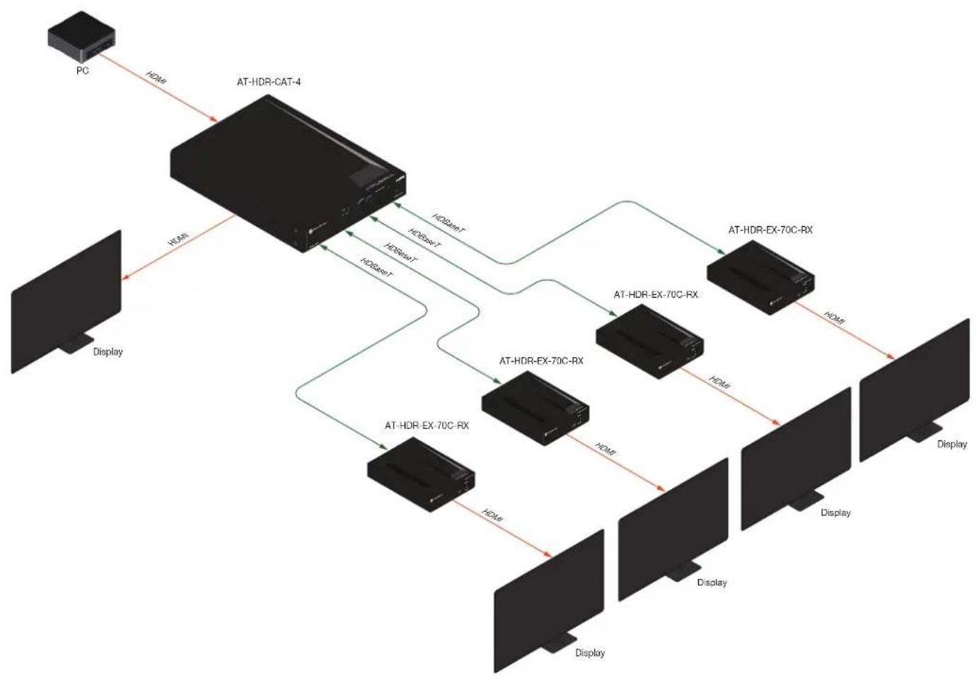
The Atlona AT-HDR-CAT-4 is a high dynamic range (HDR) distribution amplifier with one HDMI® input and four HDBaseT™ outputs. Each output transmits 4K/UHD video @ 60 Hz with 4:4:4 chroma sampling plus support for HDR formats, multi-channel audio, control signals, and power up to 130 ft. (40 m) or 1080p up to 230 ft. (70 m) over Category 6/6A cable. The HDR-CAT-4 features sophisticated integration capabilities designed for commercial AV distribution applications including HDMI pass-through, audio de-embedding, EDID management, CEC display control, RS-232 and IR control extension, remote power for receivers, and HDBaseT link testing. It offers compatibility with any TCP/IP or RS-232 control system and is housed in 1U, half-rack width enclosure with external universal power supply. The HDR-CAT-4 is ideal for sending HDR and 4K/60 4:4:4 content to AT-HDR-EX-70C-RX receivers.
Features
- 4K HDR distribution amplifier with one HDMI input and four HDBaseT outputs.
• Pass-through HDMI output to support local monitor.
• 4K/UHD capability @ 60 Hz with 4:4:4 chroma sampling. - Supports HDR10, HLG, and Dolby® Vision™ HDR formats.
- Features visually lossless compression with no latency to enable HDR and 4K/60 4:4:4 video signal extension over HDBaseT.
- HDBaseT outputs extend HDMI, control signals, and power up to 130 feet (40 meters) for 4K HDR or 230 feet (70 meters) for 1080p with Category 6/6A.
- Bidirectional RS-232 and IR control extension for each output.
- Remotely powers compatible receivers over HDBaseT.
- CEC display control sends display power on/off commands over HDBaseT using the power button, IP, or RS-232.
• Audio de-embedding to balanced analog output with volume control for integration with a separate audio system. - HDBaseT link test verifies cable, termination, and link quality for more reliable installations.
- Multi-channel audio pass-through.
- Cascade up to 8 units to expand system without compromising performance.
- Compliant with HDCP 2.2, the latest specification for passing protected content between devices.
- Manages EDID communications with the source through a display's EDID or internally stored EDID.
- Intuitive GUI-based configuration using integrated web server.
- Flexible control options via TCP/IP, RS-232, and IR with Atlona Velocity™ or third-party control systems.
- Front panel includes LEDs for power, HDBaseT link, and HDMI signal status information as well as buttons for power and EDID control.
- Compatible with HDR-EX-70C-RX receivers for 4K/60 4:4:4 HDR as well as AT-UHD-EX receivers for resolutions up to 4K60 4:2:0.
- 1U, half rack width enclosure with surface and rack mounting hardware included.
Package Contents
1 x AT-HDR-CAT-4
6 x 5-pin captive screw connectors
1 x 2-pin captive screw connector
1 x 48 V / 2.08 A power supply
1 x AC cord
1 x Long rack ear
1 x Short rack ear
2 x Mounting plates
4 x Mounting screws
4 x Rack screws
4 x Feet w/ rubber grips
Panel Description
Front Panel

text_image
ATLONA® HDMI IN OUT 1 2 3 5 6 HDBaseT LOCK INT LEARN HDMI AT-HDR-CAT-4 POWER FWEDID1 HDMI Indicators
Displays the status of the HDMI IN and HDMI OUT ports. When connected to a source or display (sink) device, respectively, the LED indicator will be blue.
2 HDBaseT Indicators
Displays the status of the HDBaseT OUT ports. When connected to an HDBaseT receiver, with an active sink, the LED indicator will be blue. If no active sink is connected, or the sink is powered off, then the indicator will not be illuminated.
3 LOCK
This LED will be blue when the unit is locked.
4 POWER
Press this button to power-on or place the unit into standby mode.
5 INT
This LED indicator will be blue when the unit is using an internal EDID.
6 LEARN
This LED indicator will flash when a downstream EDID is being read into memory.
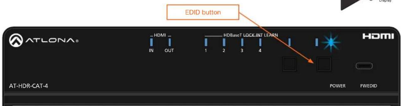
7 EDID
Press this button to switch between the internal (INT) and learned (LEARN) EDID modes.
8 FW
Connect a USB Type-A to USB-C cable from this port, to a computer, to update the firmware. Refer to Updating the Firmware (page 49) for more information.
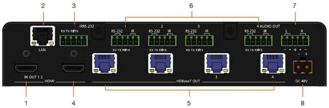
Back Panel
text_image
2 3 IRRS-232 1 2 3 4 AUDIO OUT LAN RX TX RRTX RS-232 IR RS-232 IR RS-232 IR RS-232 IR RS-232 IR L R IN OUT 1 2 HDMI HDBaseT OUT DC 48V 5 6 7 81 HDMI IN
Connect an HDMI cable from this port to a source device.
2 LAN
Connect an Ethernet cable from this port to the network.
3 RS-232 / IR (MASTER)
Connect a control system or other DTE device to this port to control the AT-HDR-CAT-4.
4 HDMI OUT
Connect an HDMI cable from this port to an HDMI input on a local display or an additional AT-HDR-CAT-4 unit.
5 HDBaseT OUT
Connect category cables from these ports to compatible receivers.
6 RS-232/IR 1 - 4
Connect a control system or other DTE device to these ports for pass-through zone control. Each of these ports uses the associated HDBaseT OUT port. This allows RS-232 command data to be sent to a display (sink) device connected to a compatible receiver.
7 AUDIO OUT
Connect the included 5-pin captive screw connector to this port and connect it to an audio amplifier, such as an AT-GAIN-60. Refer to Controlling Audio Output (page 23).
8 DC 48V
Connect the included power supply to this power receptacle.
Connection Instructions
- Connect an HDMI cable from a source to the HDMI IN port.
- Connect an HDMI cable from the HDMI OUT port to a local display.
- Connect up to four category cables from the HDBaseT OUT ports to compatible receivers. Refer to the table below for information on maximum cable length and supported resolutions.

IMPORTANT: Stranded or patch cable is not recommended due to performance issues. Sheilded cables are strongly recommended to minimize signal noise and interference.
| Cable 4K/UHD - Feet / Meters 1080p - Feet / Meters | ||||
| HDMI 15 5 30 10 | ||||
| CAT5e/6 115 35 200 60 | ||||
| CAT6a/7 130 40 230 70 | ||||
- Connect an Ethernet cable from the LAN port to the Local Area Network (LAN). This step will be required in order to access the built-in web server.
- Connect an RS-232 or IR cable from the control system to the RS-232/IR ports. Refer to RS-232 Control (page 25) and IR Control (page 29) for more information.
• MASTER RS-232/IR
Connecting to this port will provide direct control of the AT-HDR-CAT-4. Control can be performed using either RS-232 or electrical IR.
• RS-232/IR 1 - RS-232/IR 4
Each of these ports is associated to the respective HDBaseT OUT port. This allows RS-232 pass-through zone control of a display (sink) device that is connected to a compatible receiver. Control can be performed using RS-232 or electrical IR.
-
Connect an audio output device to the AUDIO OUT port. Refer to Controlling Audio Output (page 23) for more information.
-
Connect the included power supply to the DC 48V connector and connect the power cord to an available electrical outlet.
Installation
Connection Diagram
flowchart
graph TD
    PC["PC"] -->|HDMI| AT_HDR_CAT_4["AT-HDR-CAT-4"]
    PC -->|HDMI| Display1["Display"]
    AT_HDR_CAT_4 -->|HDMI+T| AT_HDR_EX-70C_RX["AT-HDR-EX-70C-RX"]
    AT_HDR_CAT_4 -->|HDMI+T| AT_HDR_EX-70C_RX
    AT_HDR_CAT_4 -->|HDMI+T| AT_HDR_EX-70C_RX
    AT_HDR_CAT_4 -->|HDMI+T| AT_HDR_EX-70C_RX
    AT_HDR_CAT_4 -->|HDMI+T| AT_HDR_EX-70C_RX
    AT_HDR_CAT_4 -->|HDMI+T| AT_HDR_EX-70C_RX

    subgraph AT_HDR_CAT_4
        A["PC"]
        B["Display"]
    end

    subgraph AT_HDR_EX-70C_RX
        C["AT-HDR-EX-70C-RX"]
        D["Display"]
    end

    subgraph AT_HDR_EX-70C_RX
        E["AT-HDR-EX-70C-RX"]
        F["Display"]
    end

    subgraph AT_HDR_EX-70C_RX
        G["AT-HDR-EX-70C-RX"]
        H["Display"]
    end

    subgraph AT_HDR_EX-70C_RX
        I["AT-HDR-EX-70C-RX"]
        J["Display"]
    end

    subgraph AT_HDR_EX-70C_RX
        K["AT-HDR-EX-70C-RX"]
        L["Display"]
    end

    subgraph AT_HDR_EX-70C_RX
        M["AT-HDR-EX-70C-RX"]
        N["Display"]
    end

    subgraph AT_HDR_EX-70C_RX
        O["AT-HDR-EX-70C-RX"]
        P["Display"]
    end

    subgraph AT_HDR_EX-70C_RX
        Q["AT-HDR-EX-70C-RX"]
        R["Display"]
    end

    subgraph AT_HDR_EX-70C_RX
        S["AT-HDR-EX-70C-RX"]
        T["Display"]
    end

    subgraph AT_HDR_EX-70C_RX
        U["AT-HDR-EX-70C-RX"]
        V["Display"]
    end

    subgraph AT_HDR_EX-70C_RX
        W["AT-HDR-EX-70C-RX"]
        X["Display"]
    end

    subgraph AT_HDR_EX-70C_RX
        Y["AT-HDR-EX-70C-RX"]
        Z["Display"]
    end

    subgraph AT_HDR_EX-70C_RX
        AA["AT-HDR-EX-70C-RX"]
        AB["Display"]
    end

    subgraph AT_HDR_EX-70C_RX
        AC["AT-HDR-EX-70C-RX"]
        AD["Display"]
    end

    subgraph AT_HDR_EX-70C_RX
        AE["AT-HDR-EX-70C-RX"]
        AF["Display"]
    end

    subgraph AT_HDR_EX-70C_RX
        AG["AT-HDR-EX-70C-RX"]
        AH["Display"]
    end

    subgraph AT_HDR_EX-70C_RX
        AI["AT-HDR-EX-70C-RX"]
        AJ["Display"]
    end

    subgraph AT_HDR_EX-70C_RX
        AK["AT-HDR-EX-70C-RX"]
        AL["Display"]
    end

    subgraph AT_HDR_EX-70C_RX
        AM["AT-HDR-EX-70C-RX"]
        AN["Display"]
    end

    subgraph AT_HDR_EX-70C_RX
        AO["AT-HDR-EX-70C-RX"]
        AP["Display"]
    end

    subgraph AT_HDR_EX-70C_RX
        AQ["AT-HDR-EX-70C-RX"]
        AR["Display"]
    end

    subgraph AT_HDR_EX-70C_RX
        AS["AT-HDR-EX-70C-RX"]
        AT["Display"]
    end

    subgraph AT_HDR_EX-70C_RX
        AU["AT-HDR-EX-70C-RX"]
        AV["Display"]
    end

    subgraph AT_HDR_EX-70C_RX
        AW["AT-HDR-EX-70C-RX"]
        AX["Display"]
    end

    subgraph AT_HDR_EX-70C_RX
        AY["AT-HDR-EX-70C-RX"]
        AZ["Display"]
    end

    subgraph AT_HDR_EX-70C_RX
        BA["AT-HDR-EX-70C-RX"]
        BB["Display"]
    end

    subgraph AT_HDR_EX-70C_RX
        BC["AT-HDR-EX-70C-RX"]
        BD["Display"]
    end

    subgraph AT_HDR_EX-70C_RX
        BE["AT-HDR-EX-70C-RX"]
        BF["Display"]
    end

    subgraph AT_HDR_EX-70C_RX
        BG["AT-HDR-EX-70C-RX"]
        BH["Display"]
    end

    subgraph AT_HDR_EX-70C_RX
        BI["AT-HDR-EX-70C-RX"]
        BJ["Display"]
    end

    subgraph AT_HDR_EX-70C_RX
        BK["AT-HDR-EX-70C-RX"]
        BL["Display"]
    end

    subgraph AT_HDR_EX-70C_RX
        BM["AT-HDR-EX-70C-RX"]
        BN["Display"]
    end

    subgraph AT_HDR_EX-70C_RX
        BO["AT-HDR-EX-70C-RX"]
        BP["Display"]
    end

    subgraph AT_HDR_EX-70C_RX
        BQ["AT-HDR-EX-70C-RX"]
        BR["Display"]
    end

    subgraph AT_HDR_EX-70C_RX
        BS["AT-HDR-EX-70C-RX"]
        BT["Display"]
    end

    subgraph AT_HDR_EX-70C_RX
        BU["AT-HDR-EX-70C-RX"]
        BV["Display"]
    end

    subgraph AT_HDR_EX-70C_RX
        BW["AT-HDR-EX-70C-RX"]
        BX["Display"]
    end

    subgraph AT_HDR_EX-70C_RX
        BY["AT-HDR-EX-70C-RX"]
        BZ["Display"]
    end

    subgraph AT_HDR_EX-70C_RX
        CA["AT-HDR-EX-70C-RX"]
        CB["Display"]
    end

    subgraph AT_HDR_EX-70C_RX
        CC["AT-HDR-EX-70C-RX"]
        DD["Display"]
    end

    subgraph AT_HDR_EX-70C_RX
        DE["AT-HDR-EX-70C-RX"]
        FD["Display"]
    end

    subgraph AT_HDR_EX-70C_RX
        DG["AT-HDR-EX-70C-RX"]
        DH["Display"]
    end

    subgraph AT_HDR_EX-70C_RX
        DI["AT-HDR-EX-70C-RX"]
        DJ["Display"]
    end

    subgraph AT_HDR_EX-70C_RX
        DK["AT-HDR-EX-70C-RX"]
        DL["Display"]
    end

    subgraph AT_HDR_EX-70C_RX
        DM["AT-HDR-EX-70C-RX"]
        DN["Display"]
    end

    subgraph AT_HDR_EX-70C_RX
        DO["AT-HDR-EX-70C-RX"]
        DP["Display"]
    end

    subgraph AT_HDR_EX-70C_RX
        EQ["AT-HDR-EX-70C-RX"]
        RQ["Display"]
    end

    subgraph AT_HDR_EX-70C_RX
        SC["AT-HDR-EX-70C-RX"]
        TY["Display"]
    end

    subgraph AT_HDR_EX-70C_RX
        DU["AT-HDR-EX-70C-RX"]
        DV["Display"]
    end

    subgraph AT_HDR_EX-70C_RX
        DW["A"] --> DC["HDMI+T"] --> DC["HDMI+T"] --> DC["HDMI+T"] --> DC["HDMI+T"] --> DC["HDMI+T"] --> DC["HDMI+T"] --> DC["HDMI+T"] --> DC["HDMI+T"] --> DC["HDMI+T"] --> DC["HDMI+T"] --> DC["HDMI+T"] --> DC["HDMI+T"] --> DC["HDMI+T"] --> DC["HDMI+T"] --> DC["HDMI+T"] = DC["HDMI+T"] = DC["HDMI+T"] = DC["HDMI+T"] = DC["HDMI+T"] = DC["HDMI+T"] = DC["HDMI+T"] = DC["HDMI+T"] = DC["HDMI+T"] = DC["HDMI+T"] = DC["HDMI+T"] = DC["HDMI+T"] = DC["HDMI+T"] = DC["HDMI+T"] = DC["HDMI+T"] = DC["HDMI+T"] = DC["HDMI+T"] = DC["HDMI+T"] = DC["HDMI+T"] = DC["HDMI+T"] = DC["HDMI+T"] = DC["HDMI+T"] = DC["HDMI+T"] = DC["HDMI+T"] = DC["HDMI+T"] = DC["HDMI+T"] = DC["HDMI+T"] = DC["HDMI+T"] = DC["HDMI+T"] = DC["HDMI + T"] = DC["HDMI+T"] = DC["HDMI+T"] = DC["HDMI+T"] = DC["HDMI+T"] = DC["HDMI+T"] = DC["HDMI+T"] = DC["HDMI+T"] = DC["HDMI+T"] = DC["HDMI+T"] = DC["HDMI+T"] = DC["HDMI+T"] = DC["HDMI+T"] = DC["HDMI+T"] = DC["HDMI+T"] == DC["HDMI+T"] == DC["HDMI+T"] == DC["HDMI+T"] == DC["HDMI+T"] == DC["HDMI+T"] == DC["HDMI+T"] == DC["HDMI+T"] == DC["HDMI+T"] == DC["HDMI+T"] == DC["HDMI+T"] == DC["HDMI+T"] == DC["HDMI+T"] == DC["HDMI+T"] == DC["HDMI+T"] == DC[THDMH2H2H2H2H2H2H2H2H2H2H2H2H2H2H2H2H2H2H2H2H2H2H2H2H2H2H2H2H2H2H2H2H2H2H2H2H2H2H2H2H2H2H2H2H2H2H2H2H2H2H3
IP Configuration
The AT-HDR-CAT-4 is shipped with DHCP enabled. Once connected to a network, the DHCP server (if available), will automatically assign an IP address to the unit. If the AT-HDR-CAT-4 is unable to detect a DHCP server within 15 seconds, then the unit will use a self-assigned IP address within the range of 169.254.xxx.xxx/16. If this occurs, refer to Auto IP (APIPA) Mode (page 14).
Use an IP scanner, along with the MAC address on the bottom of the unit, to identify the unit on the network. If a static IP address is desired, the unit can be switched to static IP mode.

NOTE: When switching between DHCP and static IP mode, the AT-HDR-CAT-4 will retain the last assigned IP address until it is changed manually (static IP mode) or assigned a new IP address by the DHCP server.
Setting the IP Mode
Using the Front Panel
- Make sure the AT-HDR-CAT-4 is powered.
- Connect an Ethernet cable between the LAN port of the AT-HDR-CAT-4 and the Local Area Network (LAN).
- Press and hold the POWER button for approximately 15 seconds. Release the POWER button once all the front-panel LED indicators begin to flash. The number of flashes will indicate the currently selected IP mode. Refer to the table, below.
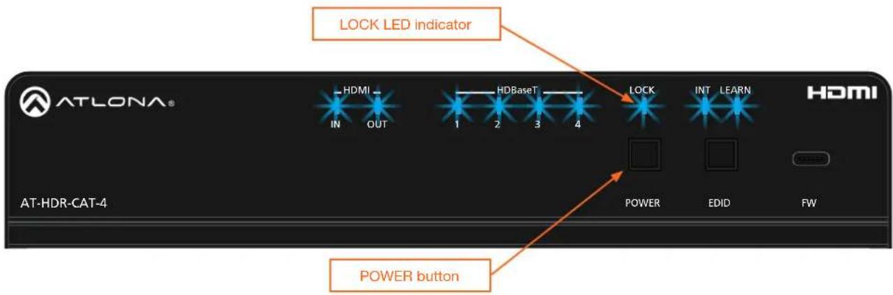
text_image
LOCK LED indicator HDMI IN OUT HDBaseT 1 2 3 4 LOCK INT LEARN HDMI POWER button POWER AT-HDR-CAT-4 EDID FW| POWER button flashes Description | ||
| Two Static IP mode IP address: | 192.168.1.254 | Netmask: 255.255.0.0Gateway: 192.168.1.1 |
| Four DHCP mode | ||
Using the Web Server
The IP mode of the AT-HDR-CAT-4 can also be set using the built-in web server. In order to access the web server, the IP address of the AT-HDR-CAT-4 must be known. Refer to Logging in to the Web Server (page 16) for more information.
- Open the desired web browser and enter the IP address of the AT-HDR-CAT-4.
- Log in using the required credentials.
- Click System in the menu bar.
-
Click the Save button to save the changes.
-
Click the IP Mode toggle to switch between the DHCP and STATIC IP setting. When set to STATIC IP, the IP, Netmask, and Gateway fields can be modified.

text_image
MAC Address: B8-98-B0-06-07-09 IP Mode: STATIC IP IP: 10.20.20.37 Netmask: 255.255.255.0 Gateway: 10.20.20.1 SaveSetting the IP Address Using Commands
Use the IPStatic and IPDHCP commands to switch between DHCP and IP mode through RS-232 or Telnet. Refer to API documentation for more information. All commands and their arguments are case-sensitive.

IMPORTANT: Note that when switching between DHCP and static modes, within a Telnet session, the connection will be terminated once the IPDHCP command is executed.
- Setting static IP mode
- Connect to the AT-HDR-CAT-4 using RS-232 or Telnet.
- Execute the IPStatic command. This command requires three arguments: the desired IP address of the AT-HDR-CAT-4, the subnet mask, and the gateway address. All arguments must be entered in dot-decimal notation. The following is an example:
IPStatic 192.168.1.112 255.255.255.0 192.168.1.1 IP address Subnet mask Gateway
- Setting DHCP mode
-
Connect to the AT-HDR-CAT-4 using RS-232 or Telnet.
-
At the command line, execute the IPDHCP command using the on argument, as shown. All characters are case-sensitive.
IPDHCP on
Once DHCP is enabled, the unit will be assigned an IP address by the DHCP server (if present).
Auto IP (APIPA) Mode
If the AT-HDR-CAT-4 is unable to detect a DHCP server within 15 seconds, when set to DHCP mode, then the unit will use a self-assigned IP address within the IPv4 address block 169.254.xxx.xxx/16. If this occurs, connect an Ethernet cable directly from the LAN port of the AT-HDR-CAT-4 to the LAN port of a computer, then do the following:
- Click Start > Settings > Control Panel > Network and Sharing Center.
- Click Change adapter settings.
- Right-click on the adapter that is used to establish a wired connection to the network, and select Properties from the context menu.
- Under the Ethernet Properties dialog box, select Internet Protocol Version 4 and then click the Properties button. Click the Use the following IP address radio button.

IMPORTANT: Before continuing, write down the current IP settings in order to restore them, later. If Obtain an IP address automatically and Obtain DNS server automatically are selected, then this step is not required.
-
Enter the desired static IP address or the IP address provided by the network administrator. If the computer does not require Internet access or if a statically-assigned IP address is being used, then an address within the IPv4 address block 169.254.xxx.xxx/16 can be entered.
-
Set the subnet mask to 255.255.0.0.
-
Click the OK button then close all Control Panel windows.
Device Operation
LED Indicators
The LED indicators on both the front of the unit provide basic information on the current status of the AT-HDR-CAT-4.
| LED Description | ||
| POWER Blue | Unit is powered and in normal operating mode. | |
| Red Unit is in standby mode. | ||
| Off Unit is not powered. | Press the POWER button to place the unit in normal operating mode. | |
| Check the power supply and make sure it is securely fastened to the locking connector on the rear of the unit. | ||
| Make sure that the power supply is connected to an available electrical outlet and that the outlet is “live” (some outlets are controlled by a wall switch). | ||
| HDMI IN / OUT | Blue IN: Source is connected to the HDMI IN port. | |
| OUT: Sink device is connected to the HDMI OUT port. | ||
| Off IN: No source device connected to the HDMI IN port. | ||
| OUT: No sink device is connected to the HDMI OUT port. | ||
| Check the integrity of the HDMI cable; make sure a secure connection exists between the HDMI port on the AT-HDR-CAT-4 and the source/ display device. | ||
| Try a different HDMI cable. | ||
| HDBaseT 1/2 | Blue Normal operation. Signal integrity between the AT-HDR-CAT-4 and the connected receiver is good. Note that when connected to an HDBaseT receiver, with an active sink, the LED indicator will be blue. If no active sink is connected, or the sink is powered off, then the indicator will not be illuminated. | |
| Off No connection between the HDBaseT port on the AT-HDR-CAT-4 and the receiver unit. | ||
| Check the category cable for a secure connection. | ||
| Possible bad cable; try a different category cable. | ||
| LOCK Blue Front-panel buttons on the AT-HDR-CAT-4 are locked. Refer to the API or Locking / Unlocking the Front Panel (page 18) for more information. | ||
| INT Blue AT-HDR-CAT-4 is using the internal EDID. Refer to EDID Management (page 19) for more information on INT EDID mode. | ||
| LEARN Blue AT-HDR-CAT-4 is in “learn” mode. Refer to EDID Management (page 19) for more information on LEARN EDID mode. | ||
Logging in to the Web Server
Most of the AT-HDR-CAT-4 operation is handled through the built-in web server. In order to access the web server, the IP address of the unit must be known. Refer to IP Configuration (page 12) for more information.
Login Registration
Before the built-in web server can be accessed, a username and password must be created.
- Launch the desired web browser and enter the IP address of the AT-HDR-CAT-4 in the address bar.
- The AT-HDR-CAT-4 Register page will be displayed.

text_image
ATLONA e-Door company AT-HDR-CAT-4 Register Register Username admin Password .......... Confirm .......... ... Submit Register Username admin Password .......... Confirm .......... ...... Submit- Enter the desired username in the Username field. In the example above, the username admin is used.
- Enter the desired password in the Password field.

IMPORTANT: The password must contain a minimum of 8 characters, including: 1 uppercase character, 1 lowercase character, and 1 number. Special characters are not permitted. Note that the Password and Confirm fields will be masked when entering the password.
- Verify the password by entering it in the Confirm field.
- Click the Submit button.
- The Login screen will be displayed.
- The login registration process is complete.
Device Operation
Logging in after Registration
- Launch the desired web browser and enter the IP address of the AT-HDR-CAT-4 in the address bar.
- Enter the correct username and password in the respective fields.
- Click the Submit button.

text_image
Login Username admin Password .......... Submit- The Info page will be displayed and the login process is complete. Refer to Info page (page 40) for more information.
Locking / Unlocking the Front Panel
The buttons on the front panel can be locked or unlocked. Locking the front-panel buttons prevents accidental pressing of the buttons, which may occur when the unit is mounted in a rack environment. Locking and unlocking of the front-panel buttons is managed through the web server or by executing the Lock and Unlock API commands. Refer to the API documentation for more information.

NOTE: Locking the front-panel buttons will also lock the EDID, preventing the EDID mode from being switched between INT and LEARN modes.
Using the Front Panel
- Make sure the unit is powered.
-
Press and hold the POWER button for five seconds.
-
Release the POWER button. The LOCK LED indicator on the front panel will glow solid blue. The front panel buttons are now locked.
-
To unlock the front-panel buttons, press and hold the POWER button for five seconds, then release. The LOCK LED indicator will no longer be illuminated.

text_image
ATLONA® HDMI IN OUT 1 2 3 4 HDBaseT LOCK INT LEARN LOCK LED indicator HDMI POWER button POWER FAT-DIDUsing the Web Server
- Log in to the web server.
- Click System in the menu bar.
- Locate the System section and click the Lock toggle button to switch between LOCK and UNLOCK states.

text_image
System Power ON Lock LOCK Power button mode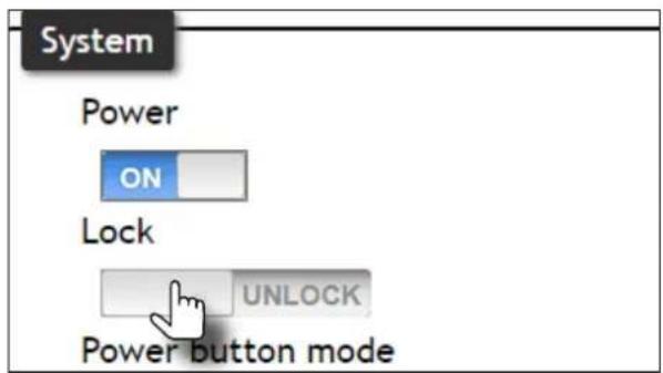
text_image
System Power ON Lock UNLOCK Power button mode- The LOCK LED indicator, on the front panel, will reflect the current state. When the front-panel buttons are locked, the LOCK LED indicator will glow solid blue.
EDID Management
The AT-HDR-CAT-4 provides two EDID modes: INT and LEARN. The default EDID mode is INT mode. In this mode, the AT-HDR-CAT-4 will automatically create an EDID based on the capabilities of all connected displays. INT mode is recommended for the best results when the capabilities of all connected displays are unknown. INT mode can also be used to select any of 9 EDID presets. Refer to Selecting EDID Presets (page 21) for more information on this topic. LEARN mode can be used to capture an EDID from any sink device. Once the EDID is learned, it will be used by the connected source device to determine what video and audio formats can be sent to the sink device.
Learning an EDID using the Front Panel

IMPORTANT: In order for EDID learning to take place, a display must be connected to HDBaseT OUT 1.
- Power the AT-HDR-CAT-4.
-
Connect a category cable from the HDBaseT OUT 1 port on the AT-HDR-CAT-4 to a receiver (e.g. AT-HDR-EX-70C-RX).
-
Connect an HDMI cable from the receiver to the display (sink) device. Make sure that the sink device is powered.

flowchart
graph TD
    A["AT-HDR-CAT-4"] -->|HDIS port (VIT 1)| B["AT-HDR-EX-70C-RX"]
    B -->|HDMI| C["Display"]
- Press and hold the EDID button on the AT-HDR-CAT-4. Release the EDID button once the LEARN LED indicator begins to flash rapidly.
text_image
EDID button ATLONA® HDMI IN OUT 1 2 3 4 HDBaset LOCK INT LEARN AT-HDR-CAT-4 POWER FWEDIDOnce the EDID is learned, it will be used by the connected source device to determine what video and audio formats can be sent to the sink device(s). To switch back to INT mode, quickly press and release the EDID button.

NOTE: If the AT-HDR-CAT-4 is accidentally switched to INT mode, quickly press and release the EDID button to switch back to LEARN mode. Switching back and forth between INT and LEARN mode will not erase the "learned" EDID. In addition, switching to LEARN mode cannot be performed if an EDID has not been learned.
Learning the EDID using the Web Server
- Follow steps 1 through 3 under Learning an EDID using the Front Panel (page 19).
- Log in to the web server.
- Click EDID in the menu bar.

text_image
EDID EDID lock UNLOCK EDID mode INT INT EDID settings INT LEARN COPY EDID copy- Click the EDID mode drop-down list and select LEARN.
- Click the COPY button to copy the downstream EDID to memory.
The AT-HDR-CAT-4 will now use the EDID of the downstream sink. To switch back to the INT mode, click the EDID mode drop-down list and select INT.

NOTE: The COPY button will be disabled if there is no display connected to HDBaseT OUT 1.
Locking the EDID
To prevent accidental switching between INT and LEARN modes, the EDID can be locked.

NOTE: Locking the EDID will also lock all front-panel buttons.
- Log in to the web server.
- Click EDID in the menu bar.
- Click the EDID lock toggle button to switch between LOCK and UNLOCK states.

text_image
EDID EDID lock EDID mode INT INT EDID settings Connected Display EDID copy UNLOCK COPY
text_image
EDID EDID lock EDID mode INT EDID settings EDID copy LOCK INT Connected Display COPY- The LOCK LED indicator, on the front panel, will reflect the current state. When the EDID is locked, the LOCK LED indicator will glow solid blue. This also serves to indicate that all front-panel buttons are locked.
Device Operation
Selecting EDID Presets
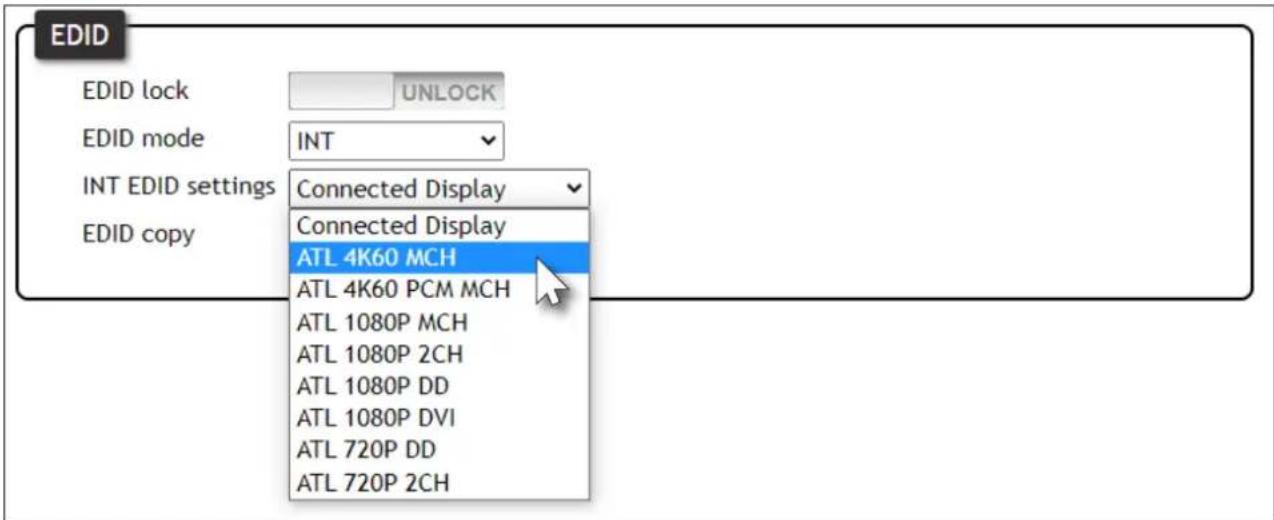
The AT-HDR-CAT-4 comes with a default EDID plus 8 pre-programmed EDID selections. When selecting the default or one of the pre-programmed EDID selections, the EDID mode must be set to INT (internal) mode.
Available EDID selections are presented in the table below. All resolutions are 60 Hz.
| EDID Description | |
| Connected Display Uses the downstream | EDID of the connected display |
| ATL 4K60 MCH 3840 x 2160 (UHD) with multichannel audio support | |
| ATL 4K60 PCM MCH 3840 x 2160 (UHD) with PCM multichannel audio support | |
| ATL 1080P MCH 1920 x 1080p with multichannel audio support | |
| ATL 1080P 2CH 1920 x 1080p with two-channel audio support | |
| ATL 1080P DD 1920 x 1080p with Dolby | TM Digital audio support |
| ATL 1080P DVI 1920 x 1080p for DVI displays | |
| ATL 720P DD 1280 x 720p with Dolby | TM Digital audio support |
| ATL 720P 2CH 1280 x 720p with two-channel audio support | |

NOTE: If the resolution and timing limitations of both displays, connected to the HDBaseT OUT port, are unknown, then select the Connected Display EDID for the best compatibility.
The Connected Display EDID will automatically build an EDID based on the capabilities of both displays. When selecting an EDID, make sure both connected displays can support the resolution and timing information. Otherwise, loss of picture and/or audio may result.
- Log in to the web server.
- Click EDID in the menu bar.
- Make sure the EDID lock toggle switch is set to UNLOCK.
-
Click the EDID mode drop-down list and select INT.
-
Select the desired EDID from the INT EDID settings drop-down list. The selected EDID will be used by the source, before sending A/V data to the display (sink) device.
text_image
EDID EDID lock UNLOCK EDID mode INT INT EDID settings Connected Display Connected Display ATL 4K60 MCH ATL 4K60 PCM MCH ATL 1080P MCH ATL 1080P 2CH ATL 1080P DD ATL 1080P DVI ATL 720P DD ATL 720P 2CHChanging Login Credentials
The AT-HDR-CAT-4 allows both the username and password to be changed. These credentials apply to both the built-in web server and Telnet sessions.

NOTE: When creating passwords, special characters are not supported. Password fields will always be masked for security purposes.
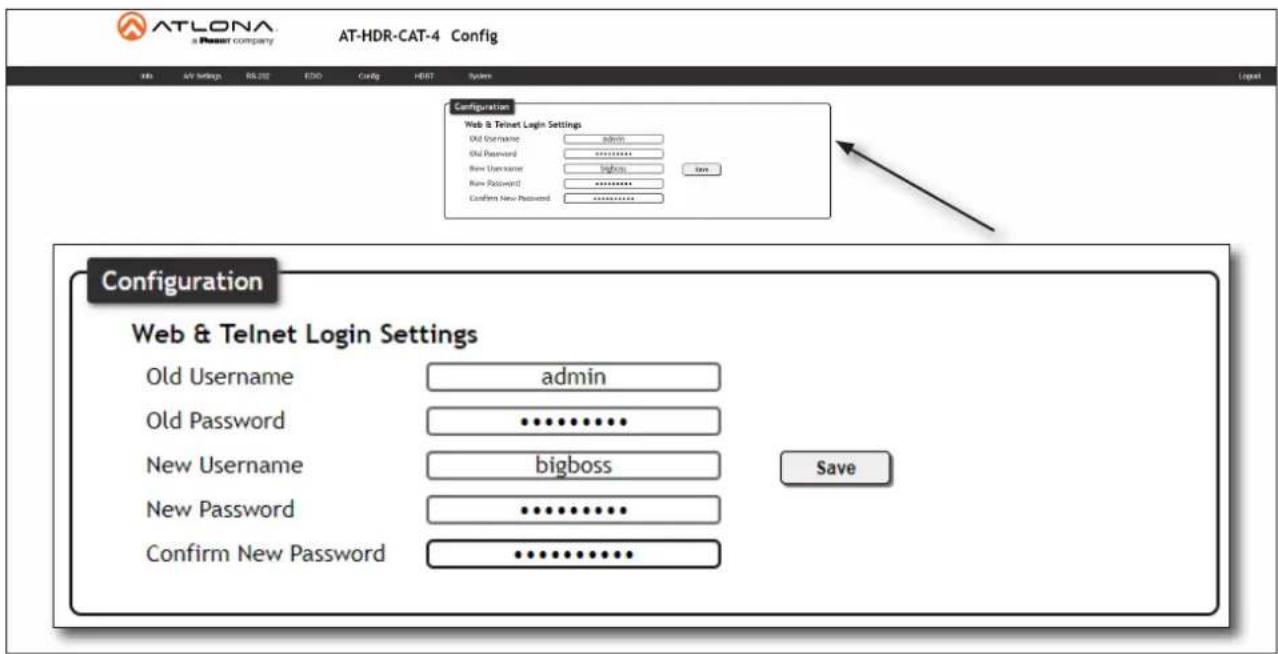
Changing the Username and Password
- Log in to the web server.
- Click Config in the menu bar.
- Click the Old Username field and enter the current username.
text_image
ATLONA x Resort Company AT-HDR-CAT-4 Config Web 5V Settings RS 202 E50 Config H8E7 System Configuration Web & Telnet Login Settings Old Username admin Old Password ********** New Username passwords Save New Password ********** Confirm New Password ********** Configuration Web & Telnet Login Settings Old Username admin Old Password ********** New Username bigboss Save New Password ********** Confirm New Password ********...- Enter the current password in the Old Password field.
- Enter the new username in the New Username field.
- Enter the new password in the New Password field.
- Retype the new password in the Confirm New Password field.
- Click the Save button to commit changes. To log in with the new username, click Logout in the upper-right corner of the screen, then enter the new password on the Login page.
Controlling Audio Output
The AT-HDR-CAT-4 features a separate AUDIO OUT port on the rear panel. This port provides de-embedding and conversion of two-channel LPCM audio streams to analog audio. Audio output volume can be controlled using API commands or the built-in web server.

IMPORTANT: The AT-HDR-CAT-4 will only de-embed two-channel LPCM audio. Down-mixing multichannel audio to two-channel audio is not supported. In addition, video must accompany the audio at all times. This product does not support audio-only ("free-run" mode) output.
Audio Port Wiring
The included 5-pin captive screw block can be wired to support balanced audio using XLR connectors, or unbalanced audio using RCA connectors.
Balanced Audio (XLR)
| Channel Signal (AT-HDR-CAT-4) Pin (XLR) | ||
| R - 3 | ||
| R + 2 | ||
| -- GND* 1 | ||
| L + 2 | ||
| L - 3 | ||
*The GND signal, from the 5-pin captive screw connector on the AT-HDR-CAT-4, should be tied to pin 1 on both XLR connectors.

natural_image
Green electrical connector with three black leads and red lines, no text or symbols visibleUnbalanced Audio (RCA)
| Channel Signal (AT-HDR-CAT-4) Pin (RCA) | ||
| R to GND* -- | ||
| R++ | ||
| -- GND GND | ||
| L++ | ||
| L to GND* -- | ||
*The GND signal, from the captive screw connector on the AT-HDR-CAT-4, should be tied to L- and R- on the captive screw connector.

natural_image
Green terminal block with three leads and three red lines, connected to black and red wires (no text or symbols)Device Operation
De-Embedding Audio
- Log in to the web server.
- Click A/V Settings in the menu bar.
- Click Analog Output toggle switch and set to the ON position. To mute the audio output on the AUDIO OUT port, click this toggle switch to the OFF position.

text_image
Settings HDCP Compliant Analog Output ON Analog Audio Output Volume 0 -Adjusting the Volume Level
- Log in to the web server.
- Click A/V Settings in the menu bar.
- Click and drag the Analog Audio Output Volume slider to the right to increase the output level. Drag the slider to the left to decrease the output level.

text_image
Settings HDCP Compliant Analog Output ON Analog Audio Output Volume 0 - +RS-232 Control
The AT-HDR-CAT-4 provides two methods of RS-232 control: Pass-through mode and control mode. The MASTER RS-232 / IR port, allows the unit to be directly controlled using a control system. In addition four pass-through RS-232 / IR ports allow sink devices, at the viewing location, to be controlled using a control system.
RS-232 is serial data protocol that allows Data Terminal Equipment (DTE) devices, such a computer or control system, to communicate with Data Communication Equipment (DCE) devices, such as the AT-HDR-CAT-4 or a display. Although IP control is available, RS-232 still plays an integral part of many control systems. The 25-pin D-type connector (DB-25) was defined as the RS-232 standard, but is now commonly implemented in a nine-pin (DE-9) connector package. Each pin is numbered, as shown below.
DE-9 (male) DE-9 (female)

text_image
12345 6789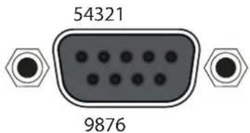
text_image
54321 9876DTE Pin Descriptions
| Pin Signal Description | ||
| 1 | DCD | Data Carrier Detect |
| 2 | RxD | Receive Data |
| 3 | TxD | Transmit Data |
| 4 | DTR | Data Terminal Ready |
| 5 | GND | Ground (Signal) |
| 6 | DSR | Data Set Ready |
| 7 | RTS | Request to Send |
| 8 | CTS | Clear to Send |
| 9 | RI Ring Indicator | |
DCE Pin Descriptions
| Pin Signal Description | ||
| 1 | DCD | Data Carrier Detect |
| 2 | TxD | Transmit Data |
| 3 | RxD | Receive Data |
| 4 | DSR | Data Set Ready |
| 5 | GND | Ground (Signal) |
| 6 | DTR | Data Terminal Ready |
| 7 | CTS | Clear to Send |
| 8 | RTS | Ready to Send |
| 9 | RI Ring Indicator | |
RS-232 Port Wiring
When connecting a DTE device to a DCE device, a straight-through cable should be used. A straight-through cable is wired in such a way that the pins on one side of the cable are connected to the corresponding pins on the opposite side of the cable, as shown in the table below. However, the AT-HDR-CAT-4 will use only TxD, RxD, and GND signals when communicating with a control system or computer. Refer to connection instructions on the next page.
Straight-Through Cable
| Pin | Signal | Signal Pin | ||
| 1 | DCD | DCD 1 | ||
| 2 | RxD | TxD 2 | ||
| 3 | TxD | RxD 3 | ||
| 4 | DTR | DSR 4 | ||
| 5 | GND | GND 5 | ||
| 6 | DSR | DTR 6 | ||
| 7 | RTS | CTS | 7 | |
| 8 | CTS | RTS | 8 | |
| 9 | RI | RI 9 |
Device Operation
- Identify the DE-9 connector that will be attached to the control system or computer (DCE) equipment.
- Remove the DE-9 connector at the opposite end of the cable with wire cutters.
- Remove at least 1" of the cable insulation to expose each of the nine wires.
- Locate a multimeter and set it to the "continuity" function.
- Attach one of the leads from the multimeter to pin 2 on the DE-9 connector.
- Take the other lead and probe each of the wires on the opposite end of the cable. When the wire connected to that pin is detected, the multimeter will emit an audible tone. Once this occurs, identify the current wire, and move it to the side.
- Repeat step 6 for pin 3 and pin 5 on the DE-9 connector.
- Group the remaining wires and pull them aside. Electrical tape can be use to secure the wires to the outside of the RS-232 cable.
- Remove at least 3/16" (5 mm) of insulation from the TxD, RxD, and GND wires.

text_image
IRRS-232 RX TX RXTX LAN
natural_image
Green electrical connector with three pins, connected to labeled terminals (GND, TXD, RXD) without any text or symbols on the component itself.- Locate the included 5-pin captive screw block and open each of the terminals by turning the screws counter-clockwise, using a small regular screwdriver.
- Insert the TxD, RxD, and GND wires into correct terminal, as shown, and tighten the screws to secure each wire. Do not overtighten.
Device Operation
Pass-through mode
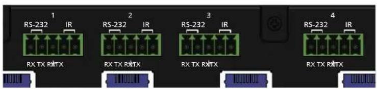
In pass-through mode, RS-232 commands are passed-through the AT-HDR-CAT-4, transmitted over HDBaseT to a receiver unit, and then to the display (sink) device. Note that each RS-232 / IR port is assigned to an HDBaseT OUT port. This assignment is fixed and cannot be changed, as shown in the table below.
| RS-232 / IR Port HDBaseT Port | |
| RS-232 / IR 1 HDBaseT OUT 1 | |
| RS-232 / IR 2 HDBaseT OUT 2 | |
| RS-232 / IR 3 HDBaseT OUT 3 | |
| RS-232 / IR 4 HDBaseT OUT 4 |
- Connect the RS-232 cable from the control system to the desired RS-232 / IR port on the AT-HDR-CAT-4. Refer to RS-232 Port Wiring (page 25) for instructions on preparing the cable.
- Connect a category cable from the desired HDBaseT OUT port to a receiver. In this example, the HDBaseT cable is connected from HDBaseT OUT 2 to a compatible receiver (the RS-232 cable is connected from the control system to the RS-232 / IR 2 port).
- Connect an RS-232 cable between the display (sink) and the receiver.
- Adjust the RS-232 settings on the control system to match the requirements of the sink device. For example, if the RS-232 settings for the display device are 9600, N, 8, 1, then set the control system to the same settings. If the control system and sink device settings do not match, then RS-232 control will not function.
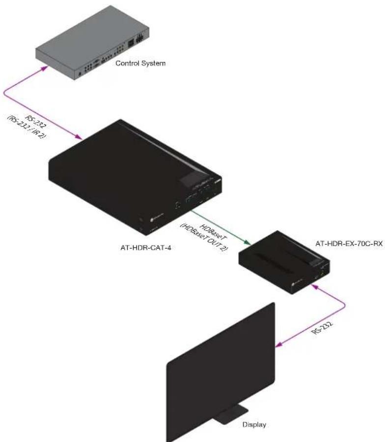
flowchart
graph TD
    A["Control System"] -->|RS-232 (RS-231/IR-2)| B["AT-HDR-CAT-4"]
    B -->|HDBset (HDBset Out-2)| C["AT-HDR-EX-70C-RX"]
    C -->|RS-22| D["Display"]
Device Operation
Control mode
In control mode, the MASTER RS-232 / IR port is used to directly control the AT-HDR-CAT-4 using a control system.
- Launch a web browser and log in to the web server.
- Connect the RS-232 cable between the control system and the MASTER RS-232 / IR port on the AT-HDR-CAT-4. Refer to RS-232 Port Wiring (page 25) for instructions on preparing the cable.

flowchart
graph LR
    A["Control System"] -->|RS-232| B["Device"]
AT-HDR-CAT-4
- Click RS-232 in the menu bar.
- Select the proper baud rate, data bit, parity, and stop bit settings. These settings must correspond with the control system RS-232 settings.
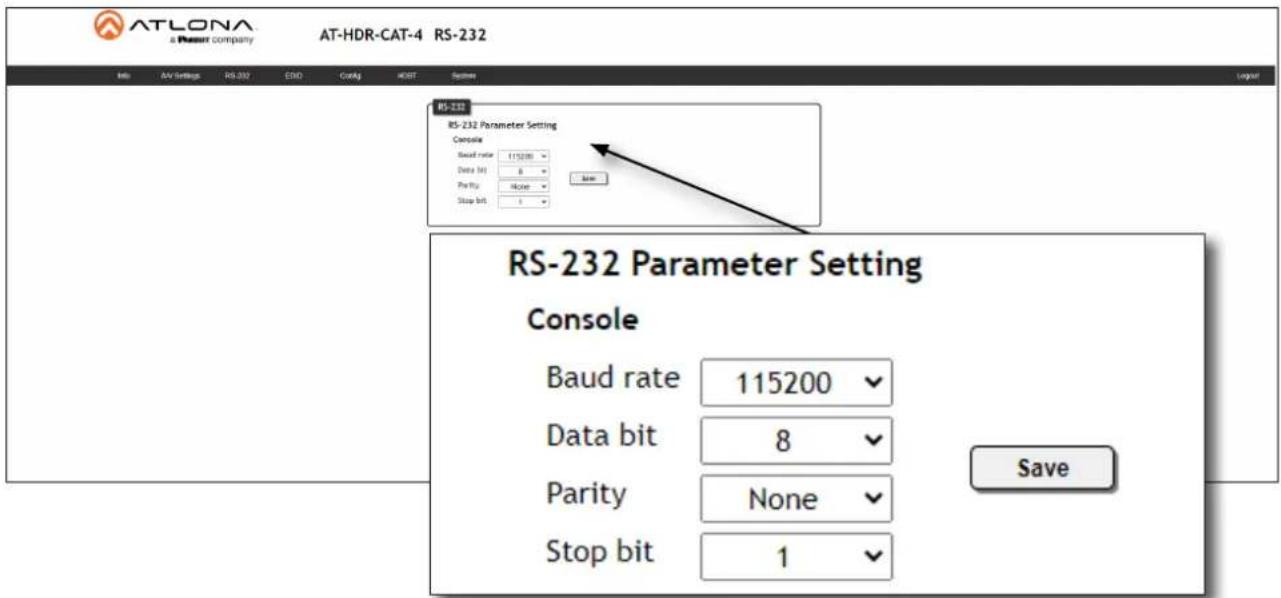
text_image
ATLONA a Plesur company AT-HDR-CAT-4 RS-232 File Edit Settings RS-232 END Config HIST System RS-232 RS-232 Parameter Setting Console Baud rate 115200 Data bit 8 Parity None Stop bit 1 RS-232 Parameter Setting Console Baud rate 115200 Data bit 8 Parity None Stop bit 1 Save RS-232 Parameter Setting Console Baud rate 115200 Data bit 8 Parity None Stop bit 1- Click the Save button to commit changes.
IR Control
IR can be used to control either source devices at the headend or devices connected to the receiver endpoint, such as a display. Note that the MASTER RS-232 / IR port does not support IR control. Each RS-232 / IR port is assigned to an HDBaseT OUT port. This assignment is fixed and cannot be changed, as shown in the table below. IR is compatible with frequencies from 30 kHz to 60 kHz.
| RS-232 / IR Port HDBaseT Port | |
| RS-232 / IR 1 HDBaseT OUT 1 | |
| RS-232 / IR 2 HDBaseT OUT 2 | |
| RS-232 / IR 3 HDBaseT OUT 3 | |
| RS-232 / IR 4 HDBaseT OUT 4 |
Controlling Display Devices
- Remove at least 3/16" (5 mm) of insulation from the TX and GND wires.
- Locate the included 5-pin captive screw block and open each of the terminals by turning the screws counterclockwise, using a small regular screwdriver.
- Insert the TX and GND wires into correct terminal, as shown, and tighten the screws to secure each wire. Do not overtighten.
- Connect the captive screw connector to the RS-232 / IR IN port of the zone to be controlled.
- Connect the RX terminal, from the AT-HDR-CAT-4, to the TX terminal on the control system.
- Connect the GND terminal, from the AT-HDR-CAT-4, to the GND terminal on the control system.
text_image
1 RS-232 IR 2 RS-232 IR RS-232 IR 3 RS-232 IR 4 RS-232 IR RX TX RMTX RX TX RMTX RX TX RMTX RX TX RMTX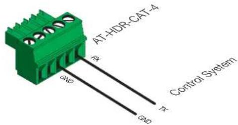
text_image
AT-HDR-CAT-4 PA GND Control System PA GND- Connect the IR emitter to the receiver and place the emitter next to the display (sink) device, as shown in the illustrator below.

flowchart
graph TD
    A["Control System"] -->|IR| B["AT-HDR-CAT-4"]
    B -->|IR Signal| C["AT-HDR-EX-70C-RX"]
    C -->|IR Signal| D["Display"]
    C -->|IR Emitter| E["Output"]
Device Operation
Controlling Source Devices
- Remove at least 3/16" (5 mm) of insulation from the RX and GND wires of the emitter.
- Locate the included 5-pin captive screw block and open each of the terminals by turning the screws counterclockwise, using a small regular screwdriver.
- Insert the S (signal) lead of the IR emitter to the TX terminal on the AT-HDR-CAT-4 captive screw connector. Tighten the screw to secure the wire but do not overtighten.
- Insert the GND lead of the IR emitter to the GND terminal on the AT-HDR-CAT-4 captive screw connector. Tighten the screw to secure the wire but do not overtighten.
- Connect the captive screw connector to the RS-232 / IR IN port of the zone to be controlled.

text_image
1 RS-232 IR 2 RS-232 IR RS-232 IR RS-232 IR RS-232 IR RX TX TX RX RX TX TX RX RX TX TX RX RX TX TX RX 4 RS-232 IR
text_image
AT-HDR-CAT-4 GND P S GND IR Emitter- Place the IR emitter next to the source device, as shown in the illustration below.

flowchart
graph LR
    A["Blu-ray Player"] -->|IR Signal| B["AT-HDR-CAT-4"]
    B -->|IR Receiver| C["AT-HDR-EX-70C-RX"]
    C -->|IR Signal| D["Blu-ray Player IR Remote"]
    B -->|IR Emitter (RS-232/IR 1)| B
    B -->|HDBsetT (HDBsetT OUT 1)| C
Power Button Modes
The main function of the POWER button on the front panel is to toggle the AT-HDR-CAT-4 between standby and normal operating mode. This is the default mode. However, this button can also be defined to send CEC power-on and power-off commands, over HDBaseT, to the display (sink) devices. It can also be defined to simultaneously power-on or power-off the AT-HDR-CAT-4 and any connected displays.
Normal Operation
By default, pressing the POWER button will toggle the power state of the AT-HDR-CAT-4. When the unit is in normal operating mode, the POWER button will be blue. Pressing the POWER button again, will place the unit into standby mode, and the POWER button will be red. In standby mode, no video signal will pass to the display (sink) device. However, TCP/IP access to the unit will be maintained, allowing access to the web server and Telnet sessions.
- Launch a web browser and log in to the web server.
- Click System in the menu bar.
- Click the Power button mode drop-down list and select DA standby. Pressing the POWER button on the front panel will toggle between power-on and standby modes on the AT-HDR-CAT-4. Connected display (sink) devices will not receive CEC power-on / power-off messages.
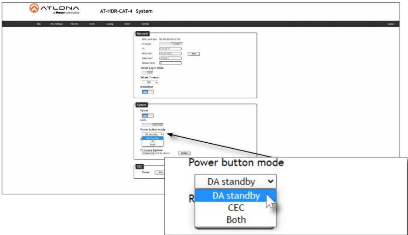
text_image
ATLONA a Pheasant company AT-HDR-CAT-4 System Info AV Settings RS-202 ESD Config HODT System Network MRC, admin: 86.96.89-06-07 09 IP Mode: 10000 IP: 5.000.00 Network: 5.000.00 Gateway: 5.000.00 Signal Port: 0 Telnet Login Mode TCP Telnet Timeout 120 Broadcast System Power Lock UNKNOWN Power button mode BA standby BA standby CEC Both Firmware Update Charge File No file chosen Enable Power button mode DA standby DA standby CEC BothDevice Operation
Controlling Power on Sink Devices
This section provides information on how to power-on / power-off the display (sink) device, using the POWER button. CEC* power-on / power-off commands are transmitted over both HDBaseT OUT ports, as well as the pass-through HDMI OUT port.
- Connect category cables from the HDBaseT OUT ports to receiver (e.g. AT-HDR-EX-70C-RX).
- Connect an HDMI cable from the receiver to the display (sink) device. Make sure that the sink device is powered.

flowchart
graph LR
    A["AT-HDR-CAT-4"] -->|HDBAeT OUT1| B["AT-HDR-EX-70C-RX"]
    B -->|HDMI| C["Display"]
-
Launch a web browser and log in to the web server.
-
Click System in the menu bar.
-
Click the Power button mode drop-down list and select CEC. Refer to the illustration on the next page.
*Consumer Electronics Control (CEC): Atlona has confirmed proper CEC functionality with several current models of Samsung, Panasonic, and Sony displays. However, it is not guaranteed that CEC will work with all displays. Many manufacturers do not support the CEC "off" command, and older displays use proprietary commands. Atlona only supports displays that use the CEC command structure defined in HDMI 1.2a. It is recommended that dealers request an evaluation product from Atlona, before designing a system using the CEC protocol. If this is not possible, then other control methods will need to be considered, in order to control displays using Atlona products.
Device Operation

text_image
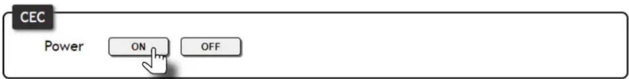
ATLONA a Passat company AT-HDR-CAT-4 System Info AV Linkage RB-032 EDD Care/G HDDT System Network MAC Address: 88.96.80.06.07.09 IP Mode: 100% SP: 100.00.00 Network: 100.00.00 Gateway: 100.00.00 Telnet Port: 1 Telnet Login Mode TCP Telnet Timersuit 120 Broadcast: Power Lock Power button mode BA standby BA standby Both Hardware Update Database Set: No to Drawn Index Power button mode DA standby DA standby CEC Both- Test the CEC power-on and power-off commands by clicking the ON and OFF buttons, near the bottom of the page.

text_image
CEC Power ON OFF- Press the POWER button on the front panel to power-on or power-off the display. Note that the power state of the AT-HDR-CAT-4 will be unaffected.
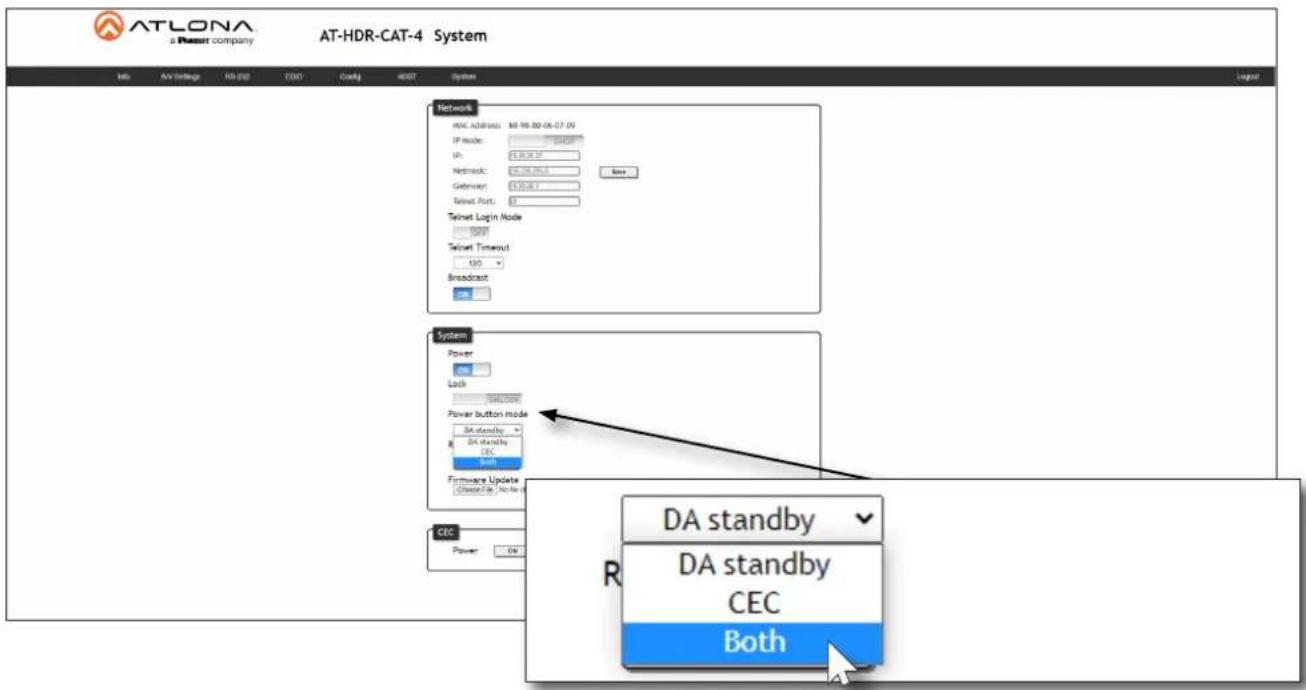
Controlling Power on Sinks and the AT-HDR-CAT-4
In this mode, the POWER button will power-on / power-off the unit and the connected displays. CEC* power-on / power-off commands are transmitted over both HDBaseT OUT ports.
- Make the proper connections by following steps 1 and 2, under Controlling Power on Sink Devices (page 32).
- Launch a web browser and log in to the web server. Refer to Introduction to the Web Server (page 29) for more information.
- Click the Power button mode drop-down list and select Both.
text_image
ATLONA a Press company AT-HDR-CAT-4 System Info AV https HD-230 ESD Csgg HDBT System Network MAC Address: 88.96.00-06-07.09 IP Node: 100000 Up: 5.00.00.00 Network: 5.00.00.00 Gateway: 5.00.00.00 Telnet Port: 5 Telnet Login Node TCP Telnet Timeout USB Broadcast: System Power Lock WIN.COM Power button mode DA standby DA standby CEC Both Firmware Update Citerate File: No file or CEC Power OK DA standby DA standby CEC Both- Test the CEC power-on and power-off commands for the display (sink) device by clicking the ON and OFF buttons, near the bottom of the page.
text_image
CEC Power ON OFF- Press the POWER button on the front panel to power-on or power-off both the display and AT-HDR-CAT-4.
*Consumer Electronics Control (CEC): Atlona has confirmed proper CEC functionality with several current models of Samsung, Panasonic, and Sony displays. However, it is not guaranteed that CEC will work with all displays. Many manufacturers do not support the CEC "off" command, and older displays use proprietary commands. Atlona only supports displays that use the CEC command structure defined in HDMI 1.2a. It is recommended that dealers request an evaluation product from Atlona, before designing a system using the CEC protocol. If this is not possible, then other control methods will need to be considered, in order to control displays using Atlona products.
Device Operation
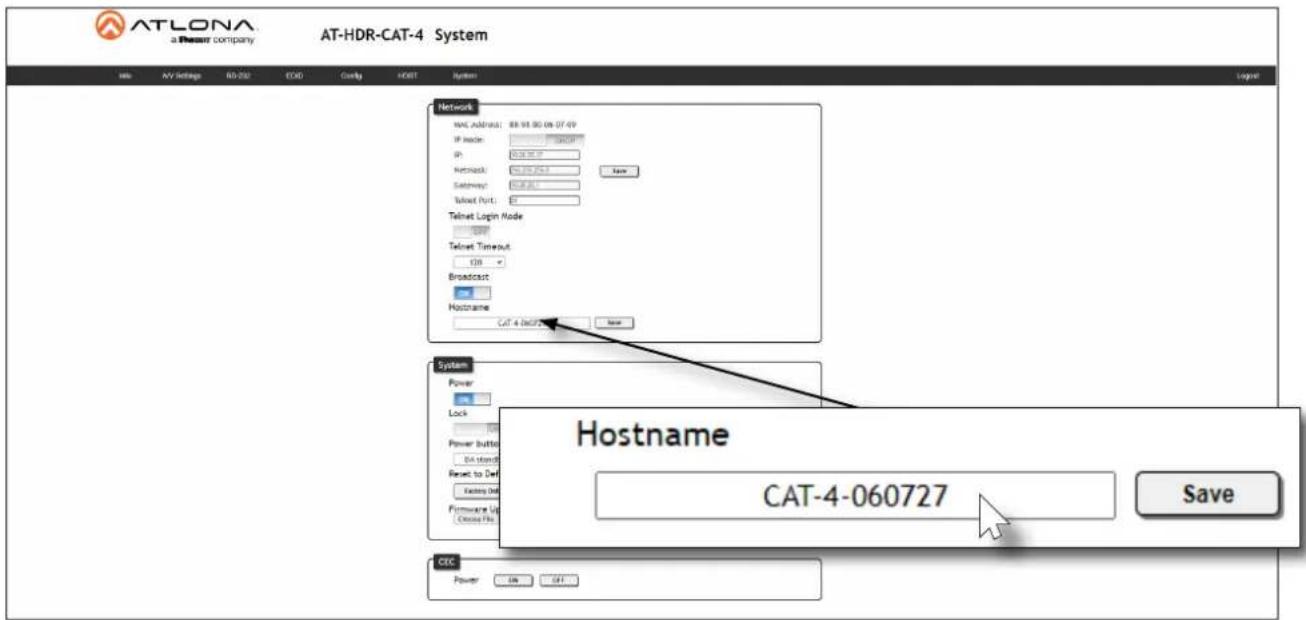
Setting the Host Name
By default, the AT-HDR-CAT-4 is assigned a hostname, which is constructed as follows:
CAT-4-[last six digits of MAC address]
For example, a default hostname might look like this: CAT-4-060709. This value can be changed to easily identify the AT-HDR-CAT-4 within the Velocity ^™ with Integrated AMS or a network. If using a custom hostname, it must meet the hostname standards, defined here: https://tools.ietf.org/html/rfc1123
- Launch a web browser and log in to the web server. Refer to Logging in to the Web Server (page 16).
- Click System in the menu bar.
- Click the Hostname field and enter the desired name.
- Click Save to commit changes.
text_image
ATLONA a Power company AT-HDR-CAT-4 System File AV Settings RD-230 ECD Config HDBT System Network WAC Address: 88.98.80 (07:49) IP Node: 1645P IP: 004567F Network: 004567E Sendray: 004567C Telnet Port: Telnet Login Mode: TCP Telnet Timeout: 120 Broadcast Hostname CAT-4-060727 Save System Power Lock Power Button: DA stand Reset to Def Existing Del Firmware Up Choose Pro Hostname CAT-4-060727 Save CEC Power On CATDevice Operation
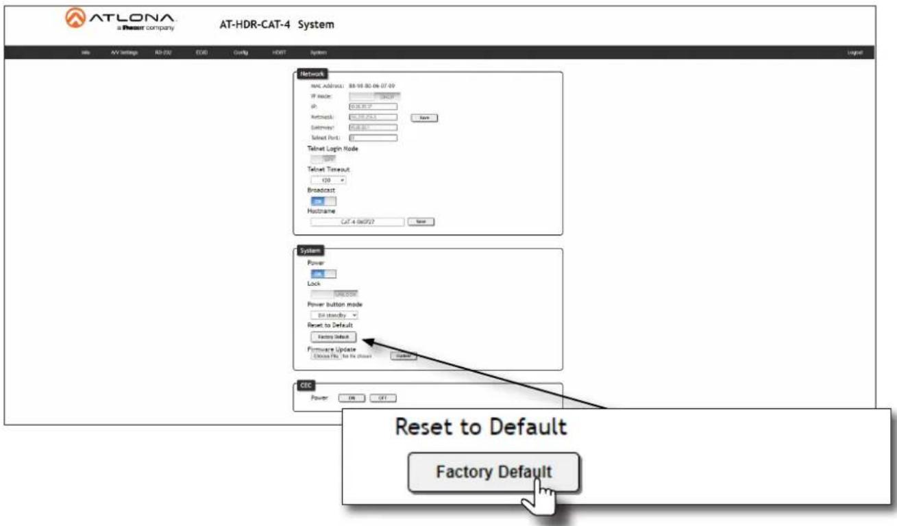
Resetting to Factory-Default Settings
The following procedure will reset the AT-HDR-CAT-4 to factory-default settings. The network IP mode will be set to DHCP mode.
Using the Web Server
- Launch a web browser and log in to the web server. Refer to Logging in to the Web Server (page 16).
- Click System in the menu bar.
- Click the Factory Default button.
text_image
ATLONA a Resour company AT-HDR-CAT-4 System File AV Settings RD-020 EDD Config HBDT System Network MAC Address: 88.98.80.06.07.09 IP Node: 100.00 IP: 100.00 Networks: 52.23.25.5 External: 100.00 Telnet Port: Telnet Login Node 100.00 Telnet Timeout: 120 Broadcast Hustrame CAT-4 0x02/23 New System Power Lock WIN,COM Power button mode En standby Reset to Default Factory Default Firmware Update Choose Files, En File (Choose) CEC Power ON OFF Reset to Default Factory Default- The following message will be displayed at the top of the screen. Click OK to continue with the factory-default reset procedure. Click Cancel to abort the process.
10.20.20.70 says
Are you Sure want to Reset Device to manufacture default?

- Once the factory-default process is complete, the web server Login screen will be displayed.
- The reset process is complete.
Device Operation
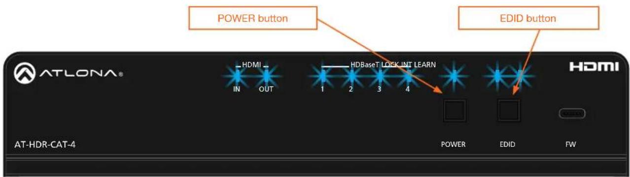
Using the Front Panel
- Press and hold both the POWER and EDID buttons for 15 seconds.
- Release both POWER and EDID buttons once the front panel LED indicators turn on. After two seconds, the front panel LED indicators will turn off.
text_image
POWER button EDID button AT-LONA® HDMI IN OUT 1 2 3 4 HDBaseT LOCK INIT LEARN HDMI POWER EDID FW AT-HDR-CAT-4Configuration and Management Interfaces
Web Server
The AT-HDR-CAT-4 includes a built-in web server. Atlona recommends that the web server be used to set up the AT-HDR-CAT-4, as it provides intuitive management of all features. Refer to Logging in to the Web Server (page 16) for more information.
The AT-HDR-CAT-4 is shipped with DHCP enabled. Once connected to a network, the DHCP server will automatically assign an IP address to the unit. Use an IP scanner to determine the IP address of the AT-HDR-CAT-4. If a DHCP server cannot be located within 15 seconds, the AT-HDR-CAT-4 will be placed in Auto IP (APIPA) Mode (page 14). If a static IP address is desired, refer to IP Configuration (page 12).
Register page
This page is displayed when the AT-HDR-CAT-4 web server is launched for the first time.

text_image
ATLONA a Power company AT-HDR-CAT-4 Register Register Username Username Password Password Confirm Password Submit Register Username Username Password Password Confirm Password SubmitUsername
Enter the desired username in this field.
Password
Enter the desired password in this field.
Confirm
Re-enter the desired password in this field.
Submit
Click this button to register the username and password with the AT-HDR-CAT-4.
Configuration and Management Interfaces
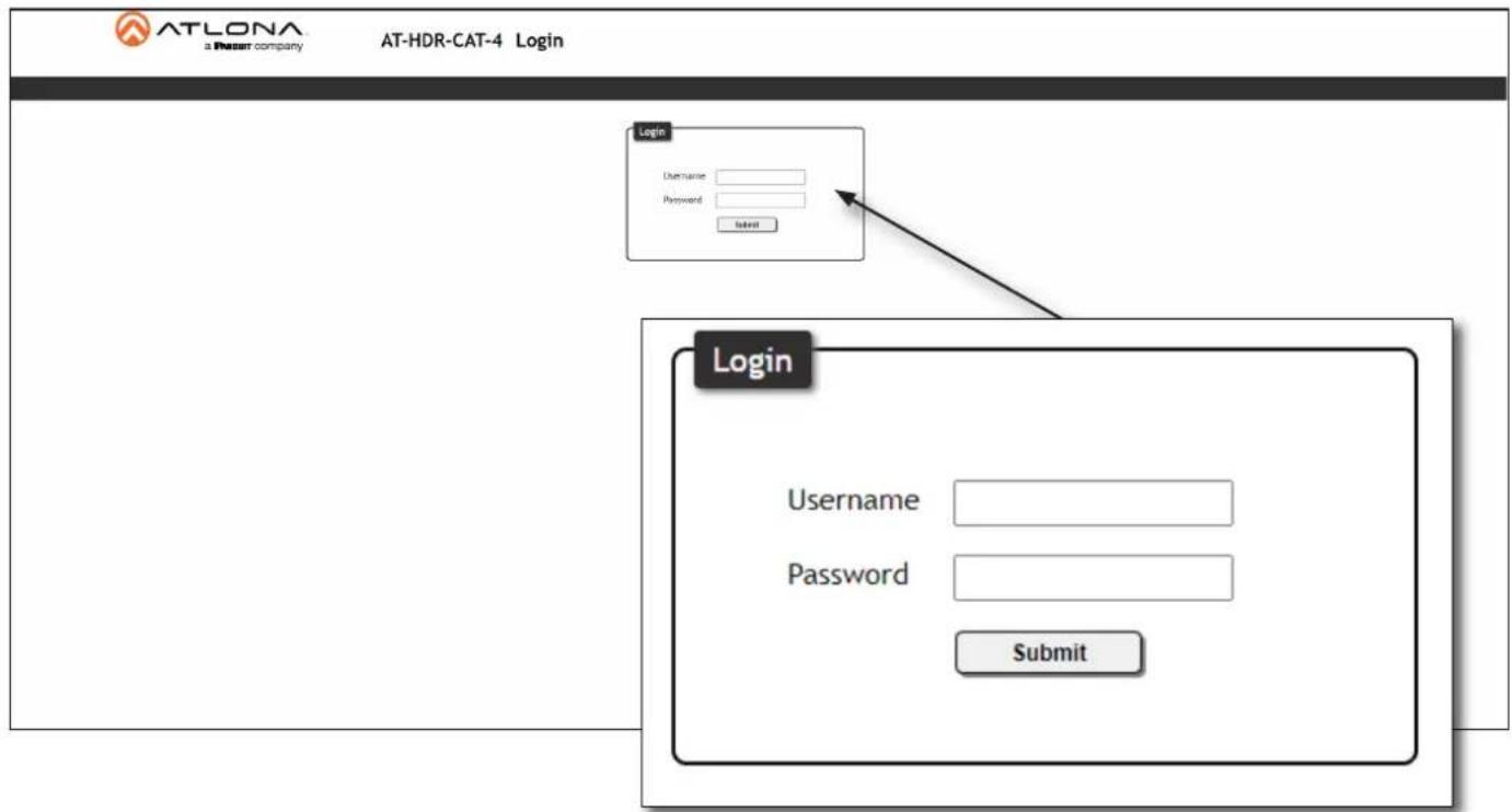
Login page
This page is displayed when the IP address of the AT-HDR-CAT-4 is entered in the address bar of a web browser.
text_image
ATLONA a Phezar company AT-HDR-CAT-4 Login Login Username Password Submit Login Username Password SubmitUsername
Enter the username in this field.
Password
Enter the password in this field.
Submit
Click this button to log in.
Configuration and Management Interfaces
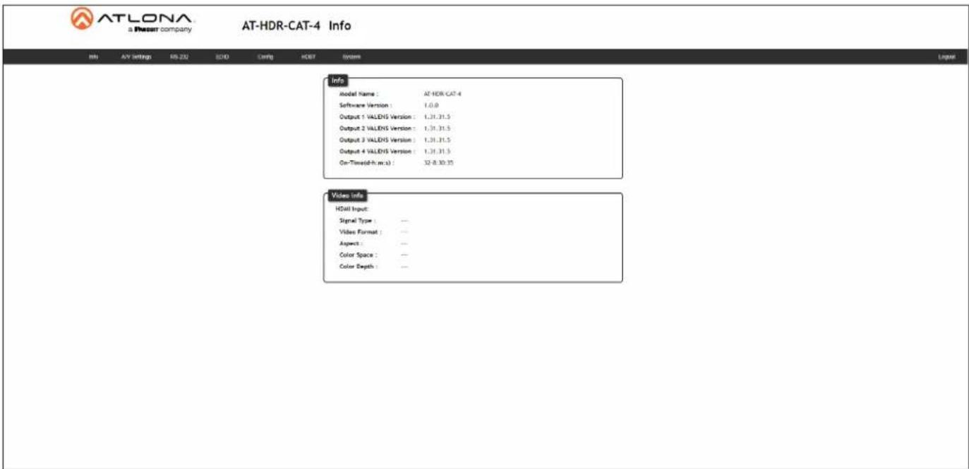
Info page
text_image
ATLONA a Present company AT-HDR-CAT-4 Info Info AV Settings EN 232 BIO Config HDBF System Info Model Name : AT-HDR-CAT-4 Software Version : 1.0.0 Output 1 VALDNS Version : 1.31.31.5 Output 2 VALDNS Version : 1.31.31.5 Output 3 VALDNS Version : 1.31.31.5 Output 4 VALDNS Version : 1.31.31.5 On-Time(d-h.m.s) : 32-8:30:35 Video Info HDMI Input: Signal Type : — Video Format : — Aspect : — Color Space : — Color Depth : —Info
Model Name
The model SKU of this product.
Software Version
The version of firmware that the AT-HDR-CAT-4 is running. Always make sure to check the AT-HDR-CAT-4 product page, on the Atlona web site, for the latest version of firmware.
Output VALENS Version
The version of firmware on the HDBaseT chip for HDBaseT OUT 1 - HDBaseT OUT 4.
On-Time (d-h:m:s)
Displays the amount of time elapsed since the unit was powered.
Video Info
Displays signal information on the HDMI input.
Signal Type
The type of input signal.
Video Format
The input resolution of the source device.
Aspect
Aspect ratio of the input signal.
Color Space
Displays the color space and chroma sub-sampling of the input signal.
Color Depth
The color depth of the input signal.
Configuration and Management Interfaces
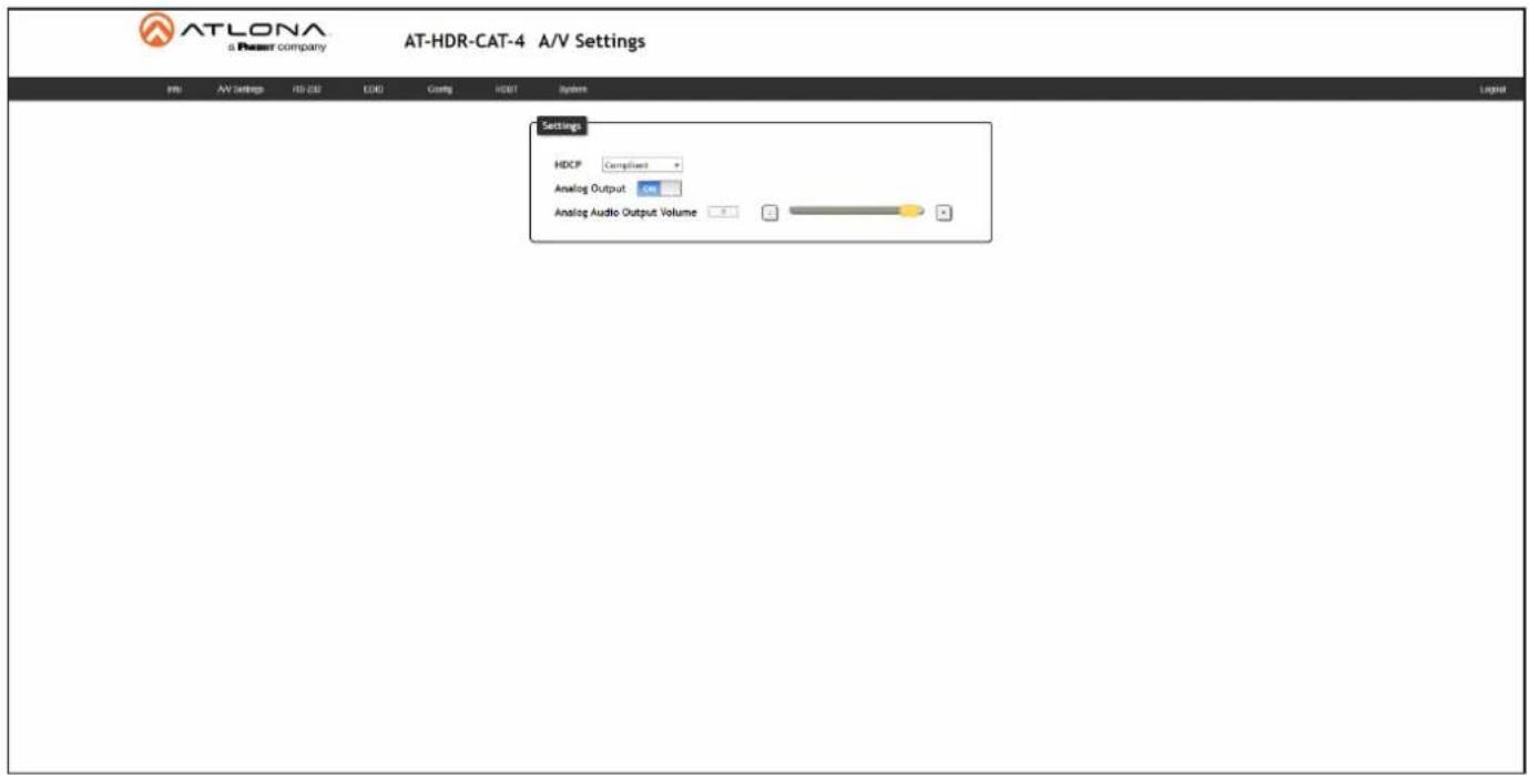
A/V Settings page
text_image
AT-LONA a Power company AT-HDR-CAT-4 A/V Settings HDL AV Settings RD 232 EOG Comptg HDBT System Settings HDCP Compliant Analog Output ON Analog Audio Output VolumeSettings
HDCP
Click this drop-down list to select the HDCP reporting mode.
| Setting Description | |
| Compliant Allows the source | device to send HDCP content to an HDCP-compliant display. This is the default setting. |
| Non-compliant Will attempt | to force the source device to ignore detection of HDCP-compliant displays, allowing non-HDCP content to be transmitted from the source (if possible). Note that some source devices, such as PlayStationTM console systems and Mac® computers always send HDCP content. Selecting the Non-compliant option will not decrypt or circumvent HDCP-protected content. |
Analog Output
Click this toggle switch enable or disable audio output on the AUDIO OUT port.
| Setting Description | |
| ON Audio is de-embedded and sent to the AUDIO OUT port. | |
| OFF Audio is disabled on the AUDIO OUT port. | |
Analog Audio Output Volume
Click and drag this slider to adjust the audio volume on the AUDIO OUT port.
Configuration and Management Interfaces
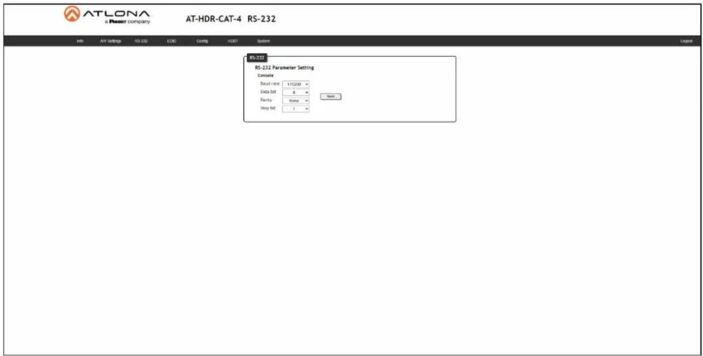
RS-232 page
text_image
ATLONA a Resort company AT-HDR-CAT-4 RS-232 RS-232 RS-232 Parameter Setting Console Dead rate 115200 Data bit 8 Parity None Mop bit 1 SaveRS-232
RS-232 Parameter Setting
Click each of these drop-down boxes to select the desired baud rate, data bits, parity bit, and stop bit for the MASTER RS-232 / IR port.
| Setting Description | |
| Baud rate Sets the baud rate. | The following options are available: 2400, 9600, 19200, 38400, 56000, 57600, 115200. |
| Data bit Sets the number of data bits used to represent each character of data. | The following options are available: 7 or 8. |
| Parity Sets the parity bit, which can be included with each character to detect errors during the transmission of data. | The following options are available: None, Odd, or Even. |
| Stop bit Sets the stop bit. | Stop bits are sent at the end of each character, allowing the client to detect the end of a character stream. The following options are available: 1 or 2. |
Configuration and Management Interfaces
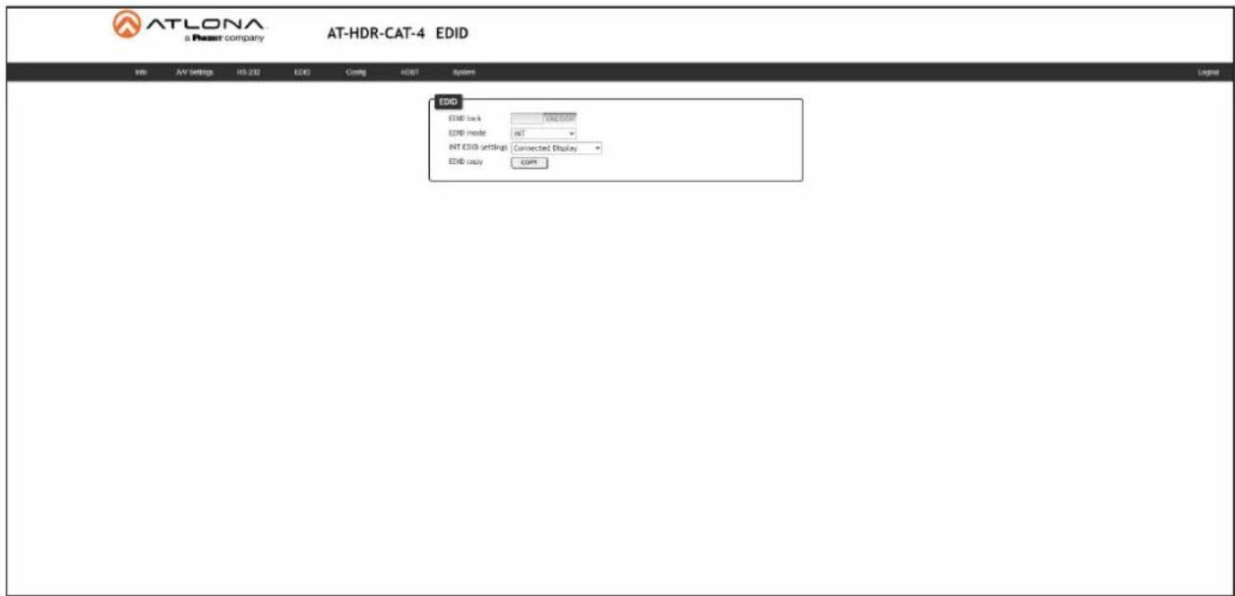
EDID page
text_image
ATLONA a Power company AT-HDR-CAT-4 EDID EVID Link: INFOCOM EDID mode: INT INT EVID settings: Connected Display EDID copy: COMEDID
EDID lock
Click this toggle to switch the EDID lock mode. When set to the LOCK position, the LOCK LED indicator on the front panel will glow solid blue. Note that in this mode, all front-panel buttons are locked.
EDID mode
Click this drop-down list to select the desired EDID mode.
| Setting Description | |
| INT Internal mode. Uses the selected internal EDID.LEARN Learn mode. Allows the AT-HDR-CAT-4 to read the downstream EDID. Once the EDID is learned, it will be used by the connected source device to determine what video and audio formats can be sent to the sink device. Refer to EDID Management (page 19) for more information. | |
INT EDID settings
Click this drop-down list to select the desired EDID.
| EDID Description | |
| Connected Display Uses the downstream EDID of the connected display | |
| ATL 4K60 MCH 3840 x 2160 (UHD) with multichannel audio support | |
| ATL 4K60 PCM MCH 3840 x 2160 (UHD) with PCM multichannel audio support | |
| ATL 1080P MCH 1920 x 1080p with multichannel audio support | |
| ATL 1080P 2CH 1920 x 1080p with two-channel audio support | |
| ATL 1080P DD 1920 x 1080p with Dolby | TM Digital audio support |
| ATL 1080P DVI 1920 x 1080p for DVI displays | |
| ATL 720P DD 1280 x 720p with Dolby | TM Digital audio support |
| ATL 720P 2CH 1280 x 720p with two-channel audio support | |
EDID copy
Click this button to copy the selected EDID to the HDMI IN port.
Configuration and Management Interfaces
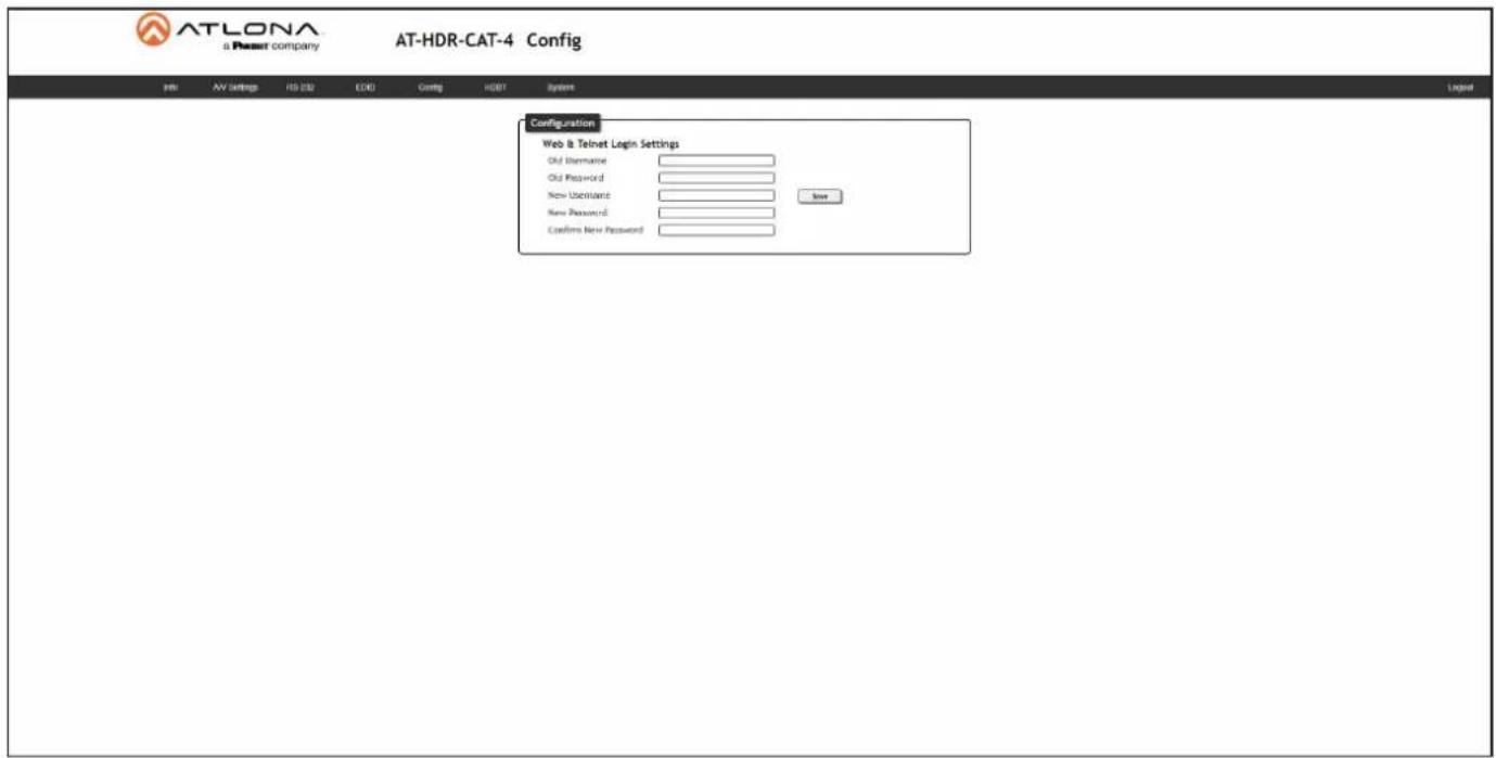
Config page
text_image
ATLONA a Petest company AT-HDR-CAT-4 Config Configuration Web & Telnet Login Settings Old Username: Old Password: New Username: New Password: Confirmed New Password:Configuration
Old Username
Enter the current username in this field.
Old Password
Enter the current password in this field.
New Username
Enter the new username in this field.
New Password
Enter the new password in this field.
Confirm New Password
Verify the new password by retyping it in this field.
Save
Click this button to apply all changes.
Configuration and Management Interfaces
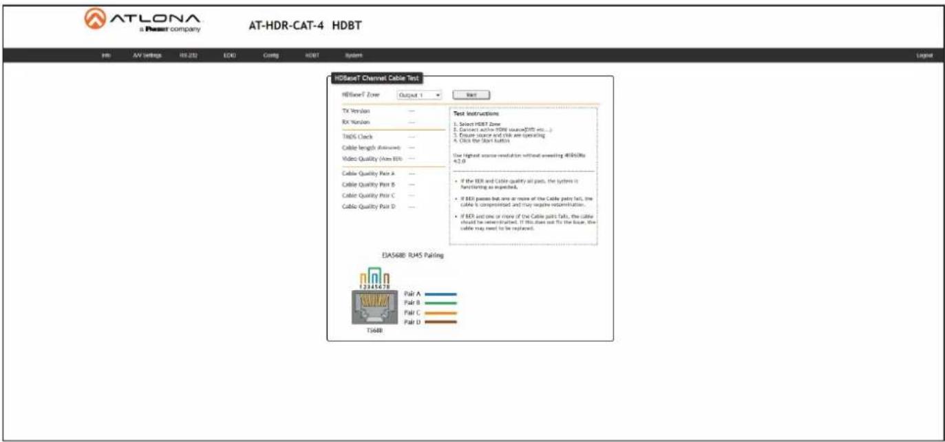
HDBT page
text_image
ATLONA a Resort company AT-HDR-CAT-4 HDBT PHI AV Settings H3.232 EOG Ctrl: HDBT System HDBaseT Channel Cable Test HDBaseT Zone Output 1 Next TX Version — RX Version — Ti605 Check — Cable length (Minimum) — Video Quality (Max 80%) — Cable Quality Pair A — Cable Quality Pair B — Cable Quality Pair C — Cable Quality Pair D — Test Instructions 1. Select HDBT Zone 2. Contact active HDB source(200 bits...) 3. Ensure square and VBA are operating 4. Click the Start button The highest source resolution without switching HDB680e 4x2.0 If the IER and Cable quality all pass, the system is functioning as expected. If IER passes but one or more of the Cable pairs fail, the cable is compromised and may negative recombination. If IER and one or more of the Cable pairs fails, the cable should be synthesized. If this does not fix the base, the cable may need to be replaced. EA568B RMS Pairing 12345478 Pair A Pair B Pair C Pair D Ts688HDBaseT Channel Cable Test
HDBaseT Zone
Click this drop-down list to select the desired HDBaseT output to be tested.
| Setting Description Setting Description | ||
| Output 1 HDBaseT OUT 1 Output 3 HDBaseT OUT 3 | ||
| Output 2 HDBaseT OUT 2 Output 3 HDBaseT OUT 4 |
Start
Click the Start button to begin the HDBaseT testing process. During testing, the button text will change to "Stop". Click the Stop button to halt the HDBaseT testing process. HDBaseT testing can be performed at any time, while the unit is powered. Refer to the instructions on this web page for information on how to interpret the Bit Error Rate (BER) and cable test results.
TX Version
The version of the Valens chip on the transmitter.
RX Version
The version of the Valens chip on the receiver.
TMDS Clock
Displays the pixel clock speed. If no source is connected, then this field will display as "None".
Cable length (Estimated)
This field indicates the approximate length of the category cable connected between the HDBaseT port on the AT-HDR-CAT-4 and the receiver. If the cable length is less than 15 feet, then this value will be displayed as 0 (zero).
Video Quality (Video BER)
The Bit Error Rate (BER). This field displays either PASS or FAIL during a test.
Cable Quality Pair (A, B, C, D)
Each of these fields will display either PASS or FAIL during a test.
Configuration and Management Interfaces
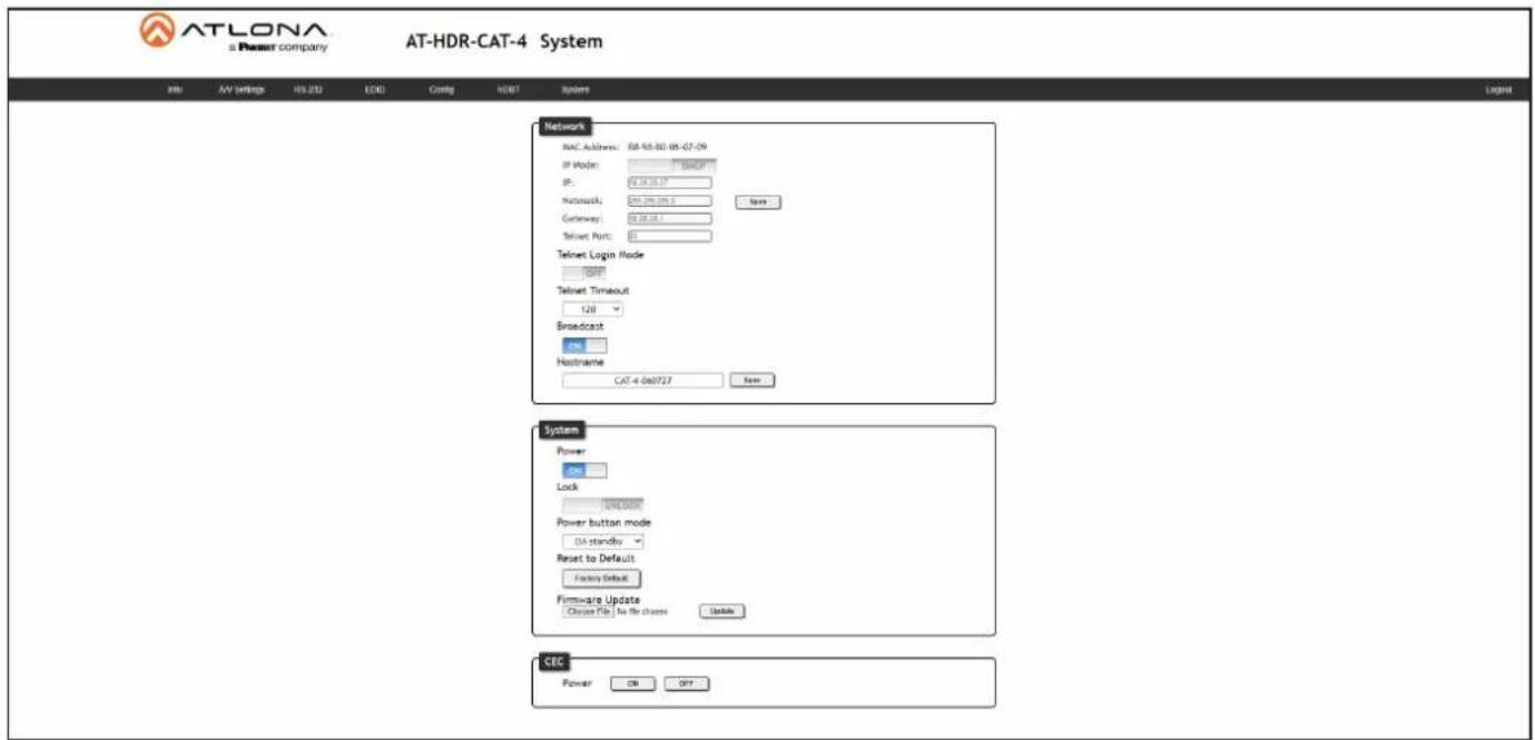
System page
text_image
ATLONA a Power company AT-HDR-CAT-4 System FRI AV Settings H3 232 EDD Config HDBT System Legend Network MAC Address: 88-95-80-05-07-09 IP Mode: 100000000000000000000000000000000000000000000000000000000000000000000 IP: 67.16.16.17 Network: 67.16.16.17 Gateway: 67.16.16.17 Telnet Port: 67 Telnet Login Mode 1288 Telnet Timeout 128 Broadcast OK Hostname CAT-4-060727 Save System Power OK Lock POWER Power button mode D4 standby Reset to Default Factory Default Firmware Update Choose File No the chosen Update CEC Power ON OFFNetwork
MAC address
Displays the MAC address of the AT-HDR-CAT-4.
IP Mode
Click this toggle to set the IP mode of the AT-HDR-CAT-4.
| Setting Description | |
| DHCP Uses an available DHCP server to assign an IP address. | |
| STATIC IP Allows the IP address, subnet mask, and gateway IP address to be entered manually. | |
IP
Enter the IP address of the AT-HDR-CAT-4 in this field. This field will only be available if IP Mode is set to STATIC IP. The default static IP address is 192.168.1.254.
Netmask
Enter the subnet mask in this field. This field will only be available if IP Mode is set to STATIC IP.
Gateway
Enter the gateway (router) address in this field. This field will only be available if IP Mode is set to STATIC IP.
Telnet Port
Enter the Telnet listening port in this field.
Telnet Login Mode
Click this toggle to set the login mode to either ON or OFF. If this feature is set to ON, then use the same login credentials as the web server.
| Setting Description | |
| ON The AT-HDR-CAT-4 will | prompt for both the username and password at the start of a Telnet session. |
| OFF No username and password is required for Telnet sessions. | |
Configuration and Management Interfaces
Telnet Timeout
Click this drop-down list to select the timeout interval, in seconds, before the Telnet connection is automatically closed after no activity. Range: 1 to 3600 (seconds).
Broadcast
This option determines whether or not systems changes are announced over TCP/IP connections to any listening devices.
| Setting Description | |
| ON System changes will be | announced over TCP/IP connections to any device that has a TCP/IP connection to the AT-HDR-CAT-4. This is the default setting. |
| OFF only the device that is | sending the commands will receive feedback from the commands or any system changes. Read queries, such as the IPCFG and Type commands, are not announced and will only return information to the requester. |
Hostname
Displays the hostname of the AT-OME-MS42, as it would appear on a network. To change the hostname, type the new hostname in this field and click the Save button. Refer to Setting the Host Name (page 35) for more information.
System
Power
Determines the power state of the AT-HDR-CAT-4.
| Setting Description | |
| ON Under normal operation | conditions, this toggle is set to ON. |
| OFF | Places the AT-HDR-CAT-4 in standby mode. The PWOFF and PWON commands can also be used to control the power state. |
Lock
Click to lock or unlock the buttons on the front panel. Locking the front panel buttons is useful in preventing accidental button activation within rack environments.
| Setting Description | |
| LOCK Locks the front panel | buttons. |
| UNLOCK Unlocks the front | panel button, allowing them to be functional. |
Configuration and Management Interfaces
Power button mode
Click this drop-down list to select the desired function of the power button. Refer to Power Button Modes (page 31) for more information.
| Setting Description | |
| DA standby | Pressing the POWER button will toggle the AT-HDR-CAT-4 between standby mode and normal operating mode. |
| CEC* When a sink device (display) is connected to the AT-HDR-CAT-4, pressing the POWER button will toggle the power state of the display using the CEC protocol. The power state of the AT-HDR-CAT-4 is unaffected. Power-on and power-off commands are sent over both the HDBaseT OUT and HDMI OUT ports | |
| Both | Pressing the POWER button will toggle the power state of both the AT-HDR-CAT-4 and any sink devices that are connected to the AT-HDR-CAT-4, using the CEC protocol. Power-on and power-off commands are sent over both the HDBaseT OUT and HDMI OUT ports. |
Reset to Default
Click the Factory Default button to set the AT-HDR-CAT-4 to factory-default settings.
Firmware Update
Click the Choose File button to select the firmware file, when upgrading the firmware on the AT-HDR-CAT-4. Once the firmware file is selected, click the Update button. Refer to Updating the Firmware (page 49) for more information.
CEC
ON / OFF
Click these buttons to test CEC control between the AT-HDR-CAT-4 and the connected sink device. Click the ON button to power-on the device and OFF to power-off the device. Refer to Power Button Modes (page 31) for more information.
| Button Description | |
| ON Sends the CEC command to power-on the device. | |
| OFF Sends the CEC command to power-off the device. | |
*Consumer Electronics Control (CEC): Atlona has confirmed proper CEC functionality with several current models of Samsung, Panasonic, and Sony displays. However, it is not guaranteed that CEC will work with all displays. Many manufacturers do not support the CEC "off" command, and older displays use proprietary commands. Atlona only supports displays that use the CEC command structure defined in HDMI 1.2a. It is recommended that dealers request an evaluation product from Atlona, before designing a system using the CEC protocol. If this is not possible, then other control methods will need to be considered, in order to control displays using Atlona products.
Appendix
Updating the Firmware
Updating the firmware can be completed using either the USB interface or the web server. Atlona recommends using the web server for updating the MCU firmware. However, if a network connection is not available, the AT-HDR-CAT-4 firmware can be updated using a USB-A to USB-C cable.
Using the Web Server
Requirements:
- AT-HDR-CAT-4
- Firmware file
-
Computer
-
Connect an Ethernet cable from the computer, containing the firmware, to the same network where the AT-HDR-CAT-4 is connected.
- Log in to the web server and go to the System page (page 46).

text_image
ATLONA a Passur company AT-HDR-CAT-4 System Help Help Settings HS-232 CDDI Coding HDBT System Network MAC Address: SR-90-50-01-07-04 IP Mode: 0.0000 IP: 0.0000 Network: 0.0000 Gateway: 0.0000 Telnet Port: Telnet Login Mode 5687 Telnet Timeout 120 Broadcast 5ms MacName: CAT + 0x0727 Load Choose File button System Power Up Lock FIREBOOK Power button mode Set standby Faster Default Furniture Update Create File No Be chosen Choose CEC Power On Off- Click the Choose File button, under Firmware Update.
- Browse to the location of the firmware file, select it, and click the Open button.
- Click the Update button to begin the update process. The following message box will be displayed.

text_image
10.0.1.107 says: Are you Sure want to update Firmware? OK Cancel-
Click the OK button to begin the firmware update process. Click the Cancel button to cancel the process.
-
After the firmware update process is complete, the Login screen will be displayed, indicating that the update process is complete.
Appendix
Using USB
Required items:
-
AT-HDR-CAT-4
• Computer containing the firmware file.
• USB-A to USB-C cable -
Disconnect power from the AT-HDR-CAT-4.
-
Press and hold the EDID button while connecting power to the AT-HDR-CAT-4.
-
Release the EDID button. The POWER button will glow solid red, indicating that the AT-HDR-CAT-4 is in update mode.
-
Connect the USB-A to USB-C cable between the PC and the firmware port on the AT-HDR-CAT-4.
-
A virtual USB drive will be displayed in a pop-up window.
-
Delete all files from the virtual drive, if any are present.
-
Drag-and-drop the firmware file to the drive. During the firmware update procedure, the POWER button will flash.
-
After the file has been copied, disconnect the USB cable from both the computer and the AT-HDR-CAT-4.
-
The firmware update process is complete.
Default Settings
The following tables list the factory-default settings for the AT-HDR-CAT-4.
| Feature Setting Value | ||
| A/V Settings HDCP | Compliant | |
| Analog Output | ON | |
| Analog Output Volume | 0 | |
| RS-232 Baud rate | 115200 | |
| Data bit | 8 | |
| Parity | None | |
| Stop bit | 1 | |
| EDID EDID lock | UNLOCK | |
| EDID mode | INT | |
| INT EDID settings | Connected Display | |
| System IP Mode | DHCP | |
| Static IP Address (default) | 192.168.1.254 | |
| Netmask | 255.255.0.0 | |
| Gateway | 192.168.1.1 | |
| Telnet Port | 23 | |
| Telnet Login Mode | OFF | |
| Telnet Timeout | 120 | |
| Broadcast | ON | |
| Power | --- | |
| Lock | UNLOCK | |
| Power button mode | DA standby | |
Specifications
| Video | ||
| Signal Input - HDMI | Output - HDMI / HDBaseT | |
| Copy Protection HDCP 2.2 | ||
| Pixel Clock 600 MHz | ||
| UHD/HD/SD 4096x2160 (DCI) @ 24/25/30/50/60 Hz | 720x576p @ 50 Hz | |
| 3840x2160 (UHD) @ 24/25/30/50/60 Hz | 720x576i @ 25/50 Hz | |
| 1920x1080p @ | 720x480p @ 60 Hz | |
| 23.97/24/25/29.97/30/50/60 Hz | 640x480p @ 60 Hz | |
| 1920x1080i @ 50/60 Hz | ||
| 1280x720p @ 30/50/60 Hz | ||
| VESA 2560x1600 @ 60 Hz (RB) | 1366x768 @ 60 Hz | |
| 2048x1536 @ 60 Hz | 1360x768 @ 60 Hz | |
| 2048x1200 @ 60 Hz | 1280x1024 @ 60 Hz | |
| 2048x1080 @ 60 Hz | 1280x800 @ 60 Hz | |
| 1920x1200 @ 60 Hz (RB) | 1280x768 @ 60 Hz | |
| 1920x1080 @ 60 Hz (RB) | 1280x720 @ 60 Hz | |
| 1680x1050 @ 60 Hz | 1024x768 @ 60 Hz | |
| 1600x1200 @ 60 Hz | 800x600 @ 60 Hz | |
| 1600x900 @ 60 Hz | 640x480i @ 29.97/30 Hz | |
| 1440x900 @ 60 Hz | ||
| 1400x1050 @ 60 Hz | ||
| Color Space YUV, RGB | ||
| Chroma Subsampling 4:4:4, 4:2:2, 4:2:0 | ||
| Color Depth 8-bit, 10-bit, 12-bit | ||
| HDR HDR10, Hybrid-Log Gamma (HLG), and Dolby® VisionTM @ 60 Hz | ||
| Audio | |||
| HDMI / HDBaseTPass-Through Formats | PCM 2.0LPCM 5.1LPCM 7.1 | Dolby®DigitalDolby Digital PlusTMDolby TrueHDDolby Atmos® | DTS®Digital SurroundTM DTS-HD Master AudioTM DTS:X® |
| Bit Depth Up to 24 bits | |||
| Analog Audio | |||
| Format Stereo 2-Channel | |||
| Balanced Output +4 dBu nominal gain, +19 dB headroom | |||
| Frequency Response 20 Hz to 20 kHz, ± 0.5 dB | |||
| THD+N | < 0.006% at 20 Hz to 20 kHz | ||
| SNR | >105 dB at 1 kHz, zero clipping @ 0 dBFS, unweighted | ||
| Sample Rate | 32 kHz, 44.1 kHz, 48 kHz, 88.2 kHz, 96 kHz, 176.4 kHz, 192 kHz | ||
| Ethernet | |
| Port | 1 x RJ45 |
| Standards and Protocols | HTTP, HTTPS, Telnet, mDNS |
| Speeds | 10/100 Mbps |
| Addressing | DHCP, Static – selectable through front panel, IP & RS-232 commands, and built-in web server |
Appendix
| RS-232 | ||
| Port | 5 x 5-pin captive screw | |
| Use | Unit and external device control and configuration | |
| Baud Rates 2400, 4800, 9600, | 19200, 38400, 57600, 115200 | |
| Data Flow | Bidirectional | |
| IR | ||
| Port | 5 x 5-pin captive screw | |
| Use | Pass-through from control system to sink devicePass-through from viewing location to source | |
| Frequency Range | 30 kHz to 60 kHz | |
| CEC | |
| Ports | 1 x HDMI OUT, Type A, 19-pin female; 4 x RJ45 (HDBaseT OUT) |
| Triggering | Through IP, RS-232, and built-in web server |
| Resolution / Distance | 4K/UHD - Feet / Meters | 1080p - Feet / Meters | ||
| HDMI IN/OUT | 15 | 5 | 30 | 10 |
| CAT5e/6 | 115 | 35 | 200 | 60 |
| CAT6a/7 | 130 | 40 | 230 | 70 |
| Buttons and Indicators | |
| Buttons:POWER, EDID | 2 x momentary, tact-type |
| Indicators:HDMI IN/OUT,HDBaseT (1 - 4), LOCK,INT, LEARN | 9 x LED, blue |
| Connectors | |
| HDMI IN 1 x Type A, 19-pin female | male |
| HDMI OUT 1 x Type A, 19-pin female | |
| HDBaseT OUT 4 x RJ45 | |
| LAN 1 x RJ45 | |
| AUDIO OUT 1 x 5-pin captive screw | |
| RS-232 / IR 5 x 5-pin captive screw | |
| FW 1 x USB-C | |
| DC 48V 1 x 2-pin captive screw | |
| Environmental Fahrenheit Celsius | |||
| Operating Temperature +32 to +122 0 to +50 | |||
| Storage Temperature -4 to +140 -20 to +60 | |||
| Operating Humidity (RH) | 20% to 90%, non-condensing | ||
| Power | ||
| Consumption (w/ 4 PoE) | 70.6 W | |
| Idle Consumption (no PoE) | 10.6 W | |
| BTU/h | 36.2 | |
| External Power Supply | 100 - 240 V AC, 50/60 HzOutput: 48 V / 2.08 A DC | |
Appendix
| Dimensions (H x W x D) Inches Millimeters | ||
| Unit 1.73 x 8.64 x 10 44 x 219.5 x 254 | ||
| Power Supply(AT-PS-48208-C) | 1.3 x 2.24 x 5.35 33 x 57 x 136 | |
| Weight Pounds Kilograms | ||
| Device 3.75 1.7 |
| Certification | ||
| Device CE, RoHS, FCC | ||
| Power Supply CE, FCC, UL, CUL, TUV-GS, CB, PSE, CCC | ||
| Compliance | |
| NDAA-889 Yes | |
| TAA Yes | |