
BRDN080-1034TL - Inverter Geist - Free user manual and instructions
Find the device manual for free BRDN080-1034TL Geist in PDF.

| Product Type | Rack Power Distribution Unit (PDU) - VRTD, BRD, VRE Series |
| Model | BRDN080-1034TL |
| Brand | Geist (a division of Vertiv, Inc.) |
| Input Rating | 30 Amp AC Mains circuit |
| Voltage Rating | 125 V (for BRD series) |
| Receptacle Types | NEMA 5-20R/L5-20R (125V, 16A) and IEC-60320 C13 (250Vac, 10A) |
| Overcurrent Protection | Single pole thermal breakers per output receptacle |
| Operating Temperature | 10°C to 45°C (50°F to 113°F) |
| Storage Temperature | -25°C to 65°C (-13°F to 149°F) |
| Operating Humidity | 5% to 95% non-condensing |
| Operating Elevation | 0 to 3,050 m (10,000 ft) |
| Compliance | UL listed, FCC Class A, Canadian ICES-003, WEEE, TAA, Buy American |
| Mounting Options | Full length bracket, mini L brackets, vertical extension brackets, toolless mounting, offset/side mount, flush mount, adjustable mount, panel mount, 23" conversion brackets |
| Optional Local Metering | PM-1 Power Meter or CM-1 Current Meter (true RMS current, voltage, power, power factor) |
| Local Display | 4-digit LED display, auto-scrolling |
| Safety | For restricted access locations; must be connected to earthed socket; indoor use only |
| Service | No user-serviceable parts; do not open; contact support |
| Warranty | Standard Geist warranty (details on request) |
Frequently Asked Questions - BRDN080-1034TL Geist
User questions about BRDN080-1034TL Geist
0 question about this device. Answer the ones you know or ask your own.
Ask a new question about this device
Download the instructions for your Inverter in PDF format for free! Find your manual BRDN080-1034TL - Geist and take your electronic device back in hand. On this page are published all the documents necessary for the use of your device. BRDN080-1034TL by Geist.
USER MANUAL BRDN080-1034TL Geist
natural_image
Orange hexagonal logo with abstract geometric shapes (no text or symbols)GEIST
POWER
Instruction Manual
Rack PDU
VRTD, BRD, and VRE Series
Table of Contents
Introduction 4
Welcome....4
About this Manual 7
Revision History....7
Organization of the Manual....7
Audience Profile....7
On-line Documentation....8
Reporting Document Errors....8
Conventions....8
Software 8
Hardware 8
Safety 10
Figures 11
Tables 11
Chapter 1 - Product Specifications 12
Overview.... 12
Environmental.... 12
Temperature 12
Humidity 12
Elevation 12
Electrical.... 13
Receptacle Ratings 13
Regulatory Compliance.... 13
Underwriters Laboratories (UL) 13
Federal Communications Commission (FCC) 13
Chapter 2 - Installation 14
Pre-Installation.... 14
Installation.... 15
Mounting 15
Chapter 3 - Optional Local Metering 24
Power Meter.... 24
Current Meter.... 25
Service/Tech Support 25
Service and Maintenance.... 25
More Technical Support.... 25
Introduction
Welcome
Notice to Users
Geist, a division of Vertiv, Inc., reserves the right to make changes to this document without notice to any user or reseller of this product. Geist, a division of Vertiv, Inc., also reserves the right to substitute or terminate distribution of this document, with no obligation to notify any person or party of such substitutions or terminations.
Copyrights
© 2018 - Geist, a division of Vertiv, Inc. All Rights Reserved.
Trademarks
All Trademarks contained herein are registered to Geist, a division of Vertiv, Inc.
Use and Disclosure Restrictions
The software and documentation contained in this publication are copyrighted materials.
Recovery Act Buy American
Geist products adhere to the Buy American provisions of the American Recovery and Reinvestment Act of 2009 (Recovery Act). All Geist goods manufactured in our Lincoln, Nebraska, plant have undergone substantial transformation during production.
Trade Agreements Act (TAA)
Geist goods manufactured in our Lincoln, Nebraska, plant have undergone substantial transformation during production. These Geist products adhere to U.S. Trade Agreements Act and can be supplied for GSA Schedules and other government contracts.
Geist Policy on Conflict Minerals
This document details Geist's corporate policy regarding the use of conflict minerals. The policy expressed in this document should be considered to cover the Geist and Geist Europe divisions of Vertiv Inc.
Section 1502 of the Dodd-Frank Act which was passed by the US Congress in 2010 requires certain companies to annually disclose their use of conflict minerals. Conflict minerals covered under this act include tantalum, tin, tungsten, and gold.
Although Geist is not directly subjected to the requirements of the Dodd-Frank Act, Geist recognizes that all companies within the electronics manufacturing industry supply chain are impacted by this legislation. Geist supports the intent of the law, which is the reduction of violence within the Democratic Republic of the Congo and will take several actions to both advance the goals of the Dodd-Frank Act and to provide exceptional support to our customers.
- Geist will work with our direct suppliers to identify purchased components and materials that contain tin, tantalum, tungsten or gold.
- Geist will work with our direct suppliers to trace sources of any tin, tantalum, tungsten or gold used in our products back to the smelter.
- Geist will document our efforts to trace tin, tantalum, tungsten, and gold minerals back to the smelter and will accurately report the results to our customers.
- Geist will continue to monitor industry progress in identifying conflict-free smelters and will adjust corporate policy as the electronics supply chain becomes more fully documented.
Geist will not require that our direct suppliers source only conflict-free minerals until an adequate number of smelters has been reliably identified and audited by The Electronic Industry Citizenship Coalition (EICC) and the Global e-Sustainability Initiative (GeSI) to service the electronic industry supply chain. Mandating a conflict-free supply chain before an adequate number of smelters has been identified will prohibit the use of all tin, tantalum, tungsten, and gold originating in the Democratic Republic of the Congo and surrounding countries. This prohibition would cut off the sole income source for many artisanal miners within the region and may result in increased violence within the Democratic Republic of the Congo in direct opposition to the goals of the Dodd-Frank Act. Geist will work continuously with our direct suppliers in order to annually increase the percentage of documented conflict-free minerals that are used in our products until all products can be certified as conflict-free.
WEEE Declaration
Geist Europe is obligated to finance the cost of the collection, treatment, recovery and environmentally sound disposal of all products sold by Geist Europe into the UK market this includes:
- New WEEE (displaying ‘the crossed out wheeled bin symbol’) that Geist Europe has placed onto the market after the 13th August 2005; and
- Historic WEEE (not displaying 'the crossed out wheeled bin symbol'), when Geist Europe is supplying new WEEE that is intended to replace the historic WEEE and is of equivalent type or fulfills the same function even if the historic WEEE was manufactured by a third party.
Please contact Geist Europe on 01823 275100 for further details or to arrange collection. (UK Only)
Document Usage
All reasonable efforts have been made to assure the accuracy of this document from any technical or typographical errors or omissions. Geist, a division of Vertiv, Inc., and its affiliates disclaim responsibility for any labor, materials, or costs incurred as a result of usage of this document. Nor shall Geist, a division of Vertiv, Inc., and its affiliates be liable for any damages, inclusive of loss of profits or data, arising from the use of or in connection with this document.
Geist, a division of Vertiv, Inc., reserves the right to make changes to this document without notice to any user or reseller of this product. Geist, a division of Vertiv, Inc., also reserves the right to substitute or terminate distribution of this document, with no obligation to notify any person or party of such substitutions or terminations.
About this Manual
This document provides an overview of Geist product(s), the major topics covered include:
• Copyright, Trademarks, and Disclosure Restrictions.
- Instructions for installing, powering and using the equipment.
• Information that will aid in managing and maintaining the equipment.
Revision History
| Revision | Date | Notes | Approved By |
| 1.0 | 11/14/2008 | Original Published Version | |
| 2.0 | 1/22/2009 | Updated GM number | |
| 3.0 | 2/12/2009 | Updated Cover Art | BGP |
| 4.0 | 6/22/2012 | Change Logo and Web Address | SR |
| 4.1 | 6/21/2017 | Updated Format | JB |
| 4.2 | 5/15/2018 | Receptacle Table and Vertiv Updates | JB |
Organization of the Manual
This Geist document contains the following product information:
- Product Specifications - This chapter describes the major product characteristics and its functional role within the system. Where appropriate, reference to cabling among product components and to other Geist product(s) is provided.
- Installation - This chapter provides installation information for the preparation and use of Geist products as well as procedures required to adequately mechanically and electrically attach Geist product into supporting systems.
- Optional Local Metering - This chapter provides information on Local Metering options for specific models.
Audience Profile
This document is intended for use by authorized technicians experienced with same of similar product types and for personnel requiring guidance for equipment installation, operation, maintenance, and support.
On-line Documentation
This document is available on-line and within the corresponding Geist Product Manuals. Additional Geist product supporting Videos, Product Literature and Case Studies can be found on the Geist Resource page.
Product firmware updates can be found and downloaded from the Geist Support site, under Firmware Updates.
Should this product fail within its warranty period and be in need of repair or replacement, a Return Material Authorization may be obtained on-line from the RMA Form link located within the Geist Support site.
Reporting Document Errors
Should you discover any error or identify a deficiency in this document, please take time to contact us at the following email address:
Geist-Documents@geistglobal.com
Please be sure to provide us with the document name, part number, and page number(s). Also, please provide us with description of the error or the deficiency for the document. If you would like for us to contact you, please provide us with your name and contact information.
Thank you for your time. We appreciate any comments and feedback you can provide.
Conventions
The information contained within this document is established around the framework of various conventions, which are defined as follows:
Software
- Release Management: Product name, Version control ; (GU V 3.0.0)
○ Product Name: Name of Hardware Platform
○ Version control: V(ersion) Platform #, Major #, Minor #
Hardware
Product Classification
- Power Distribution Unit
Basic - Monitored only
- Switched only
■ Monitored + Switched
o Environmental Monitoring
○ Cooling
○ Data Center Infrastructure Management (DCIM)
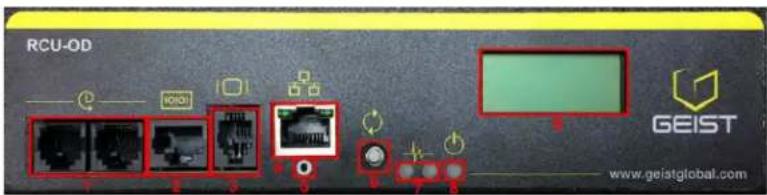
Figure 1 Overlay Symbology Guide
| Ethernet | Activity / Idle |
| Power over Ethernet | Power |
| Serial | A~ Amps |
| Remote Display | Reboot |
| Remote Sensors | Silence |
| Uplink | Scroll |
| Temp | GU Right |
| Sensor Configuration | GU Left |
| GU Center |
Figure 1 The chart above depicts the symbols used on Geist overlays.
Safety
This document contains varying levels of alerts pertaining to product and user safety. The alerts are visually presented with graphics and text per Geist equipment guidelines.
The representations are:

DANGER
INDICATES AN IMMINENT HAZARDOUS SITUATION WHICH, IF NOT AVOIDED, WILL RESULT IN DEATH OR SERIOUS INJURY.

WARNING
INDICATES A POTENTIAL HAZARDOUS SITUATION WHICH, IF NOT AVOIDED, COULD RESULT IN DEATH OR SERIOUS INJURY.

CAUTION
INDICATES A POTENTIAL HAZARDOUS SITUATION WHICH, IF NOT AVOIDED, COULD RESULT IN PRODUCT DAMAGE AND MINOR TO MODERATE INJURY.

NOTE
Provides useful information that is beneficial for operation and usage of this product.
Figures
Figures presented in this document are identified and designated as follows:
'Figure:', Chapter # - Image #
Example:
Figure 1-1 Name and/or Title goes here
Tables
Tables presented in this document are identified and designated as follows:
'Table:', Chapter # - Image #
Example:
Table 1-1 Name and/or Title goes here
| Column 1 | Column 2 | Column 3 | Column 4 | Column 5 |
| Text | Text | Text | Text | Text |
| Text | Text | Text | Text | Text |
| Text | Text | Text | Text | Text |
| Text | Text | Text | Text | Text |
Chapter 1 - Product Specifications
Overview
The VRE, VRTD, and BRD Series products are Power Distribution Units (PDU) intended for connection to a 30 Amp AC Mains circuit. The PDUs utilize single pole thermal breakers for supplementary over-current protection of the output receptacles. The VRTD Series is available in vertical configurations rated 125 V, while the BRD Series is available in horizontal configurations rated 125 V. The VRE Series is available in vertical configurations rated either 125 or 250 V. The VRE, VRTD, and BRD Series PDUs can optionally be configured with a Geist Power Meter that provides local monitoring and display of Current, Voltage, Wattage, and Power Factor.
Environmental
Temperature
Table 1-1 Temperature Limits
| Minimum | Maximum | |
| Operating | 10°C (50°F) | 45°C (113°F) |
| Storage | -25°C (13°F) | 65°C (149°F) |
Humidity
Table 1-2 Humidity Limits
| Minimum | Maximum | |
| Operating | 5% | 95% (non-condensing) |
| Storage | 5% | 95% (non-condensing) |
Elevation
Table 1-3 Elevation Limits
| Minimum | Maximum | |
| Operating | 0 m (0 ft) | 3,050 m (10,000 ft) |
| Storage | 0 m (0 ft) | 15,240 m (50,000 ft) |
Electrical
Electrical product characteristics an performance are defined below. Also, please see the product nameplate for additional rating limits.
Receptacle Ratings
Table 1-4 Receptacle Ratings
| Type | Ratings |
| NEMA 5-20R or L5-20R | 125 Volts, 16 Amp |
| NEMA 6-20R or L6-20R | 250 Volts, 16 Amp |
| IEC-60320 C13 | 250Vac, 10A (UL & CSA 12A, 250Vac) |
Regulatory Compliance
Geist products are regulated for Safety, Emissions, and Environment Impact per the below agencies and policies.
Underwriters Laboratories (UL)
UL Standards are used to assess products; test components, materials, systems and performance; and evaluate environmentally sustainable products, renewable energies, food and water products, recycling systems and other innovative technologies.
The UL standards specific to this equipment are as noted on the device nameplate.
Federal Communications Commission (FCC)
The Federal Communications Commission (FCC) regulates interstate and international communications by radio, television, wire, satellite, and cable in all 50 states, the District of Columbia and U.S. territories. An independent U.S. government agency overseen by Congress, the commission is the United States' primary authority for communications laws, regulation and technological innovation.
The FCC standards specific to this equipment are:
This Class A device complies with part 15 of the FCC Rules. Operation is subject to the following two conditions: (1) This device may not cause harmful interference, and (2) this device must accept any interference received, including interference that may cause undesired operation.
This Class A digital apparatus complies with Canadian ICES-003.
CHANGES OR MODIFICATIONS TO THIS UNIT NOT EXPRESSLY APPROVED BY THE PARTY RESPONSIBLE FOR COMPLIANCE COULD VOID THE USER'S AUTHORITY TO OPERATE THIS EQUIPMENT.
Chapter 2 - Installation
Pre-Installation
• Install the PDU such that the amount of airflow required for safe operation of equipment is not compromised.
- Mount the PDU so that a hazardous condition is not achieved due to uneven mechanical loading.
- Follow nameplate ratings when connecting equipment to the branch circuit. Take into consideration the effect that overloading of the circuits might have on overcurrent protection and supplied wiring.
- The PDU relies on the building installation for protection from overcurrent. A certified overcurrent protection device is required in the building installation. The overcurrent protection device should be sized according to the PDU's nameplate ratings and local/national electrical code.
- Reliable earthing of rack-mount equipment should be maintained. Particular attention should be given to supply connections other than direct connections to the branch circuit. The PDU must be connected to an earthed socket outlet.
- PDU is intended for restricted-access locations. Only qualified service personnel should install and access the PDU.
- For pluggable equipment, install the PDU so the input plug or appliance coupler may be disconnected for service.
- The PDU is intended for indoor use only. Do not install the unit in wet or outdoor environments, and do not install it next to water tanks or plumbing.
- The PDU is intended for use with TN, TT, or IT power supply systems.
Installation
- Using appropriate hardware, mount PDU to rack (see Mounting section for additional instructions.
- Plug PDU into de-energized 30 Amp branch circuit receptacle.
- Connect devices into PDU's output receptacles. It is recommended that the devices are turned off until all devices are connected to PDU
- Turn on 30 Amp branch circuit to energize PDU.
- Power on devices. Sequential power up is recommended to avoid high inrush current.
Mounting
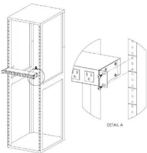
Figure 2-1 Full Length Bracket
Full Length Bracket
Using the full length bracket, mount PDU to rack as shown.
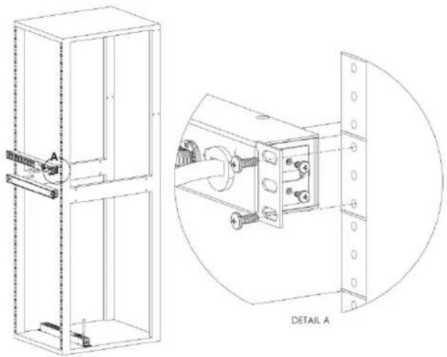
Figure 2-2 Mini L Brackets

Mini "L" Brackets (SLB-4)
Using the mini "L" brackets, attach PDU to rack as shown.
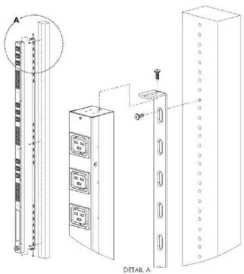
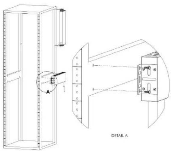
Figure 2-3 Vertical Extension Brackets
Vertical Extension Brackets (VCB-1)
Using the vertical extension brackets, attach PDU to rack as shown.
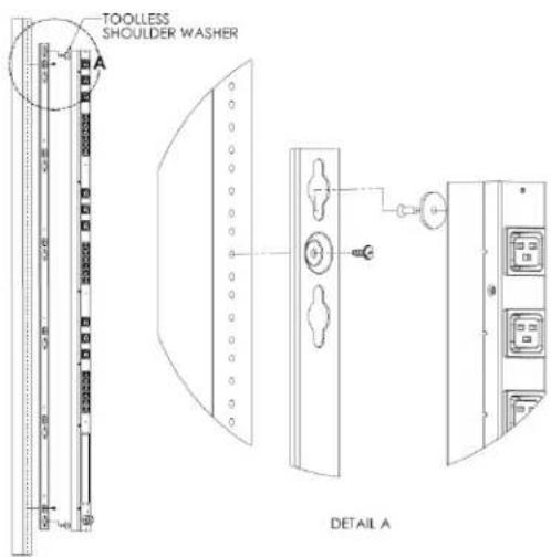
Figure 2-4 Toolless Mounting Hardware
Toolless Mounting Hardware (11621)
Secure toolless mounting buttons to PDU as shown. Use toolless buttons with key-holed slots built into cabinet or with optional Geist key-holed brackets.
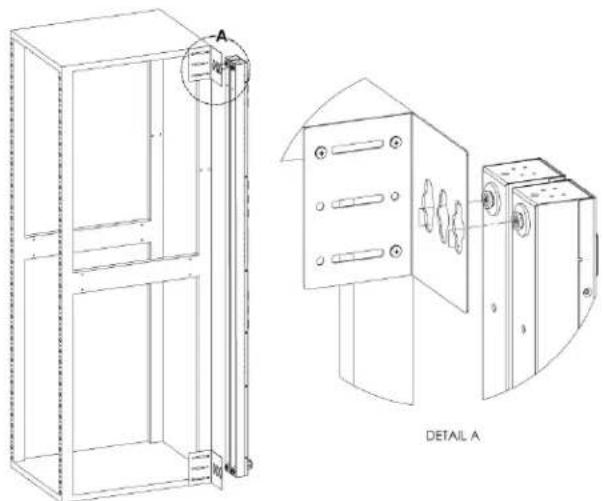
Figure 2-5 Toolless Full Length Brackets
Toolless Full Length Bracket (TLFL)
Using full length toolless bracket and toolless mounting buttons, attach PDU to rack as shown.
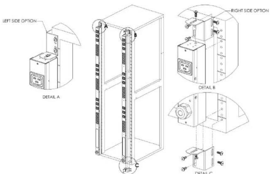
Figure 2-6 Single Side Mount 2 Units Brackets
natural_image
Technical line drawing of a cabinet with an elevator and a mechanical device (no text or symbols)Single Side Mount Two Unit Brackets (TSMX2)
Using single side mount two unit brackets and toolless mounting buttons, attach PDU to rack as shown.
Figure 2-7 Offset/Side Mount Brackets
Offset/Side Mount Brackets (EZB-1)
Using the offset/side mount brackets, attach PDU to rack as shown.
Figure 2-8 7" Extension Brackets
7" Extension Brackets (XB-7)
Using the 7" extension brackets, attach PDU to rack as shown.
Figure 2-9 Flush Mount Brackets
Flush Mount Brackets (FM)
Using flush mount brackets, attach PDU to rack as shown.
Figure 2-10 Adjustable Mount Brackets
Adjustable Mount Brackets (AM)
Using adjustable mount brackets, attach PDU to rack as shown.
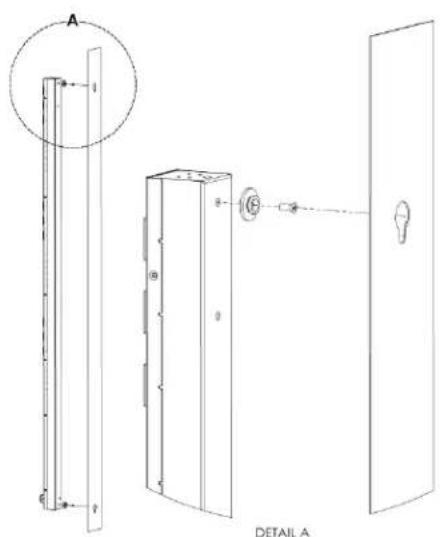
Figure 2-11 Panel Mount Brackets
Panel Mount Brackets (PM)
Using panel mount brackets, attach PDU to rack as shown.
Figure 2-12 23" Conversion Mounting Brackets

23" Conversion Mounting Brackets (23-RM)
Using conversion mounting brackets, attach 19" PDU to 23" rack as shown.
Figure 2-13 Cable Mount Brackets
Cable Mount Bracket (CMB-1)

Attach cable mount bracket to PDU as shown; use tie-wraps to secure cords to bracket.
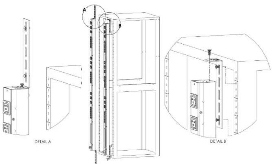
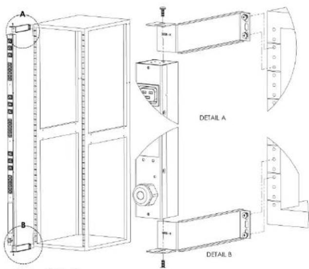
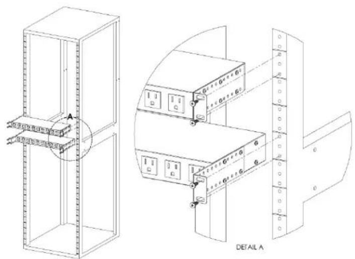
Figure 2-14 19" Horizontal/Panel Mount Brackets
natural_image
Technical line drawing of a mechanical assembly with two views: top shows a vertical frame with internal components, bottom shows a close-up of a mechanical component (no text or symbols)19" Horizontal/Panel Mount Brackets (7938)
Using the 19" horizontal/panel mount brackets, attach PDU to rack as shown.
Chapter 3 - Optional Local Metering
Power Meter
The Geist PM-1 power meter is a low-power, high accuracy meter capable of measuring true RMS Current, Voltage, Power, and Power Factor. These values are individually shown on an easy to read, 4-digit LED Display, which continuously scrolls through the four different measured values. Each one of these displayed parameters is defined below. The Power Meter will automatically begin cycling through the displayed values when the PDU is connected to AC Mains power.
- Current: PDU output current draw measured in true RMS Amps.
• Voltage: PDU output voltage measured in true RMS Voltage.
• Power: PDU output power measured in Watts – referred to as real or active power. - Power Factor: Ratio of real PDU output power to apparent PDU output power.
Figure 3-1 Power Meter

Power Meter Display
Current Meter
The Geist CM-1 current meter is a low-power, high accuracy meter capable of measuring true RMS Current. The value of current is continuously shown on an easy to read, 4-digit LED Display. The Current Meter will automatically begin to display value of output current when the PDU is connected to AC Mains power.
Figure 3-2 Current Meter
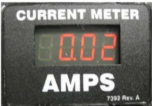
Current Meter Display
Service/Tech Support
Service and Maintenance
No service or maintenance is required. Do not attempt to open the PDU or you may void the warranty. No serviceable parts inside. It is recommended that power be removed from the unit before installing or removing any equipment.
More Technical Support
http://www.geistglobal.com
Email: support@geistglobal.com
Americas
• 1 888 630 4445
Europe and Middle East
• From within the UK 0845 026 3853
• From abroad +44 845 026 3853
Asia
• English +1 888 630 4445 (US number)
• Chinese +86 755 8663 9505
Or contact your distributor.

natural_image
Orange hexagonal logo with abstract geometric shapes (no text or symbols)GEIST
POWER
Thank You For Purchasing Geist
geistglobal.com


- GEIST
- POWER
- Table of Contents
- Introduction 4
- About this Manual 7
- Chapter 1 - Product Specifications 12
- Chapter 2 - Installation 14
- Chapter 3 - Optional Local Metering 24
- Service/Tech Support 25
- Introduction
- Welcome
- Copyrights
- Trademarks
- Use and Disclosure Restrictions
- Recovery Act Buy American
- Trade Agreements Act (TAA)
- Geist Policy on Conflict Minerals
- WEEE Declaration
- Document Usage
- About this Manual
- Organization of the Manual
- Audience Profile
- On-line Documentation
- Reporting Document Errors
- Geist-Documents@geistglobal.com
- Conventions
- Software
- Hardware
- Safety
- DANGER
- WARNING
- CAUTION
- NOTE
- Figures
- Tables
- Chapter 1 - Product Specifications
- Overview
- Environmental
- Temperature
- Humidity
- Elevation
- Electrical
- Receptacle Ratings
- Regulatory Compliance
- Underwriters Laboratories (UL)
- Federal Communications Commission (FCC)
- Chapter 2 - Installation
- Pre-Installation
- Installation
- Mounting
- Full Length Bracket
- Toolless Mounting Hardware (11621)
- Toolless Full Length Bracket (TLFL)
- Adjustable Mount Brackets (AM)
- Panel Mount Brackets (PM)
- 23" Conversion Mounting Brackets (23-RM)
- 19" Horizontal/Panel Mount Brackets (7938)
- Chapter 3 - Optional Local Metering
- Power Meter
- Current Meter
- Service/Tech Support
- Service and Maintenance
- More Technical Support
- Thank You For Purchasing Geist
Brand : Geist
Model : BRDN080-1034TL
Category : Inverter