GVHVRN102-102L13PS6-IP44 - Inverter Geist - Free user manual and instructions
Find the device manual for free GVHVRN102-102L13PS6-IP44 Geist in PDF.

User questions about GVHVRN102-102L13PS6-IP44 Geist
0 question about this device. Answer the ones you know or ask your own.
Ask a new question about this device
Download the instructions for your Inverter in PDF format for free! Find your manual GVHVRN102-102L13PS6-IP44 - Geist and take your electronic device back in hand. On this page are published all the documents necessary for the use of your device. GVHVRN102-102L13PS6-IP44 by Geist.
USER MANUAL GVHVRN102-102L13PS6-IP44 Geist
Installer/User Guide
The information contained in this document is subject to change without notice and may not be suitable for all applications. While every precaution has been taken to ensure the accuracy and completeness of this document, Vertiv assumes no responsibility and disclaims all liability for damages resulting from use of this information or for any errors or omissions. Refer to other local practices or building codes as applicable for the correct methods, tools, and materials to be used in performing procedures not specifically described in this document.
The products covered by this instruction manual are manufactured and/or sold by Vertiv. This document is the property of Vertiv and contains confidential and proprietary information owned by Vertiv. Any copying, use or disclosure of it without the written permission of Vertiv is strictly prohibited.
Names of companies and products are trademarks or registered trademarks of the respective companies. Any questions regarding usage of trademark names should be directed to the original manufacturer.
Technical Support Site
If you encounter any installation or operational issues with your product, check the pertinent section of this manual to see if the issue can be resolved by following outlined procedures. Visit https://www.VertivCo.com/en-us/support/ for additional assistance.
TABLE OF CONTENTS
1 Overview 1
1.1 Environmental 2
1.1.1 Electrical 2
1.1.2 Regulatory Compliance 3
2 Installation 5
2.1 Mounting 6
2.1.1 Optional surge suppression 16
2.1.2 Optional local metering 16
3 Appendices 19
Appendix A: Rack In-line Power Measurement Unit 19
Appendix B: Troubleshooting 21
This page intentionally left blank
1 OVERVIEW
The following rack power distribution units (rPDUs) are covered in this document.
Table 1.1 rPDU Model Series Descriptions
| MODEL | INPUT | INPUT | PLUG TYPE | AC MAIN RATINGS (CURRENT) | AC MAIN RATINGS (VOLTAGE) | OVERCURRENT PROTECTION TYPE (IF APPLICABLE) |
| BR | Single Phase | NEMA Straight Blade, NEMA Twist | Lock 15-20 | AMPS 125V Single Pole Thermal | ||
| NSV | ||||||
| SP | ||||||
| SVR | ||||||
| VRT | ||||||
| VSS | ||||||
| BREVRTE | Single Phase | IEC C20 | 16-20 AMPS | 125V, 250V | Single Pole Thermal of Hydraulic Magnetic | |
| J | SinglePhase/ThreePhase | NEMA Straight Blade, NEMA Twist IEC, Hardwired | Lock 10-20 AMPS | 100-120V | None | |
| MJ | Single Phase | NEMA Straight Blade, NEMA Twist Lock | 15-20 AMPS | 100-120V | None | |
| VHV | SinglePhase/ThreePhase | NEMA Straight Blade, NEMA Twist IEC, IEC Splashproof, Hardwired, Schuko, British | Lock, 10-20 AMPS | 120/208V WYE, 200V, 208-240V | None | |
| BRD | Single Phase | NEMA Twist Lock | 30 AMPS | 125V | Single Pole Thermal | |
| VRE | Single Phase | NEMA Twist Lock | 30 AMPS | 125V, 250V | Single Pole Thermal | |
| VRTD | Single Phase | NEMA Twist Lock | 30 AMPS | 125V | Single Pole Thermal | |
| XP | SinglePhase/ThreePhase | NEMA Straight Blade, NEMA Twist IEC Splashproof | Lock, 30 AMPS | 100-120V, 120/208V WYE, 200V, 208-240V | Hydraulic Magnetic | |
| Y | Three Phase | NEMA Twist Lock, IECPin & Sleeve, Hardwired | 16-32 AMPS | 208-240/360-415V WYE | Hydraulic Magnetic | |
| ZP | SinglePhase/ThreePhase | CS8365, IEC Pin & Sleeve, Hardwired | 35-12 | 100-120V, 120/208V WYE, 200V, 208-240V | Hydraulic Magnetic | |
NOTE: Global Versions of the VHV Series are intended to be connected to a 16 Amp AC M Circuit. Global Versions of the XP Series are intended to be connected to a 32 Amp AC Ma Circuit.
1.1 Environmental
The operational environmental limits pertaining to Temperature, Humidity and Elevation are as defined the following tables.
Table 1.2 Temperature Limits
| MODEL SERIES | OPERATING MINIMUM | OPERATING MAXIMUM | STORAGE MINIMUM | STORAGE MAXIMUM |
| BR, BRE, J, L, NSV, SP, SVR, VHV, VRE, VSS, XP, Y, ZP | VRT, VRTE, 10°C (50°F) 45°C | (113°F) -40°C | (-40°F) 70°C | (158°F) |
| BRD, MJ, VRTD 10°C (50°F) 25°C (77°F) | -40°C (-40°F) 70°C | (158°F) |
Table 1.3 Humidity Limits
| MINIMUM MAXIMUM | ||
| Operating | 5% | 95% (non-condensing) |
| Storage | 5% | 95% (non-condensing) |
Table 1.4 Elevation Limits
| MODEL SERIES | OPERATING MINIMUM | OPERATING MAXIMUM | STORAGE MINIMUM | STORAGE MAXIMUM |
| BR, BRD, BRE, NSV, SP, SVR, VRE, VRT, VRTD, VRTE, VSS | 0 m (0 ft) | 2,000 m (6561 ft) | 0 m | 15,240 m (0 ft)(50,000 ft) |
| J, L, MJ, VHV, XP,Y, ZP |
1.1.1 Electrical
Electrical product characteristics and performance are defined in the following tables. Please see the product nameplate for additional rating limits.
Table 1.5 Receptacle Ratings
| RECEPTACLE TYPE RATINGS | ||
| NEMA 5-15R or L5-15R 12A, 125VAC | ||
| NEMA 5-20R or L5-20R 16A, 125VAC | ||
| NEMA 6-20R or L6-20R 16A, 250 VAC | ||
| NEMA L6-30R 24A, 250VAC | ||
| NEMA L15-20R 3-phase, 16A @ 250VAC | ||
| NEMA L15-30R 3-phase, 24A @ 250VAC | ||
| IEC-60320 C13 10A, 250VAC (UL & CSA 12A, 250VAC | ||
| IEC-60320 C19 16A, 250VAC (UL & CSA 16A, 250VAC |
1.1.2 Regulatory Compliance
Vertiv products are regulated for Safety, Emissions, and Environment Impact per the below agencies policies.
Underwriter Laboratory (UL)
UL Standards are used to assess products; test components, materials, systems and performance; an evaluate environmentally sustainable products, renewable energies, food and water products, recycling systems and other innovative technologies.
The UL standards specific to this equipment (if applicable) are as noted on the device nameplate
Federal Communications Commission (FCC)
The Federal Communications Commission (FCC) regulates interstate and international communications by radio, television, wire, satellite, and cable in all 50 states, the District of Columbia and U.S. territories. An independent U.S. government agency overseen by Congress, the commission is the United States' primary authority for communications laws, regulation and technological innovation.
The FCC standards specific to this equipment are:
This Class A device complies with part 15 of the FCC Rules. Operation is subject to the following conditions: (1) This device may not cause harmful interference, and (2) this device must accept a interference received, including interference that may cause undesired operation.
This Class A digital apparatus complies with Canadian ICES-003.
WARNING! Changes or modifications to this unit not expressly approved by the party responsible for compliance could void the user's authority to operate this equipment.
ROHS/WEEE
RoHS, also known as Lead-Free, stands for Restriction of Hazardous Substances. RoHS, also known Directive 2002/95/EC, originated in the European Union and restricts the use of six hazardous mat found in electrical and electronic products. All applicable products in the EU market after July 1, must pass RoHS compliance. RoHS impacts the entire electronics industry and many electrical products as well.
WEEE stands for Waste from Electrical and Electronic Equipment. WEEE Directive 2002/96/EC mandate the treatment, recovery and recycling of electric and electronic equipment (90% ends up in landfills applicable products in the EU market must pass WEEE compliance and carry the Wheelie Bin stics). See product label for RoHS/WEEE compliance marks.
2 INSTALLATION
Use the following images in the mounting section to install your rack PDU.
NOTE: Please visit http://www.VertivCo.com/ComplianceRegulatoryInfo for important safety information prior to installation.
To install your unit:
- Using appropriate hardware, mount the unit to the rack.
- Plug the rPDU into an appropriately-rated and protected branch-circuit receptacle.
- Plug in the devices to be powered by the rPDU.
- Turn on each device connected to the rPDU.
NOTE: It is recommended that all connected equipment is powered on in a sequential manner high inrush current.
NOTE: XP Series rPDUs may optionally be configured as Isolated Ground units. All Isolated Ground units will be shipped with an enclosure grounding cable. This cable must be connected between enclosure and a reliable safety ground.
2.1 Mounting
Optional mounting brackets are sold separately.
Figure 2.1 Full-length Bracket

text_image
A DETAIL AFigure 2.2 Mini L Bracket

natural_image
Technical line drawing of a mechanical bracket with mounting feet and a separate view of a curved bracket (no text or symbols)DETAIL A

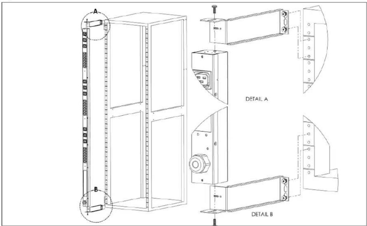
text_image
Technical diagram of a multi-panel cabinet with labeled components A and B, showing internal structure and mounting points.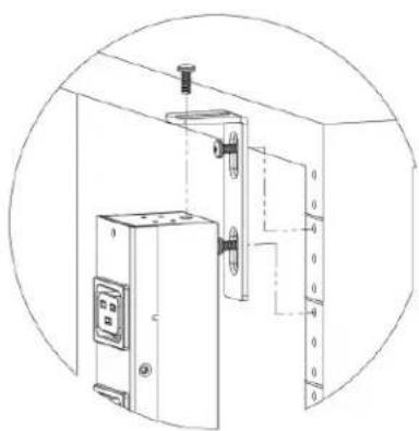
natural_image
Technical line drawing of an electrical cabinet with mounting bracket and control panel (no text or symbols)DETAIL B
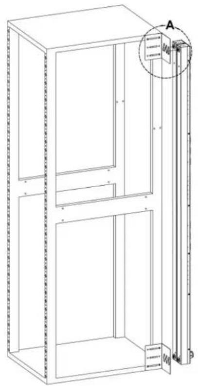
Figure 2.3 Vertical Extension Bracket

text_image
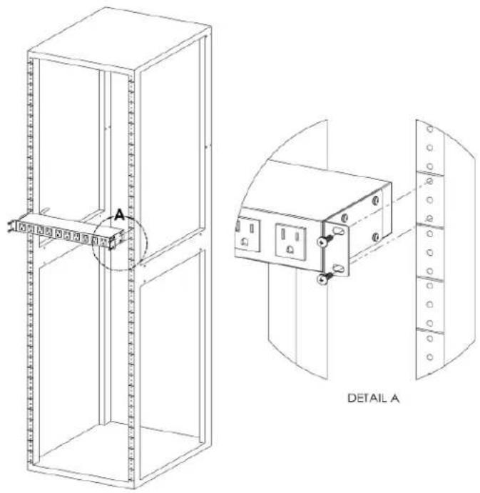
DETAIL A A B DETAIL BFigure 2.4 Tool-less Mounting Hardware
text_image
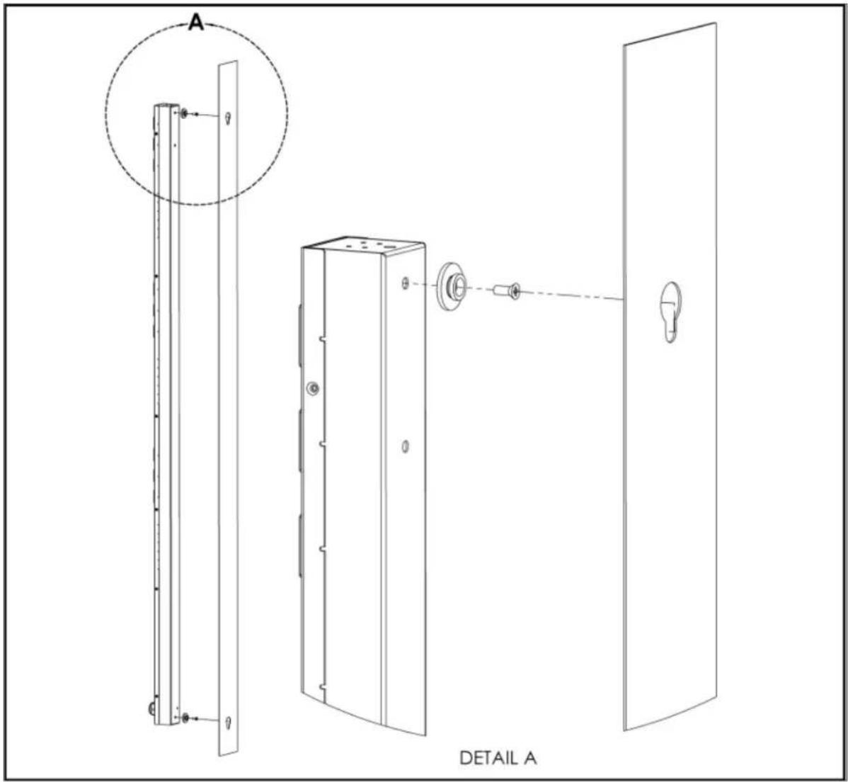
A DETAIL AFigure 2.5 Tool-less Full-length Bracket
text_image
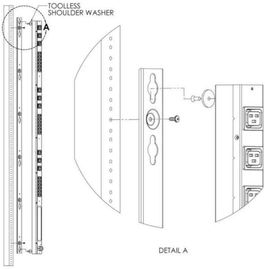
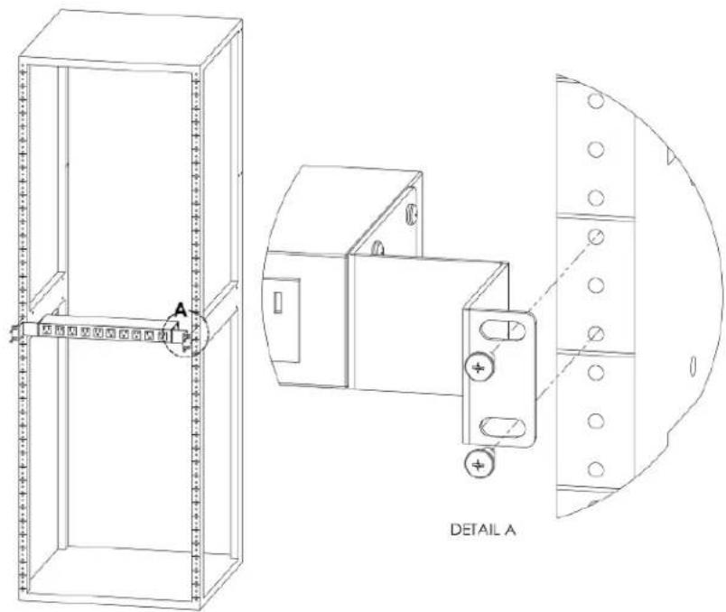
TOOLLESS SHOULDER WASHER A DETAIL AFigure 2.6 Single Side-mount Unit Brackets
natural_image
Technical line drawing of a cabinet or enclosure with internal components and a magnified inset showing a labeled section (A), no text or symbols present.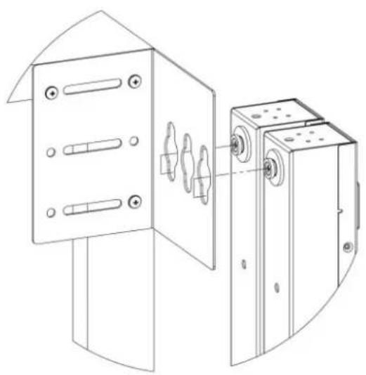
natural_image
Technical line drawing of a mechanical device with two views: one showing internal components and the other showing external housing (no text or symbols)DETAIL A
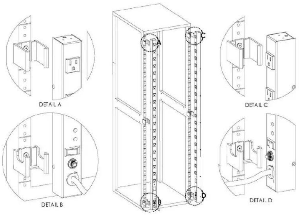
Figure 2.7 Offset Side-mount Brackets

text_image
LEFT SIDE OPTION DETAIL A A B RIGHT SIDE OPTION DETAIL B C DETAIL CFigure 2.8 7" Extension Brackets (XB-7)
text_image
A B DETAIL A DETAIL BFigure 2.9 Flush Mount Brackets (FM)
natural_image
Technical line drawing of a two-panel cabinet with mounting holes and a close-up of its internal components (no text or symbols)Figure 2.10 Adjustable Mount Brackets (AM)

text_image
DETAIL AFigure 2.11 Panel Mount Brackets (PM)

text_image
A DETAIL AFigure 2.12 23" Conversion Mounting Brackets (23-RM)
text_image
内圆型圆锥圆形圆柱 DETAIL AFigure 2.13 19" Horizontal/Panel Mount Brackets (7938)

natural_image
Technical line drawing of a mechanical assembly with two views: top shows a vertical frame with internal components, bottom shows a close-up of a mechanical housing with bolts and a circular detail labeled 'DETAIL A' (no text or symbols on the diagram itself)Figure 2.14 Top and Bottom Mounting Clips (9083C & 9084C)
text_image
DETAIL A DETAIL B DETAIL C DETAIL DNOTE: Mounting clips are only intended for use with NSV and VSS Series rPDUs. Using the bottom mounting clips, attach the rPDU to the rack as shown.
2.1.1 Optional surge suppression
The SP, SVR, and VSS Series rPDUs include a surge suppression circuit that is designed to prevent voltage surges on the input power line from reaching devices powered by the rPDU. The surge suppression circuit uses Metal Oxide Varistors (MOVs) connected between line, neutral, and ground to prevent voltage surges from damaging connected devices.
Figure 2.15 Surge Suppression LEDs

text_image
SURGE POWER ON PROTECTED POWER ON OFF NO RESET 10 PASS 20Table 2.1 Surge Protection Circuit Rating
| NUMBER DESCRIPTION | |
| Protection Modes Line-Line, Line-Neutral, Neutral-Ground | |
| Maximum Clamping Voltage 340V | |
| Energy Absorption 720 Joules | |
| Green Light Indicator Power On | |
| Red Light Indicator Surge Protection Active |
2.1.2 Optional local metering
Power meter
The Geist PM-1 power meter is a low-power, high accuracy meter capable of measuring true RMS Voltage, Power, and Power Factor. These values are individually shown on a 4-digit LED Display, continuously scrolls through the four different measured values. Each one of these displayed parameters is defined below. The power meter automatically cycles through the displayed values when the rPC connected to AC Mains power.
- Current: rPDU output current draw measured in true RMS Amps.
• Voltage: rPDU output voltage measured in true RMS Voltage.
• Power: rPDU output power measured in Watts – referred to as real or active power.
• Power Factor: Ratio of real rPDU output power to apparent rPDU output power.
Figure 2.16 Power Meter Display
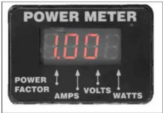
text_image
POWER METER 1.00Ω POWER FACTOR AMPS VOLTS WATTSCurrent meter
The Geist CM-1 current meter is a low-power, high accuracy meter capable of measuring true RM Current. The value of current is continuously shown on a 4-digit LED Display. The Current Meter automatically displays the value of output current when the rPDU is connected to AC Mains power
Figure 2.17 Current Meter

text_image
CURRENT METER 0.02 AMPS 7392 Rev. AThis page intentionally left blank
3 APPENDICES
Appendix A: Rack In-line Power Measurement Unit
A.1 Product Specifications
Basic rack PDUs not equipped with local current monitoring can be retrofit with L-Series inline pc monitoring units. The L-series products are inline power monitoring units intended for connection between an AC Mains circuit and a Rack Power Distribution Unit (rPDU). The inline power monitor units are designed to be powered by a single phase AC input circuit and have an outlet or on and connector body for connection to an external device (such as an rPDU). The Inline power n units are rated from 12 to 32 Amps depending on the unit's configuration. Inline power monitoring can be configured with a Geist local current meter or power meter to perform the monitoring fu
Table A.1 L-Series Inline Power Monitoring Units
| PART # | MODEL # | AMPS VOLTS | PLUG TYPE | RECEPTACLE TYPE | |
| 12416 | GLCE-001C13-00C14 | 10 | 230 | IEC C14 | IEC C13 |
| G1113 | GLCE-002C19-00C20 | 16 | 230 | IEC C20 | IEC C19 |
| 15693 | LCE-001C13-00C14 | 15 | 125 or 208 | IEC C14 | IEC C13 |
| 15694 | LCE-002C19-00C20 | 20 | 125 or 208 | IEC C20 | IEC C19 |
Figure A.1 L-Series Inline Power Monitoring Unit

text_image
POWER METER POWER FACTOR AMPS VOLTS WATTSA.2 Detachable power supply cords
L-Series Inline Power Monitoring Units may optionally be configured with an AC Inlet for connectio Mains power. Use only detachable power supply cords of the appropriate size and type, as stated with the unit. Use only with light PVC sheathed flexible cords (according to IEC 60227) or ordin rubber-sheathed flexible cords (according to IEC 60245) that terminate in an attachment plug meeti local/national code requirements.
For Global units use a minimum 1.5 mm2 nominal conductor cross-sectional area detachable power cord with ratings of 300 V and 75 °C. The power supply cord cable designation should be H03H03VVH2-F, or better.
For North American units use a minimum 14 AWG power supply cord with ratings of 300 V an power supply cord cable designation should be SJT or better.
To install an L-Series inline power monitoring unit:
NOTE: Please visit http://www.VertivCo.com/ComplianceRegulatoryInfo for important safety information prior to installation.
- Using the appropriate hardware, mount the In-Line Meter to the rack.
- Plug the In-Line Meter into de-energized branch circuit receptacle.
- Connect the external device to the In-Line Meter's output outlet or connector.
- Turn on the branch circuit to energize the In-Line Meter.
- Power on the external device.
NOTE: Branch Circuit should be sized based on the In-Line Meter's nameplate electrical rating. North American units, the branch circuit should have a current rating equal to 125% of the nameplate current rating. For global units, the branch circuit should have a current rating equal to unit's nameplate current rating.
Appendix B: Troubleshooting
Ensure all devices plugged in to the rack PDU receptacles are receiving power.
No service or maintenance is required. Do not attempt to open the rPDU or you may void the There are no serviceable parts inside the rPDU. It is recommended that power be removed from before installing or removing any equipment.
B.1 Technical Support
Technical support can be found at www.VertivCo.com/support.
Americas
• Website: www.VertivCo.com/geist
- Email: support@VertivCo.com
• Telephone: 1-888-630-4445
Europe and Middle East
• Technical Support: www.VertivCo.com/en-emea/support
- Email: eoc@VertivCo.com
• Telephone: 1-800-1155-4499
Asia
• Telephone (English): 1-888-630-4445 (US number)
• Telephone (Chinese): +86 755 8663 9505
This page intentionally left blank

VERTIV™

VERTIV™