
FS3-3013 - Toilets PolyJohn - Free user manual and instructions
Find the device manual for free FS3-3013 PolyJohn in PDF.

| Product Type | Portable Restroom |
| Model | FS3-3013 |
| Brand | PolyJohn |
| Exterior Height | 91 in (231 cm) |
| Interior Height | 83 in (211 cm) |
| Exterior Width | 47 in (119 cm) |
| Interior Width | 45.7 in (116 cm) |
| Exterior Length (Runner Base) | 48 in (122 cm) |
| Exterior Length (Optional Handle Base) | 47 in (119 cm) |
| Interior Length | 43 in (109 cm) |
| Weight (Flush) | 243 lb (110 kg) |
| Door Frame Height (ID) | 75 in (191 cm) |
| Door Frame Width (ID) | 26 in (66 cm) |
| Seat Height | 19.5 in (49.5 cm) |
| Fresh Water Tank Capacity | 20 gal (75.7 L) |
| Waste Tank Capacity (Non-Flush) | 55 gal (208 L) after 5 gal charge |
| Waste Tank Capacity (Flush) | 35 gal (132 L) after 5 gal charge |
| Flush Type | Fresh water or recirculating (switchable) |
| Construction Materials | Plastic panels, aluminum extrusions |
| Optional Lock | Yes, exterior key lock |
| Cleaning | Mild soap; acrylic mirror use plastic cleaner |
| Warranty / Support | Contact PolyJohn: 800-292-1305 |
Frequently Asked Questions - FS3-3013 PolyJohn
User questions about FS3-3013 PolyJohn
0 question about this device. Answer the ones you know or ask your own.
Ask a new question about this device
Download the instructions for your Toilets in PDF format for free! Find your manual FS3-3013 - PolyJohn and take your electronic device back in hand. On this page are published all the documents necessary for the use of your device. FS3-3013 by PolyJohn.
USER MANUAL FS3-3013 PolyJohn
natural_image
Line drawing of a modular electronic device with front panel and side legs (no text or symbols)SPECIFICATIONS
DIMENSION
IMPERIAL
METRIC
Exterior Height 91 in 231 cm
Interior Height 83 in 211 cm
Exterior Width 47 in 119 cm
Interior Width 45.7 in 116 cm
Exterior Length (Runner Base) 48 in 122 cm
Exterior Length (Optional
Signature Style Handle Base) 47 in 119 cm
Interior Length 43 in 109 cm
Weight - Flush 243 lb. 110 kg
Door Frame Height (ID) 75 in 191 cm
Door Frame Width (ID) 26 in 66 cm
Side Panel Decal Area 6 in X 37 in 15 cm X 94 cm
Door Decal Area 22.5 in X 29 in 57 cm X 74 cm
Seat Height
19.5 in 49.5 cm
POLYJOHN
USA
PolyJohn Enterprises Corp.
2500 Gaspar Ave.
Whiting, IN 46394
Phone: 800-292-1305
Fax: 219-659-0625
www.polyjohn.com
info@polyjohn.com
POLYJOHN
WORLDWIDE
PolyJohn (UK) Ltd.
Equinox 1 Audby Lane
Wetherby, England LS22 7RD
Phone: 44 (0) 1937-583333
Fax: 44 (0) 1937-583322
www.polyjohn.co.uk
sales@polyjohn.co.uk
POLYJOHN
CANADA
PolyJohn Canada
P.O. Box 2300
199 Forest Plain Rd.
Orillia, Ontario LV3 6S2
Phone: 800-465-9590
Fax: 705-325-8250
www.polyjohncanada.ca
info@polyjohncanada.ca
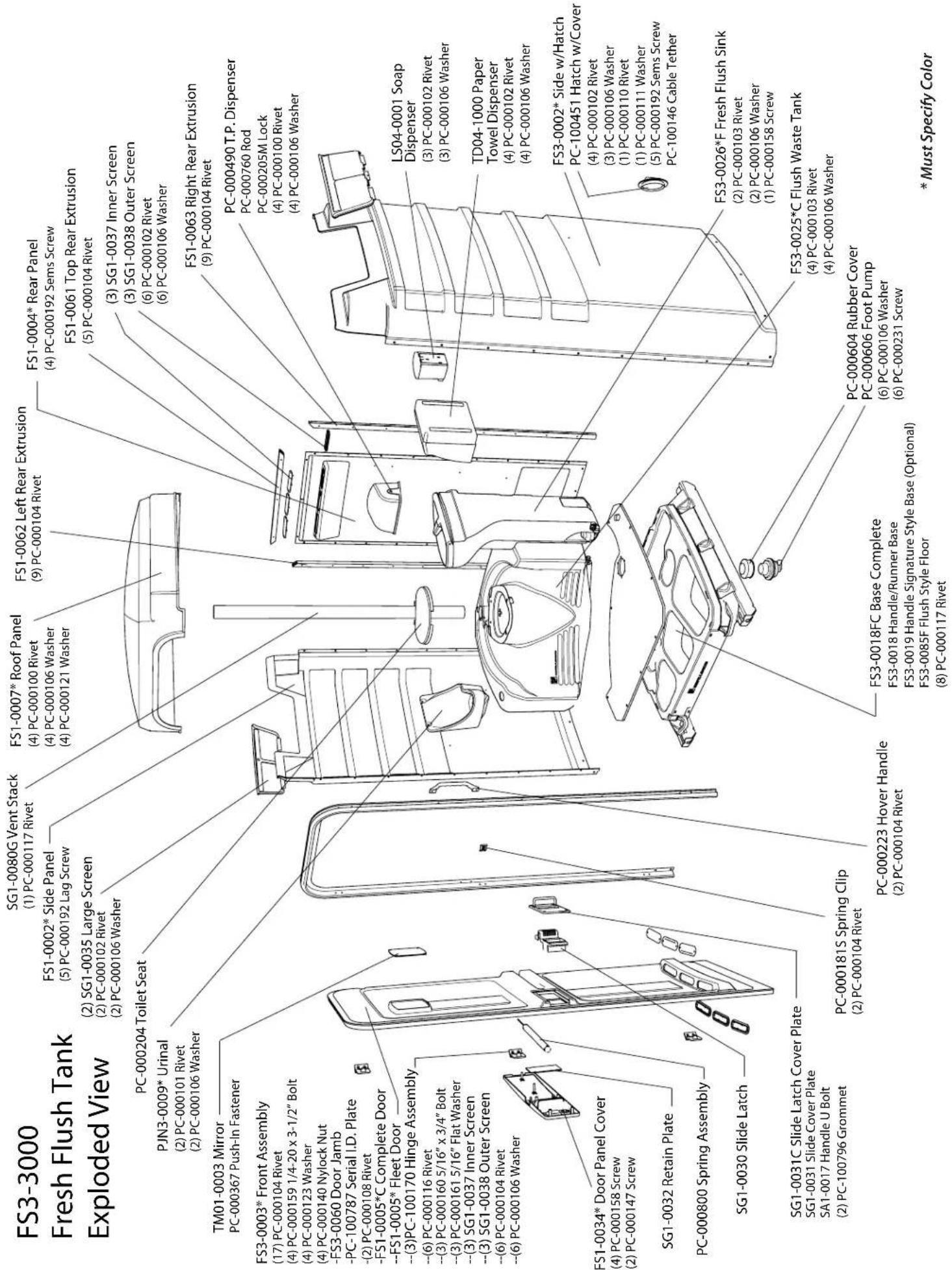
FS3-0025C Parts Listing
GENERAL OVERVIEW
•These instructions are for restrooms shipped unassembled. Please retain these instructions for maintenance and repair purposes.
•The FS3-3 Model restroom assembly will require two people.
- All references to left, right, front and rear are as viewed from the front of the restroom.
- Review the entire instruction manual prior to assembly.
- Please follow the instructions in the order they are presented.
- When using air operated screw drivers or impact wrenches, be sure that the torque setting does not exceed 28 inch pounds. Also, when using a battery-operated drill, set it to the lowest torque setting.
•We strongly suggest that these restrooms, as with all portable structures, be transported and handled with care. Dropping the restroom when loading and unloading could cause damage to the door jamb and other components.
\~\~TOOLS REQUIRED FOR ASSEMBLY!\~\~
• Rivet Gun
• Standard Slotted Screwdriver
• Phillips Crosshead Screwdriver
• Vise-Grips
• Pliers
• (2) Tapered Awls • Drill with a 13/64" Drill Bit • Socket Wrench with a 7/16" socket
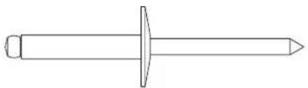
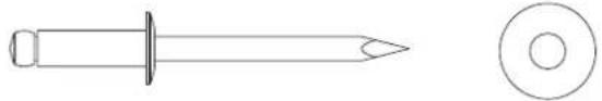
FULL SCALE FASTENER DRAWINGS
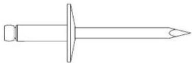
natural_image
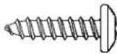
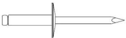
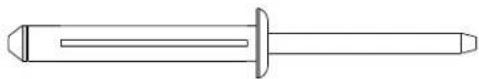
Line drawing of a screw with a pointed tip and threaded head (no text or symbols)(8) PC-000100 - Rivet
natural_image
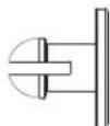
Line drawing of a mechanical screw or fastener with a central pin and flange (no text or symbols)(2) PC-000101 - Rivet
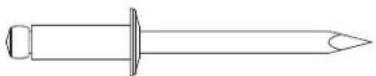
(9) PC-000102 - Rivet
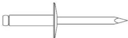
natural_image
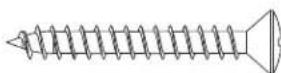
Simple line drawing of a nail with a pointed tip and circular head (no text or symbols)(6) PC-000103 - Rivet

(42) PC-000104 - Rivet
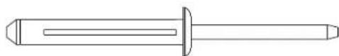
(1) PC-000117 - Rivet

(4) PC-000140 Lock Nut

(31) PC-000106 - Washer

(4) PC-000123 - Washer

natural_image
Simple geometric diagram of a circle divided into two smaller inner circles (no text or symbols)(4) PC-000121 - Washer
(4) PC-000367 - Nylon Push-In Fastener
(2) PC-000147 3/4" Phillips Self Tapping Screw
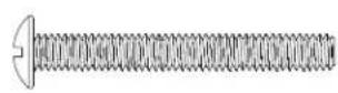
(5) PC-000158
1-1/2" Phillips Self
Tapping Screw
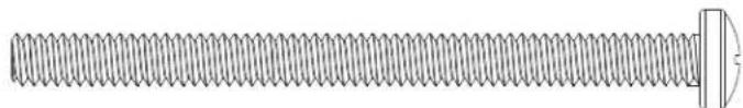
(6) PC-000231
10-32 x 1-1/2" Screw
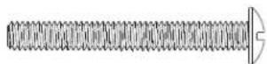
natural_image
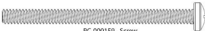
Technical line drawing of a threaded screw with a flat end (no text or symbols)(4) PC-000159 - Screw
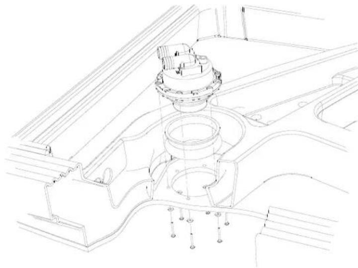
Step 1: Pump Installation
natural_image
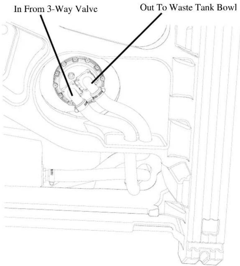
Technical line drawing of a mechanical assembly with no visible text or symbolsPlace the PC-000604 rubber dust cover over the top of the pump and from the underside of the base, place the pump up into the hole in the floor. Line up the holes in the floor with the threaded inserts in the pump making sure that the barbed fittings of the pump point toward the holes drilled in the base (as shown on the left). Finish installation of the pump by tightening in place using (6) PC-000231 screws with (6) PC-000106 washers behind the heads of the screws.
PC-000231 Screw (6) Used in this step

PC-000106 Washer (6) Used in this step
Step 2: Tank-Sink Installation
Place the tank into the opening of the base. Locate the 1" reinforced hose coming out of the hole at the back of the waste tank. Pull about 3 feet of this hose out of the hole and route this hose down through the opening in-between the waste tank and the base. Place the sink on the base, lining up the 1/2" drain pipe, inserting into the corresponding hole in the tank. Insert the ends of the two hoses into the slot, reaching underneath the base to pull out the slack.
Step 3: Sidewall Panels to Rear Extrusions and Rear Wall Panel
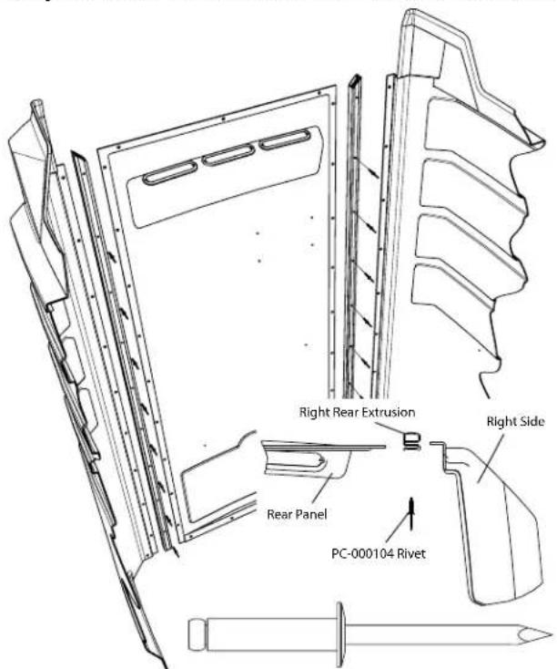
PC-000104 Rivet (16) Used in this step

natural_image
Technical line drawing of a mechanical device with no visible text or symbolsSlide a plastic rear extrusion onto each side of the rear panel making sure that the mitered ends are towards the top of the rear panel (where the fly screens are, and the ribbed side of the extrusions are facing toward the outside of the restroom). Line up the holes in the rear extrusions with the holes in the rear wall panels. Insert awls into the center holes. Slide the right side wall panel (with hatch in corner) into the corresponding slot of the rear extrusion and remove the awl from that rear extrusion. Line up all of the holes and rivet from the inside, the rear extrusions, rear wall panel and side wall panel together using small flange, rivets, PC-000104. DO NOT RIVET THE TOP HOLE IN EITHER OF THE EXTRUSIONS AT THIS TIME. Remove the awl in the left extrusion and rivet together the left side wall panel, left rear extrusion, and rear panel, leaving the top hole for later.
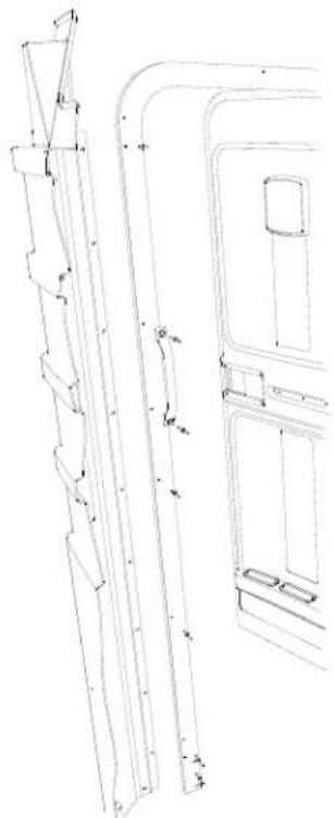
Step 4: Sidewall Panels to Door Jamb
Insert the edge of the left side panel into the slot on the left side of the door jamb. Line up the holes in the jamb with the corresponding holes in the side panel. Rivet the second and third holes from the bottom as well as the top two holes using (4) PC-000104 rivets (as shown on the left). Using holes in the jamb as a guide, drill three 13/64" holes into the side panel. Rivet the PC-000181 cable clip at the center two holes of the jamb using (2) PC-000104
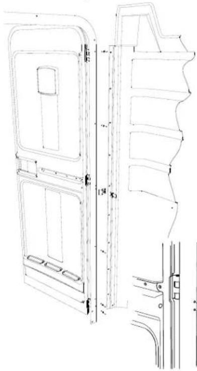
natural_image
Technical line drawing of a door frame structure with mounting brackets and side panels (no text or symbols)rivets. Rivet the bottom hole using the same rivet. Wrap the cabana around the base of the unit resting the bottom edge of the sides on the ledge around the base. Slide the edge of the right side wall panel into the slot in the jamb. Line up the holes in the side panel with the corresponding holes in the jamb and rivet in place using (4) PC-000104 rivets. DO NOT RIVET THE SECOND HOLE FROM THE TOP AT THIS TIME. Using a drill with a 13/64" drill bit, drill out the third hole from the top as well as the bottom hole. Rivet the bottom hole using a PC-000104 rivet. The PC-000223 grab handle gets attached to the jamb using (2) PC-000104 rivets at the second and third hole locations.

PC-000104 Rivet
(14) Used in this step
natural_image
Technical line drawing of a mechanical assembly with no visible text or symbolsStep 5: Cabana to Base
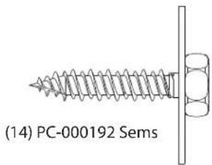
Insert (4) PC-000159 bolts through the holes at the bottom of the jamb and into the slots in the base. On the back-side of the unit, center the rear panel on the base and fasten to the base using (4) PC-000192 sems. Gently lay the unit on it's back. Place (4) PC-000123 washers and (4) PC-000140 nuts on the PC-000159 bolts at the front of the base. DO NOT TIGHTEN AT THIS TIME. Close the door and tighten the bottom bolts (making sure that there is a 1/4" gap between the latch side of the door and the jamb). Open the door and tighten the top bolts.
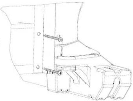
natural_image
Technical line drawing of a mechanical assembly with bolts and brackets (no text or symbols)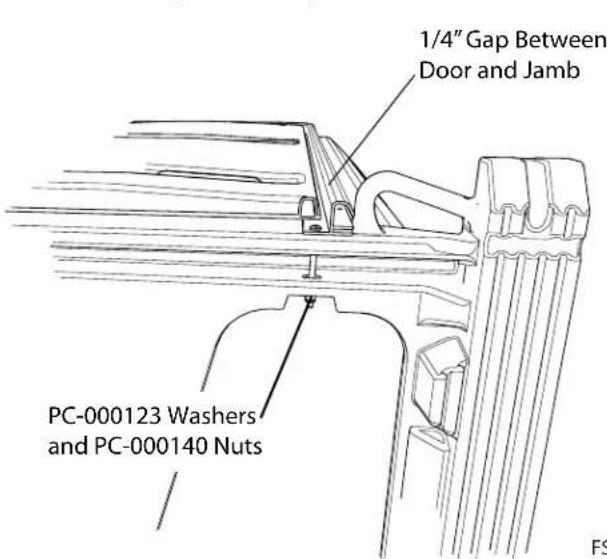

PC-000123 - Washer
(4) Used in this step

PC-000140 Lock Nut
(4) Used in this step

(4) Used in this step
natural_image
Technical illustration of a screw with threaded shaft and mounting bracket (no text or symbols)PC-000159 - Screw
(4) Used in this step
Step 6: Hose Connections
Route the hose coming from the rear of the waste tank through the 1-3/8" dia. hole in the base, (located closest to the right-hand side of the base). Place a PC-000352 hose clamp on the end of the hose and push the end of this hose onto the discharge side of the pump. Tighten the clamp. Place a PC-000352 hose clamp on the end of the hose coming from the right-hand side of the slot in the floor. Push the end of this hose on the fitting at the bottom of the waste tank, and tighten the clamp. Route the remaining hose over the other hoses and through the 1-3/8" hole in the base. Place a PC-000352 hose clamp on the end of the hose, push the hose onto the intake side of the pump, and tighten the hose clamp.
Step 7: Cabana to Base (Continued)
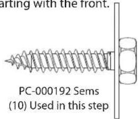
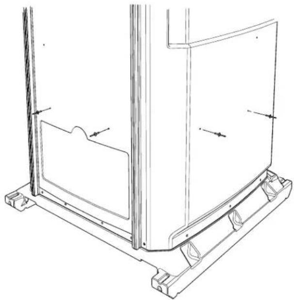
Carefully stand the unit upright. Starting with the left of the unit, drive a PC-000192 sems screw through the pre-drilled hole in the front of the side panel. BE SURE NOT TO OVERTIGHTEN AND STRIP OUT THE PLASTIC. Continue around the left side of the unit, until you reach the rear extrusion. Repeat this process with the right side of the unit, starting with the front.
Step 8: Tank Installation
On the inside of the unit, pull the tank forward in the opening of the floor. Locate the dimples in the lower portion of the rear and left wall panels. Drill four 13/64" holes through the dimples and into the back of the tank. Rivet from outside the restroom using (4) PC-000103 rivets with (4) PC-000106 back-up washers on the inside of the tank.
natural_image
Simple line drawing of a nail screw with a pointed tip and circular head (no text or symbols)PC-000103 Rivet
(4) Used in this step

PC-000106 Washer
(4) Used in this step
natural_image
Technical line drawing of a mechanical assembly with mounting brackets and structural elements (no text or symbols)Step 9: Sink Installation
Locate the dimples located on the middle portion of the rear and the right wall panels. Using a drill with a 13/64" drill bit, drill two holes through the side/rear and into the sink. Open up the sink. To unlock the sink, insert a long thin object (the key for the lock on the T.P. Dispenser works well) into the 1/4" hole directly below the bottom of the sink lid, and while pushing down on the front of the lid of the sink, push the (key) in to release the catch, and lift up the lid. Rivet in place using (2) PC-000103 rivets with (2) PC-000106 washers on the inside of the sink. Fasten the bottom of the sink in by driving a PC-000158 screw through the hole in the aluminum foot pump plate and into the floor plate of the base.
natural_image
Technical line drawing of a mechanical assembly with mounting brackets and structural supports (no text or symbols)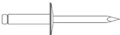
natural_image
Simple line drawing of a screw with a pointed tip and circular head (no text or symbols)PC-000103 Rivet
(2) Used in this step

PC-000106 Washer
(2) Used in this step

PC-000158 Screw
(1) Used in this step
Step 10: Screen Installation
Take a SG1-0035 large fly screen and place the bottom curved fl anges onto the top of the right side panel (as shown on the right). Tilt the top of the fly screen up into place. Using the hole in the bottom, middle fl ange as a guide, drill a 13/64" hole through the side panel. Rivet in place using a PC-000102 rivet from the inside with a PC-000106 back-up washer on the outside. Repeat this step with the left side.
natural_image
Technical line drawing of a screw and a washer (no text or symbols)PC-000102 Rivet
(2) Used in this step
PC-000106 Washer
(2) Used in this step

natural_image
Technical line drawing of a mechanical assembly with no visible text or symbolsStep 11: Roof Installation
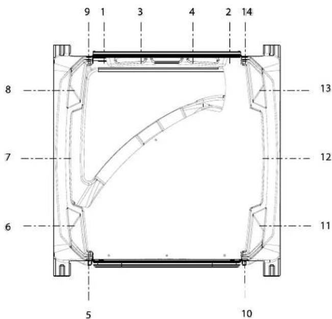
Place the FS1-0061 top extrusion on the top edge of the rear panel so that the miters line up with the left and right extrusions, and that the grooved surface is facing the outside. Place the roof on the top of the unit with the arch in the roof going into the groove in the top of the jamb. Put the rear edge of the roof in the groove in the top rear extrusion. With someone pushing down on the back of the roof, use the holes in the rear extrusion as a drill guide, drill five 13/64" holes into the roof. MAKE SURE TO ONLY DRILL THROUGH THE ROOF AND NOT THROUGH THE BACK OF THE TOP REAR EXTRUSION. Rivet the top holes in both the left and right rear extrusions as well as the fi ve holes of the top rear extrusion using (7) PC-000104 rivets. Push down on the front of the roof while using the holes in the jamb as a drill guide, drill five 13/64" holes through the roof. Rivet in place using (5) PC-000104 rivets. Locate the holes in the top of each of the side panels. Push out on the top of the side panel, and using a 13/64" drill bit, drill a hole through the hole in the top of the side, and through the roof. Rivet in place using a PC-000100 rivet on the inside with a PC-000121 washer and a PC-000106 back-up washer on the topside of the roof. Repeat for remaining three holes.
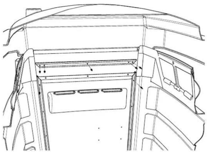
natural_image
Technical line drawing of a vehicle interior frame with structural ribs and doorways (no text or symbols)
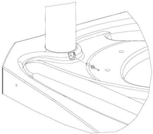
Step 12: Vent Stack Installation
Force the vent stack up through hole in roof then down into the corresponding hole in the tank. Drill a 13/64" hole through the boss in the tank and into the vent stack. Rivet (as shown) using a PC-000117 rivet.
PC-000117 Rivet (1) Used in this step
natural_image
Technical line drawing of a mechanical component with no visible text or symbolsStep 13: Spring Installation
From the front of the door, insert the cable end of the spring assembly into the 1/2" hole in the door. Make sure that the 1/2" boss in the end cap of the spring assembly is pushed through the hole. On the inside of the unit, place the top of a hammer against the PC-000181S spring cable clip (as shown on the right). Place the end of the spring cable in the claw of the hammer.
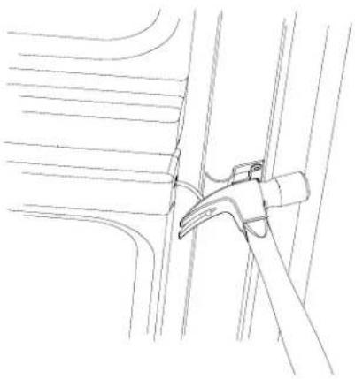
natural_image
Line drawing of a mechanical clamp securing a bracket (no text or symbols)
natural_image
Technical line drawing of a mechanical assembly with no visible text or symbolsOpen the door while holding the hammer in position. Hold the door open with your foot, and clamp a vice-grips pliers on the cable where it comes out of the door. BE SURE TO CLAMP DOWN TIGHT. Remove the cable from the claw of the hammer, close the door, and place the end of the cable into the slot of the cable clip. Open the door, and remove the vice-grips.
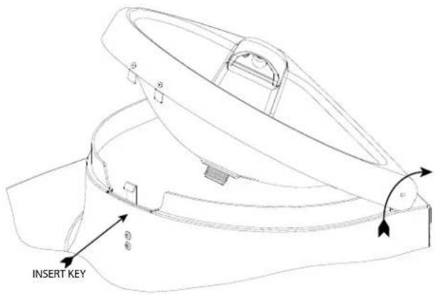
Step 14: Optional Lock Installation
Place the tip of a screwdriver in the lock area of the Door Trim Panel (as shown on the right). Strike the handle end of the screwdriver with a hammer to "knockout" the plastic filling the hole for the lock. Remove the nut from the end of the lock, and insert the lock through the hole of the Door Trim Panel from the outside. Re-insert the nut back on the lock and tighten down. Insert the key and turn the lock to the right and remove the key (this is the locked position which is needed at this point to check the lock for proper installation with the Slide Latch mechanism which is installed in the next step). NOTE: Turning the key upright is the neutral or normal use position which allows the Slide Latch to move into the "Open/In-Use" position when persons are inside the restroom. Turning the key to the left is the open position and the key can not be removed until either in the "Open/In-Use" or "Locked" position.

natural_image
Technical line drawing of a hammer and screwdriver installing or adjusting a component on a tray (no text or symbols)Step 15: Door Panel /Slide Latch Installation
Snap the Unisex Indicator Plate into the back of the Door Trim Panel. Place the Door Trim Panel into the recess in the front of the door. While holding the Door Trim Panel in position, place the Slide Latch and Slide Latch Cover Plate on the inside of the door and line up the holes of the Slide Latch Cover Plate, the Door, and the Door Trim Panel. Insert (4) PC-000158 screws and tighten. NOTE: These screws should be tightened to the point where they will interfere with the sliding action of the Slide Latch and then backed off slightly, leaving enough friction to prevent the Slide Latch from sliding into the "In-Use/Open" position when the door shuts. The U Shaped handle prevents persons from inadvertently moving the slide latch to the "In-Use" position when exiting the restroom. Insert the flip "Male-Female" Indicator Plate into the slot on the top edge of the Door Trim Panel (above where the Unisex Indicator Plate is located). Insert (2) PC-000147 screws into the holes toward the hinged side of the door, line up with the holes in the Door Trim Panel, and tighten. If the optional lock is installed, unlock the lock by inserting the key into the lock and turning to the left and back to the upright position which is the neutral or normal use position and remove the key (this allows the Slide Latch to move into the "Open/In-Use" position when persons are inside the restroom). Turn the key to the right and remove the key for the locked position. Turning the key to the left indicates the open position and the key can not be removed until either in the "Open/In-Use" or "Locked" positon. IMPORTANT: The punched 1/4" hole in the center of the Slide Latch where the "In-Use/Open" stamp is imprinted complies with code enabling the door to be unlocked from outside the restroom in the event of distress and a person inside were unable to unlock the door. A POINTED OBJECT INSERTED INTO THE HOLE AND MOVING THE SLIDE LATCH TO THE LEFT WILL ALLOW THE DOOR TO BE OPENED PROVIDING THE DOOR HAS NOT BEEN LOCKED WITH THE KEY.
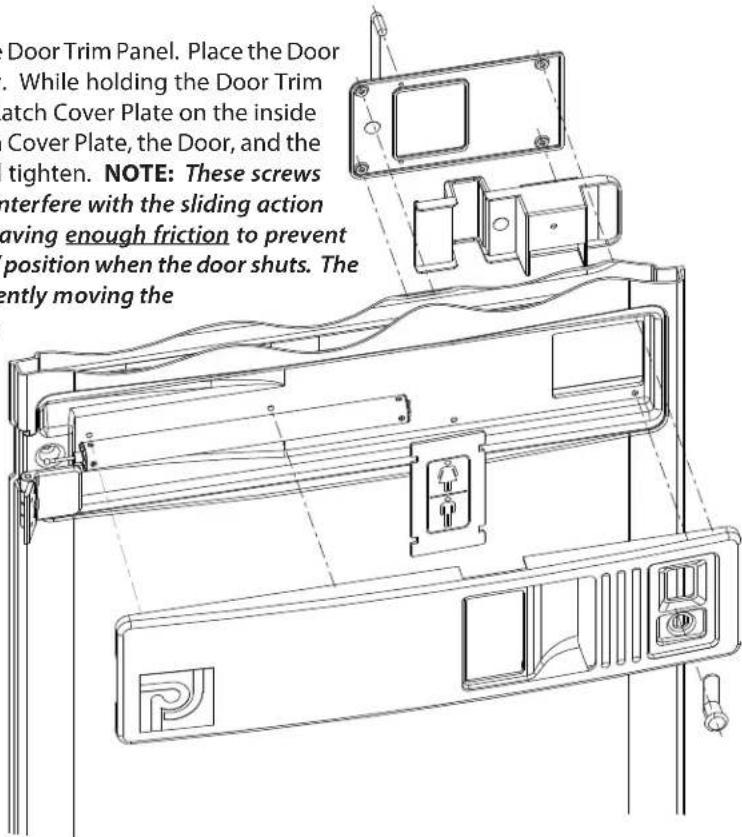

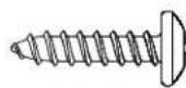
PC-000158 Screw (4) Used in this step
PC-000147 Screw (2) Used in this step
Step 16: Mirror Installation
Peel the protective cover from the front of the mirror. Place the mirror in the recess in the door, and fasten in place using the plastic push-in fasteners provided.
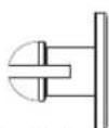
PC-000367 - Push-In Fastener
(4) Used in this step
Step 17: Toilet Seat Installation
Place the toilet seat on the top of the tank. Line up the holes in the hinge of the seat with the holes in the top of the tank. Insert the seat bolts through the hinges of the seat and through the seat base. Lift open the seat base, thread the plastic seat nuts on the ends of the bolts and tighten.
Step 18: Optional Urinal Installation
Insert the drain spigot into the hole in the tank (as shown). Make sure that the top of the urinal is level and drill two 13/64" holes in the center of each of the recess' through the top of the urinal and through the side panel. Rivet in place using (2) PC-000101 rivets from the inside of the unit with (2) PC-000106 back-up washers on the outside.

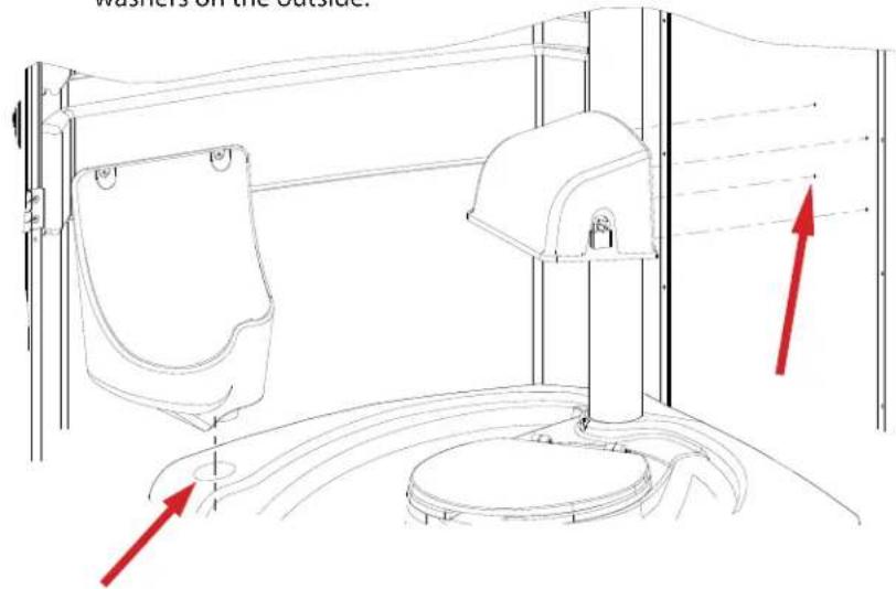

PC-000106 Washer
(4) Used in this step
Step 19: Toilet Paper Dispenser
There are four dimples in the rear panel for the Toilet Paper Dispenser location. From the outside, drill four 13/64" holes through the rear panel. Line up the holes in the rear panel with the holes in the back of the dispenser, and rivet in place from the outside using (4) PC-000100 rivets with (4) PC-000106 back-washers on the inside.
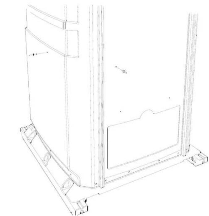
Step 20: Soap and Paper Towel Dispenser
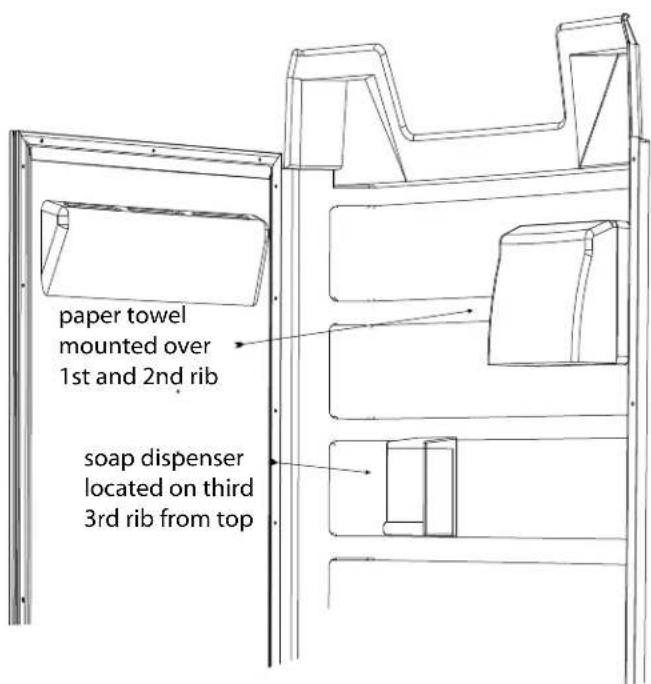
Remove the lid of the Soap Dispenser by pressing up on the tabs of the lid. Remove the backing plate from the dispenser by pushing back on the tab at the top, and sliding the backing plate down. Place the backing plate up against the side wall on the third rib down from the top. Line up the bottom of the backing plate with the bottom of the rib, and using the top of the three mounting holes as a guide, drill three 13/64" holes through the side panel. Rivet in place from the outside using (3) PC-000102 rivets with (3) PC-000106 back-up washers on the inside. Place the body of the soap dispenser on the backing plate, and snap the top back on. Open up the Paper Towel Dispenser. Place the dispenser on the top and second ribs as shown to the right. Using the mounting holes as a drill guide, drill four 13/64" holes through the side panel. Rivet in place using (4) PC-000102 rivets from the outside with (4) PC-000106 back-up washers on the inside.
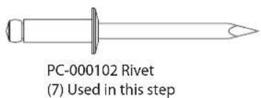
PC-000106 Washer (7) Used in this step
GENERAL USE AND MAINTENANCE
Opening The Sink
The sink holds the fresh water for hand wash as well as for the fresh water flushing operation of the waste tank. The lid of the sink is hinged and locked with a keyless lock for ease of accessibility. To unlock the sink, insert a long thin object (the key for the lock on the T.P. Dispenser works well) into the 1/4" hole directly below the bottom of the sink lid, and while pushing down on the front of the lid of the sink, push the (key) in to release the catch, and lift up the lid.

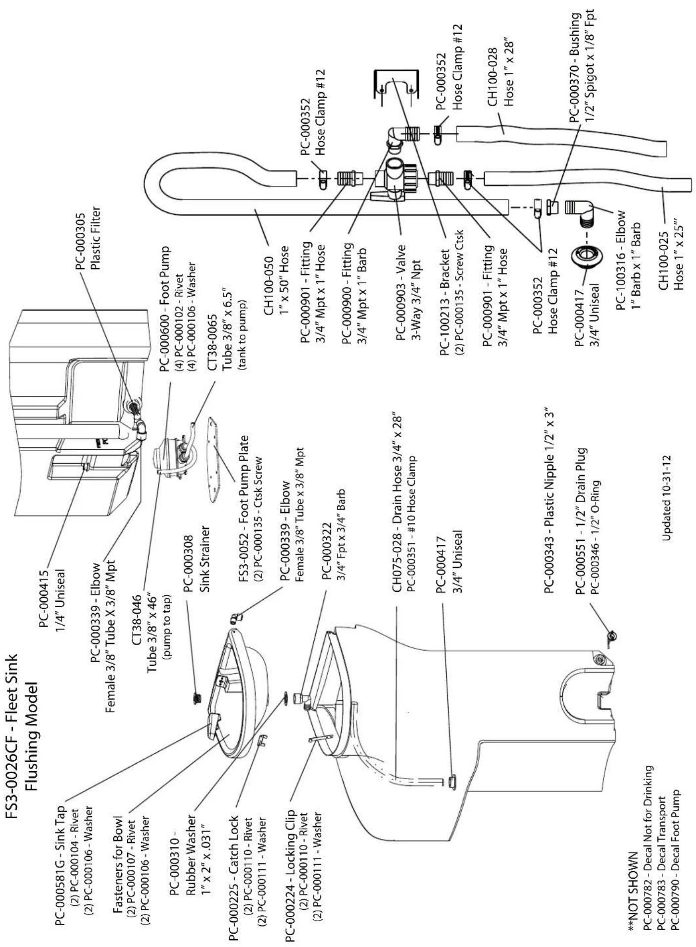
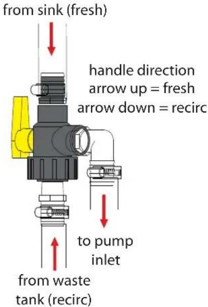
Switching from Fresh Water Flush to Recirculating Flush / Recirculating Flush to Fresh Flush modes
This unit can be converted from fresh water flush to recirculating flush with just a flip of the lever on the 3-way valve. The 3-way valve is located in the right rear corner of the unit, in the back of the sink. The hatch in the corner protects the valve from being tampered with. To change from fresh flush to recirculating mode, and vice versa, open the hatch, and turn the yellow handle of the valve in the opposite direction of where it currently is. The unit is in fresh water flush mode when the handle is pointing up, and is in recirculating mode when the handle is pointing down. Replace the hatch when completed.
Locking/Unlocking the Unit (Optional)
If this unit is equipped with an optional exterior lock, it can be locked to prevent unwanted usage in the evening or weekend hours when no one is on site. This is done by turning the lock to the right and removing the key. When it comes time to unlock the unit, insert the key and turn all the way to the left, and then back to the upright position.
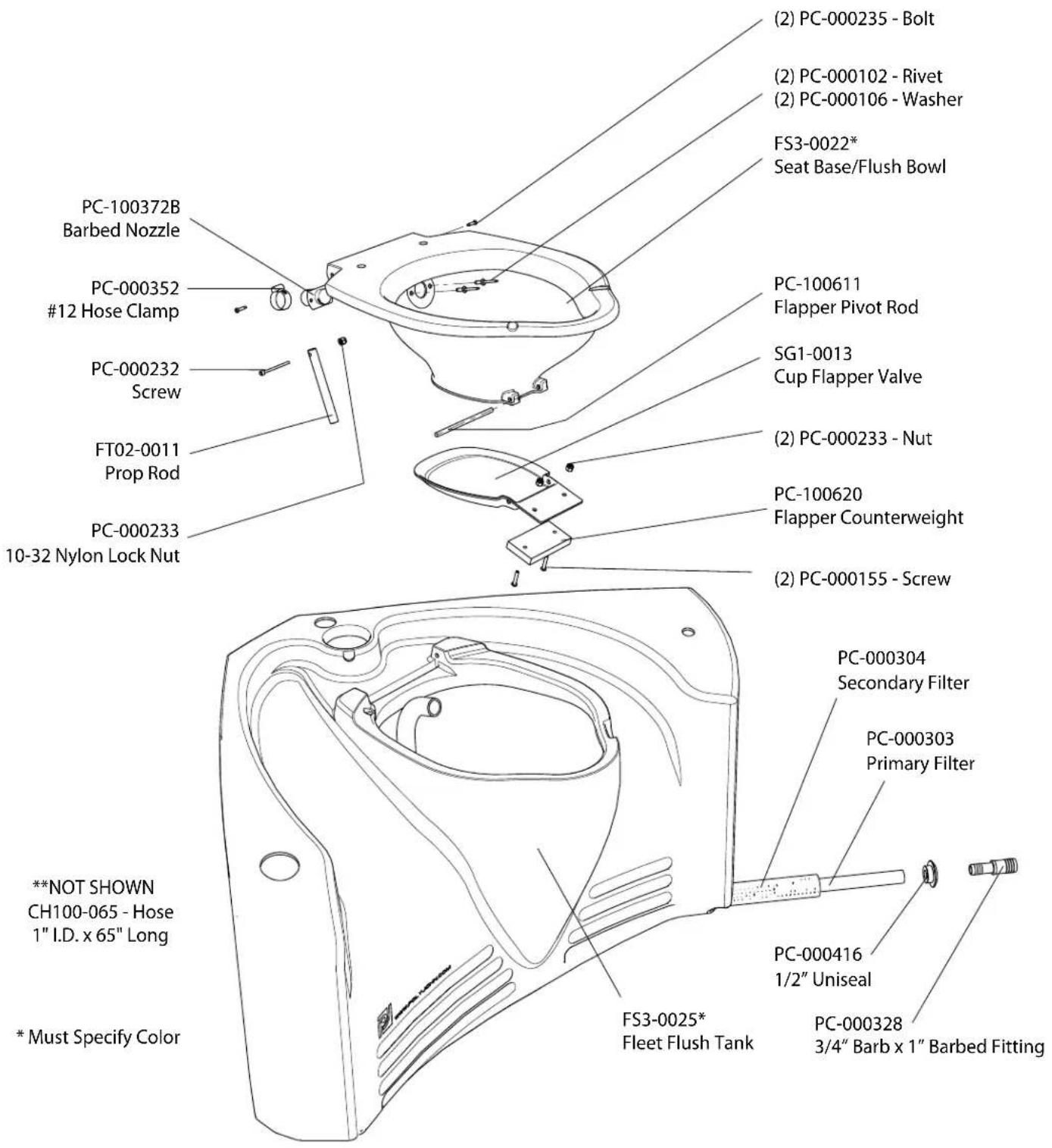
Trouble Shooting
PUMP WILL NOT RETURN UP WHEN PRESSED DOWN WHEN UNIT IS IN FRESH WATER FLUSH MODE: The hoses that go from the sink to the tank and pump are reversed. Carefully lay the unit on it's back. Loosen the clamp holding the hose on the bottom of the sink as well as the clamp holding the hose on the intake port of the pump. Remove these hoses and place the hose that was going to the tank to the intake port of the pump, and place the hose that was going from the intake port of the pump onto the fitting on the bottom of the waste tank. Tighten the clamps, stand the unit back up and retest.
GENERAL STATISTICS AND USEFUL TECHNICAL INFORMATION
| ITEM | STANDARD | METRIC |
| FRESH WATER 1 gal 3.785 ltrOne gal 128 fl . oz 3,780 mlOne qt 32 fl . oz 946.35 mlOne gal 8.33 lb 3.77 kg | ||
| SEWAGEOne gal 10.20 lb 4.62 kgFeces per person per day*.5 lb (26.12 fl . oz) .23 kg Urine per person per day* | 1 qt (32 fl. oz) | .95 ltr |
| Non-Flush Tank Use & Capacity - (120 uses)60 gal < 5 gal charge = 55 gal | 7,040 fl . oz | 208,200 ml |
| Flush Tank Use & Capacity - (75 uses)40 gal < 5 gal charge = 35 gal | 4,480 fl . oz | 132,500 ml |
| Average person urination at special events = 8- 10 fl . oz (237 - 296 ml) | 9 fl. oz / average | 266 ml / average |
| Sink Tank Use & Capacity - (400 uses)20 galSink foot pump dispenses 2 oz per stroke | 2,560 fl . oz6 fl. oz / average | 75.7 ltr177.44 ml / average |
| * per Portable Sanitation Association International (PSAI) | ||
| NOTES:Weather conditions and consumption of foods, liquids and alcoholic beverages can increase usage by 30 to 40%.“Conservative” usage calculations based upon each user producing 59 fl. oz of waste and dispensing 6 fl . oz for hand washing. | ||
CLEANING AND MAINTENANCE
- Use a mild soap to clean all surfaces and component parts.
- The mirror is acrylic, do not use solvent cleaners, use only a mild liquid soap. To maintain a gloss, use a flannel cloth with a good plastic cleaner or polish (such as "Johnson's Pledge").
- Minor scratches and abrasions can be lightly sanded or scrubbed with a mild abrasive cleaner (such as "Soft Scrub") that contains calcium carbonate, hypochlorate bleach and detergents. Be sure to follow the cleaning product directions since these ingredients may cause hazardous gases when mixed with other chemicals. Rinse the cleaned area and buff with a conventional wax.
- Some light scratches may also be hidden by using an industrial hot air gun.
- To keep the interior smelling fresh, spray the interior with a deodorant spray.
For a source of cleaning, deodorizing and paper products contact:
RID IT
2500 GASPAR AVE.
WHITING, IN 46394-2175
800-292-1305 EXTENSION 514
www.rid-it.com
We highly recommend membership in the Portable Sanitation Association International (PSAI); the worldwide authority on portable sanitation services. The PSAI, "Portable Sanitation Industry Certification Program" manual contains a wealth of information on standards and service procedures. For more information contact the PSAI:
PORTABLE SANITATION ASSOCIATION INTERNATIONAL (PSAI)
7800 METRO PARKWAY, SUITE 104
BLOOMINGTON, MINNESOTA 55425 USA
800-822-3020/612-854-8300 FAX 612-854-7560
www.psai.org
OUR MISSION STATEMENT
"PolyJohn is a family owned, state of the art, plastics manufacturing company dedicated to providing its employees with a work environment committed to excellence, and its customers with innovative products, services and technology that meet or exceed their requirements."
THANK YOU FOR PURCHASING POLYJOHN PRODUCTS!
Look for us on the web @PolyJohn.com
- SPECIFICATIONS
- DIMENSION
- IMPERIAL
- METRIC
- POLYJOHN
- USA
- WORLDWIDE
- CANADA
- GENERAL OVERVIEW
- \~\~TOOLS REQUIRED FOR ASSEMBLY!\~\~
- FULL SCALE FASTENER DRAWINGS
- Step 2: Tank-Sink Installation
- Step 4: Sidewall Panels to Door Jamb
- Step 5: Cabana to Base
- Step 6: Hose Connections
- Step 7: Cabana to Base (Continued)
- Step 8: Tank Installation
- Step 9: Sink Installation
- Step 10: Screen Installation
- Step 11: Roof Installation
- Step 12: Vent Stack Installation
- Step 13: Spring Installation
- Step 14: Optional Lock Installation
- Step 15: Door Panel /Slide Latch Installation
- Step 16: Mirror Installation
- Step 17: Toilet Seat Installation
- Step 18: Optional Urinal Installation
- Step 19: Toilet Paper Dispenser
- Step 20: Soap and Paper Towel Dispenser
- GENERAL USE AND MAINTENANCE
- Opening The Sink
- Switching from Fresh Water Flush to Recirculating Flush / Recirculating Flush to Fresh Flush modes
- Locking/Unlocking the Unit (Optional)
- Trouble Shooting
- CLEANING AND MAINTENANCE
- OUR MISSION STATEMENT
- THANK YOU FOR PURCHASING POLYJOHN PRODUCTS!
Brand : PolyJohn
Model : FS3-3013
Category : Toilets