KRA221SXRH - Air conditioner Chief - Free user manual and instructions
Find the device manual for free KRA221SXRH Chief in PDF.

| Product Type | Add-on Arm Accessory for Display Mounting System |
| Brand | Chief (Milestone AV Technologies) |
| Model | KRA221SXRH (Reduced Height) |
| Compatible Mount | K1C Series Column Mount |
| Max Displays Supported | Up to 4 (with KRA226 grommet accessory) |
| Weight Capacity per Display (2-display) | 25 lbs (11.34 kg) |
| Weight Capacity per Display (3-display) | 15 lbs (6.8 kg) |
| Weight Capacity per Display (4-display) | 10 lbs (4.54 kg) |
| Total System Weight Capacity (2-display) | 50 lbs (22.68 kg) |
| Total System Weight Capacity (3-display) | 45 lbs (20.4 kg) |
| Total System Weight Capacity (4-display) | 40 lbs (18.14 kg) |
| Adjustment Range (2-arm) | 90° from pivot, perpendicular to mount centerline |
| Adjustment Range (3-arm) | 60° |
| Adjustment Range (4-arm) | 90° |
| Installation Hardware | Includes #10-24 x 5/8" flat head cap screws and square nuts |
| Tools Required | Not specified, likely screwdriver |
| Material | Steel (assumed) |
| Color | Not specified, likely black or silver |
| Indoor Use Only | Yes |
| Safety Warnings | Exceeding weight capacity may cause collapse; do not use outdoors |
| Compliance | Designed for use with Chief mounting systems |
| Warranty | Not specified, refer to manufacturer |
Frequently Asked Questions - KRA221SXRH Chief
User questions about KRA221SXRH Chief
0 question about this device. Answer the ones you know or ask your own.
Ask a new question about this device
Download the instructions for your Air conditioner in PDF format for free! Find your manual KRA221SXRH - Chief and take your electronic device back in hand. On this page are published all the documents necessary for the use of your device. KRA221SXRH by Chief.
USER MANUAL KRA221SXRH Chief
INSTALLATION INSTRUCTIONS

KRA221 (standard)
KRA221XRH (reduced height)
Kontour™ K1C Add-on Arm Accessory
DISCLAIMER
Milestone AV Technologies and its affiliated corporations and subsidiaries (collectively "Milestone"), intend to make this manual accurate and complete. However, Milestone makes no claim that the information contained herein covers all details, conditions or variations, nor does it provide for every possible contingency in connection with the installation or use of this product. The information contained in this document is subject to change without notice or obligation of any kind. Milestone makes no representation of warranty, expressed or implied, regarding the information contained herein. Milestone assumes no responsibility for accuracy, completeness or sufficiency of the information contained in this document.
Chief® and Kontour™ are registered trademarks of Milestone AV Technologies. All rights reserved.
DEFINITIONS
MOUNTING SYSTEM: A MOUNTING SYSTEM is the primary Chief product to which an accessory and/or component is attached.
ACCESSORY: AN ACCESSORY is the secondary Chief product which is attached to a primary Chief product, and may have a component attached or setting on it.
COMPONENT: A COMPONENT is an audiovisual item designed to be attached or resting on an accessory or mounting system such as a video camera, CPU, screen, display, projector, etc.

WARNING: A WARNING alerts you to the possibility of serious injury or death if you do not follow the instructions.

CAUTION: A CAUTION alerts you to the possibility of damage or destruction of equipment if you do not follow the corresponding instructions.

IMPORTANT SAFETY INSTRUCTIONS!

WARNING: Failure to read, thoroughly understand, and follow all instructions can result in serious personal injury, damage to equipment, or voiding of factory warranty! It is the installer's responsibility to make sure all accessories are properly assembled and installed using the instructions provided.

WARNING: Exceeding the weight capacity can result in serious personal injury or damage to equipment! It is the installer's responsibility to make sure the combined weight of all components between each KRA221 accessory and the desk up to (and including) the display does not exceed the weight limits listed in the table below. Use with products heavier than the maximum weight indicated may result in collapse of the mount and its accessories causing possible injury.
| CONFIGURATION | Max Weight Allowed for EACH Display | Max Weight Capacity of Mounting System |
| 2-DISPLAY CONFIGURATION | 25 lbs(11.34 kg) | 50 lbs(22.68 kg) |
| 3-DISPLAY CONFIGURATION | 15 lbs(6.8 kg) | 45 lbs(20.4 kg) |
| 4-DISPLAY CONFIGURATION | 10 lbs(4.54 kg) | 40 lbs(18.14 kg) |

WARNING: Use this accessory only for its intended use as described in these instructions. Do not use attachments not recommended by the manufacturer.

WARNING: Never operate this accessory if it is damaged. Return the accessory to a service center for examination and repair.

WARNING: Do not use this product outdoors.
--SAVE THESE INSTRUCTIONS--
DIMENSIONS
KRA221 (Standard)
![DYNAMIC LT ARM LENGTH RANGE STRAIGHT - MAX FULL UP/DOWN = MIN 1.88 [47.6] 6.75 [171.5] 10.21 7.12 [359.3] [180.9] 1.97 [50.1]](/content/2026/06/1218885/images/d4a1ffdc0c22031b387e9548db56f2119f926fa25bae64348de795a796625a0b.jpg)

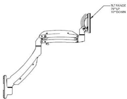

KRA221xRH (reduced height)
![INTERFACE ROTATION RANGE ±90° MOUNTING PATTERN COMPATABILITY 100 X 100 75 X 75 DYNAMIC LIFT ARM LENGTH RANGE STRAIGHT - MAX FULL UP/DOWN=MIN 1.97 [50.1] 10.21 7.21 [259.3] [180.9] 6.75 [171.5] 1.88 [47.6] HEIGHT ADJUST RANGE 17.70 4.29 [451.87] [121.67]](/content/2026/06/1218885/images/ab3130e516b6f32509633a265b4ed4b07e6e4fa2dd3ed2deca3d6d7c8b9dbdc1.jpg)
TOOLS / PARTS FOR INSTALLATION
![3/16" (included) 1/8" (included) A (1) [KRA221 arm] (standard shown) B (1) M4x4mm C (4) M4 x 10mm D (4) M4 x 20mm E (4) M10x5.3x10 F (1) 3/16" G (1) 1/8" H (2) #10-24 x 5/8" J (2) #10-24 K (1) #10-32 x 3/8"](/content/2026/06/1218885/images/2aa2f742bc4cbb73ccb701a4563307dfba807e8ae8a73c60b29bd513c407652a.jpg)
ASSEMBLY AND INSTALLATION
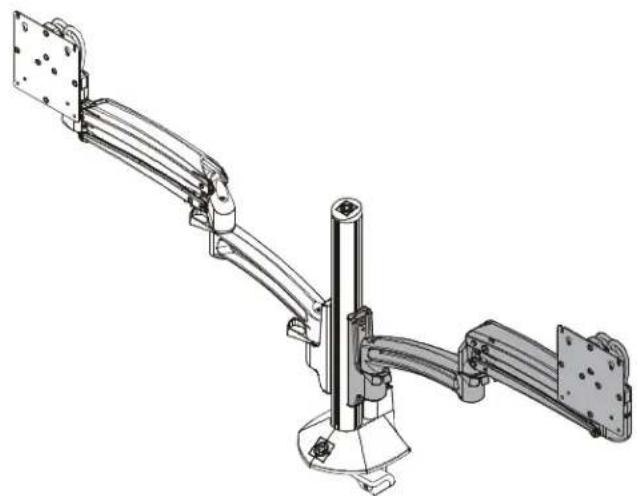
The KRA221 add-on arm can be used to create two-display, three-display or four-display configurations. The installation steps vary slightly for each configuration. In order to create a four-display configuration, the KRA226 grommet accessory must be used as well.
Two Display Configuration
IMPORTANT ! : The only acceptable two display configuration is for the arms to be installed on opposite sides of the column! See Figure 4 for acceptable and non-acceptable configurations.
- Remove cap from K1C column. (See Figure 1)
- Loosen screws holding arm to column and slide arm off of column. (See Figure 1)

Figure 1
- Loosely install two #10-24 x 5/8" flat head cap screws (H) through holes on KRA221 arm (A) and into two #10-24 square nuts (J). (See Figure 2)
- Slide KRA221 arm (A) and removed arm onto K1C column on left and right sides of the column. (See Figure 3)
- Tighten screws to secure each arm to column at desired mounting height. (See Figure 3)
- Replace cap on top of column. (See Figure 3)
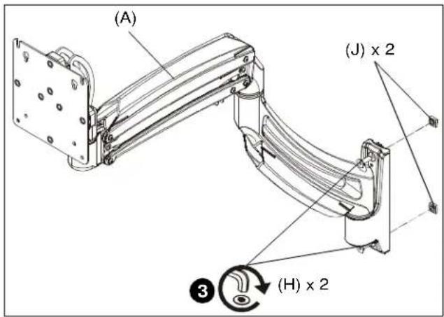
Figure 2
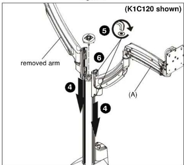
Figure 3
Three Display Configuration
- Remove cap from K1C column. (See Figure 1)
NOTE: If converting a K1C220 mount (dual arm) into a three display configuration, keep existing arms installed and add third column after removing the cap.
- Loosely install two #10-24 x 5/8" flat head cap screws (H) through holes on each KRA221 arm (A) and into two #10-24 square nuts (J). (See Figure 2)
- Slide two KRA221 arms onto K1C column on left and right sides of the column.
- Tighten screws to secure each arm to column at desired mounting height.
- Replace cap on top of column.
Four Display Configuration
- Remove cap from K1C column. (See Figure 1)
- Use KRA226 accessory to install K1C mount to grommet hole. Refer to KRA226 installation instructions for details.
- Loosely install two #10-24 x 5/8" flat head cap screws (H) through holes on each KRA221 arm (A) and into two #10-24 square nuts (J). (See Figure 2)
- Slide three KRA221 arms onto K1C column on left side, right side and back of column.
- Tighten screws to secure each arm to column at desired mounting height.
- Replace cap on top of column.
Display Installation
- Refer to K1C Series installation instructions to install displays to mounting arms.

WARNING: Exceeding the weight capacity can result in serious personal injury or damage to equipment! It is the installer's responsibility to make sure the combined weight of all components between each KRA221 arm and the desk up to (and including) the display does not exceed the weight limits listed in the table. Use with products heavier than the maximum weight indicated may result in collapse of the mount and its accessories causing possible injury.
| CONFIGURATION | Max Weight Allowed for EACH Display | Max Weight Capacity of Mounting System |
| 2-DISPLAY CONFIGURATION | 25lbs(11.34 kg) | 50 lbs(22.68 kg) |
| 3-DISPLAY CONFIGURATION | 15 lbs(6.8 kg) | 45 lbs(20.4 kg) |
| 4-DISPLAY CONFIGURATION | 10 lbs(4.54 kg) | 40 lbs(18.14 kg) |
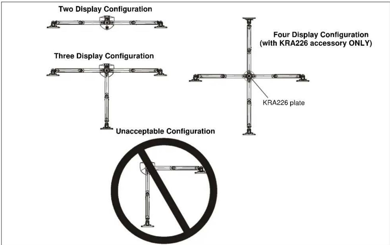
Figure 4
Pivot Adjustment Range
Two-arm Configuration
- Adjust arm angles as desired within a 90 degree range from the pivot point of the arm and a perpendicular centerline of mount. (See Figure 5)

WARNING: Swinging the arm beyond this range may result in the mount slipping of the desk causing serious injury!
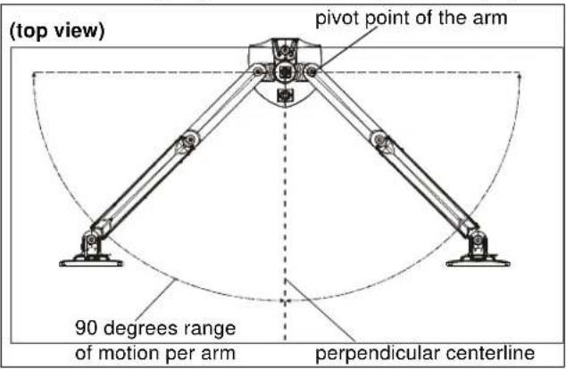
Figure 5
Three-arm Configuration
- Adjust arm angles as desired within a 60 degree range. (See Figure 6)

WARNING: Swinging the arm beyond this range may result in the mount slipping of the desk causing serious injury!

Figure 6
Four-arm Configuration
- Adjust arm angles as desired within a 90 degree range. (See Figure 7)
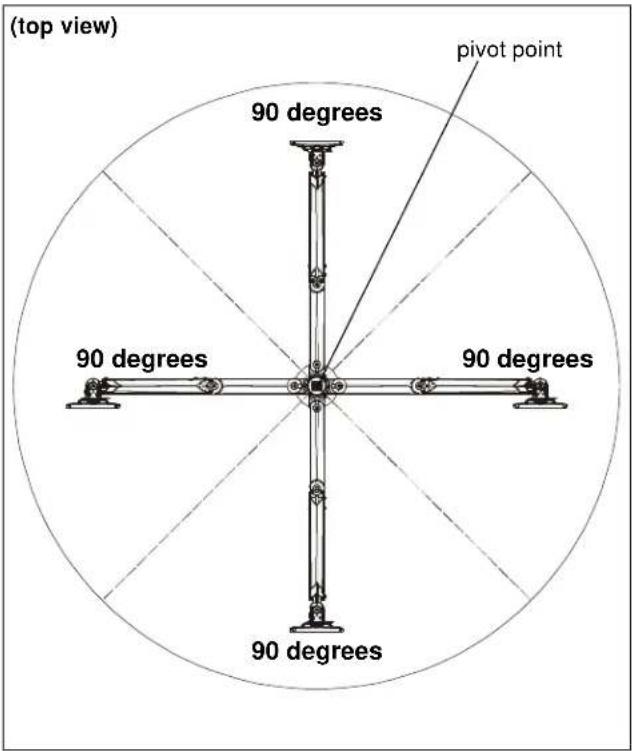
Figure 7
Installation Instructions

- INSTALLATION INSTRUCTIONS
- KONTOUR™ K1C ADD-ON ARM ACCESSORY
- DISCLAIMER
- DEFINITIONS
- IMPORTANT SAFETY INSTRUCTIONS
- SAVE THESE INSTRUCTIONS
- DIMENSIONS
- TOOLS / PARTS FOR INSTALLATION
- ASSEMBLY AND INSTALLATION
- TWO DISPLAY CONFIGURATION
- THREE DISPLAY CONFIGURATION
- FOUR DISPLAY CONFIGURATION
- DISPLAY INSTALLATION
- PIVOT ADJUSTMENT RANGE
- TWO-ARM CONFIGURATION
- THREE-ARM CONFIGURATION
- FOUR-ARM CONFIGURATION
Brand : Chief
Model : KRA221SXRH
Category : Air conditioner