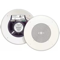
NQ-S181CT-G2 - Loudspeaker Bogen - Free user manual and instructions
Find the device manual for free NQ-S181CT-G2 Bogen in PDF.


| Type | VoIP Ceiling Speaker |
| Brand | Bogen |
| Model | NQ-S181CT-G2 |
| Integrated Amplifier Power | 10 watts |
| Microphone | MEMS digital microphone for talkback |
| Network Interface | RJ-45 Ethernet (Cat5 or higher) |
| Power Source | Power over Ethernet (PoE) IEEE 802.3af |
| CAN Bus Interface | Yes (for digital call switches) |
| Dry Contact Relay | Form C SPDT, 2A rating |
| Ceiling Tile Cutout Size | 8.5 inches square |
| Mounting Method | Ceiling tile with TB8 tile bridge (sold separately) |
| Configuration | Web-based UI or automatic DHCP discovery |
| Firmware Update | Via web UI |
| Reset Button | Reboot or factory reset |
| Optional Accessories | RE84 Recessed Enclosure, TB8 Tile Bridge, MR8 Mounting Ring, NQ-E7020 Digital Call Switch |
| Warranty | 5 years from date of sale |
| Regulatory Compliance | FCC Class A |
Frequently Asked Questions - NQ-S181CT-G2 Bogen
User questions about NQ-S181CT-G2 Bogen
0 question about this device. Answer the ones you know or ask your own.
Ask a new question about this device
Download the instructions for your Loudspeaker in PDF format for free! Find your manual NQ-S181CT-G2 - Bogen and take your electronic device back in hand. On this page are published all the documents necessary for the use of your device. NQ-S181CT-G2 by Bogen.
USER MANUAL NQ-S181CT-G2 Bogen
natural_image
Interior view of a circular speaker grille with an open base showing a NYQUIST NQ-S1810CT-G2 device (no text or symbols on the main subject)NQ-S1810CT-G2
Nyquist Gen-2 VoIP Ceiling Speaker Installation
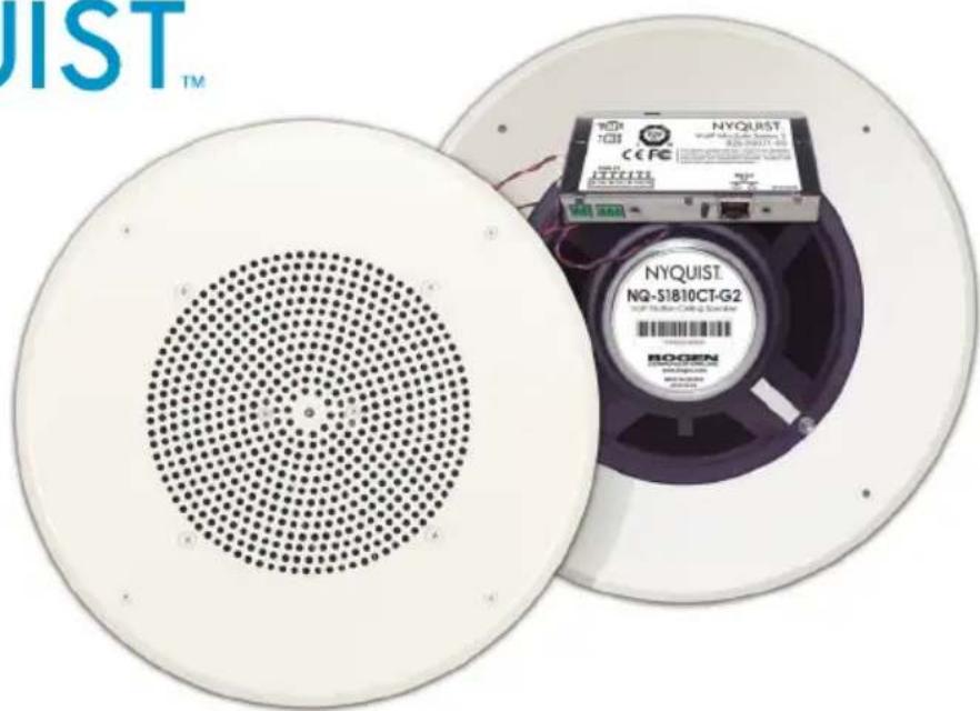
NQ-S1810WT-G2
Nyquist Gen-2 VoIP Ceiling Speaker Installation Manual
With the Nyquist Series Gen-2 VoIP Ceiling Speaker, there is no need for external amplifiers, traditional intercom wiring, or transformer taps to manually set or adjust. Connect the speaker via Cat5 to a Power-Over-Ethernet (PoE) Switch or PoE Injector, and it is ready to use.
The speaker features an integrated 10 watt power amplifier, a CAN Bus interface, a MEMS digital microphone for superior talkback audio, and a Form C SPDT type 2-amp dry contact relay for controlling/overriding third-party devices like AV sources.
The speaker also allows DHCP deployment for easy installation. You can let your Nyquist server automatically discover and configure your speaker, or you can manually configure it through the speaker's web-based user interface (web UI). The web UI also allows easy updating of firmware and setting of parameters for Digital Signal Processing (DSP). For more information about the web UI, refer to the Nyquist Gen-2 VoIP Speakers Configuration Manual.

The layout of the speakers should be planned before installation begins. Layout starts in one corner of the room. The first speaker should be positioned from each wall spaced a distance approximately equal to the ceiling height of the room.
The next speaker in Row 1 should be spaced a distance approximately equal to twice the height of the ceiling. Each additional speaker in the row should use this same spacing.
Row 2 starts at twice the ceiling height distance from row 1 and twice the ceiling height from the wall. The other speakers in this row are also spaced at twice the ceiling height.
Row 3 is again spaced at twice the ceiling height from the previous row. The first speaker starting this row is positioned at one ceiling height distance from the wall (similar to row 1).
Continue this pattern of alternating rows until the room is covered. The spacing of the speakers can be adjusted so that the speakers are evenly spaced in a row and are aesthetically pleasing.
Mounting Equipment/Accessories
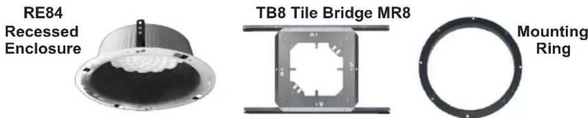
RE84 Recessed Enclosure
The RE84 is an optional back box for ceiling speakers. UL Listed for use where ceiling plenum is part of an air handling system, the RE84 also includes attachment tabs allowing the enclosure to be supported from structures other than the actual ceiling grid.
TB8 Tile Bridge
The TB8 supports the weight of the speaker and recessed enclosure. This is also the item to which the speaker mounting screws attach. The TB8 is required for each speaker assembly installed.
MR8 Mounting Ring
The MR8 Mounting Ring is a cold-rolled steel unit, which will mount any of the Bogen ceiling grilles, for installations where the RE84 is not used.
Speaker Installation
- Remove the tile from ceiling and center the TB8 tile bridge on the back. Use the tile bridge to trace out, and then cut an 8-1/2" square hole. NOTE: It can be more efficient to stack multiple ceiling tiles and then cut the speaker opening in a number of them at one time.
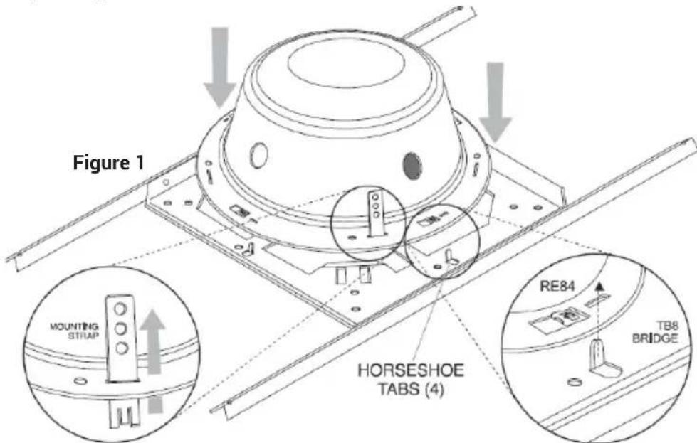
- If using the optional RE84 Recessed Enclosure, bend up the four (4) horseshoe tabs (Figure 1) on the TB8.
Speaker Installation (cont'd)
- Position the TB8 over the hole in the tile and push down the locator tabs (Figure 2).
- Using the 4 supplied screws, attach the speaker to the TB8 Tile Bridge using the 4 clips in the corners of the opening on the TB8 as nuts.
NOTE: Only tighten the screws until the grille is snug against the tile. Over tightening will cause screws to dimple the grille.
- When applicable, use the pluggable CAN bus connector to attach one or more NQ-E7020 Digital Call Switches to the Nyquist VoIP Form C Module 820-00071-00 as shown in Figure 3.

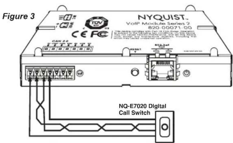
- If the CAN Bus is to be used, ensure CAN_H and CAN_L use (Cat5 10/100) twisted pair cable.
- To connect a third-party device to the dry contact relay output, do one of the following:
a. If the device is looking for a Normally Open contact, connect the device using the NO and COM terminals.
b. If the device is looking for a Normally Closed contact, connect the device using the NC and COM terminals.
Speaker Installation (cont'd)
-
Make the electrical connections using Category 5 or higher Ethernet cable with an RJ-45 connector (Figure 4). The power is supplied by PoE using an 802.3af compliant network switch or PoE injector.
-
Place the entire assembled ceiling tile back into the ceiling grid.

NOTE: Refer to the Nyquist Gen-2 VoIP Speakers Configuration Manual or the System Administrator Manual for detailed instructions on how to configure these speakers.
Using the Reset Button
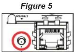
The Reset button (Figure 5) allows you to either reboot the VoIP speaker or to reset the appliance's configuration settings to the factory default settings. For more information about resetting configuration settings, refer to the Nyquist Gen-2 VoIP Speakers Configuration Manual.

Additional Accessories
The Nyquist Gen 2 VoIP Ceiling Speaker can be used with the Nyquist Digital Call Switch NQ-E7020. Refer to the Nyquist Digital Call Switch NQ-E7020 Quick Start Guide.
NOTE: This equipment has been tested and found to comply with the limits for a Class A digital device, pursuant to Part 15 of the FCC rules. These limits are designed to provide reasonable protection against harmful interference when the equipment is operated in a commercial environment. This equipment generates, uses, and can radiate radio frequency energy and, if not installed and used in accordance with the instruction manual, may cause harmful interference to radio communications. Operation of this equipment in a residential area is likely to cause harmful interference; in which case, the user will be required to correct the interference at his own expense.
Limited Warranty, Exclusion of Certain Damages
The NQ-S1810CT-G2 is warranted to be free from defects in materials and workmanship for five (5) years from the date of sale to the original purchaser. Any part of the product covered by this warranty that, with normal installation and use, becomes defective (as confirmed by Bogen upon inspection) during the warranty period will be repaired or replaced by Bogen, at Bogen's option, with new or refurbished product, provided the product is shipped insured and prepaid to: Bogen Factory Service Department: 4570 Shelby Air Drive, Suite 11, Memphis, TN 38118, USA. Repaired or replacement product(s) will be returned to you freight prepaid. This warranty does not extend to any of our products that have been subjected to abuse, misuse, improper storage, neglect, accident, improper installation or have been modified or repaired or altered in any manner whatsoever, or where the serial number or date code has been removed or defaced.
THE FOREGOING LIMITED WARRANTY IS BOGEN'S SOLE AND EXCLUSIVE WARRANTY AND THE PURCHASER'S SOLE AND EXCLUSIVE REMEDY. BOGEN MAKES NO OTHER WARRANTIES OF ANY KIND, EITHER EXPRESS OR IMPLIED, AND ALL IMPLIED WARRANTIES OF MERCHANTABILITY OR FITNESS FOR A PARTICULAR PURPOSE ARE HEREBY DISCLAIMED AND EXCLUDED TO THE MAXIMUM EXTENT ALLOWABLE BY LAW. Bogen's liability arising out of the manufacture, sale or supplying of products or their use or disposition, whether based upon warranty, contract, tort or otherwise, shall be limited to the price of the product. IN NO EVENT SHALL BOGEN BE LIABLE FOR SPECIAL, INCIDENTAL OR CONSEQUENTIAL DAMAGES (INCLUDING, BUT NOT LIMITED TO, LOSS OF PROFITS, LOSS OF DATA OR LOSS OF USE DAMAGES) ARISING OUT OF THE MANUFACTURE, SALE OR SUPPLYING OF PRODUCTS, EVEN IF BOGEN HAS BEEN ADVISED OF THE POSSIBILITY OF SUCH DAMAGES OR LOSSES. Some States do not allow the exclusion or limitation of incidental or consequential damages, so the above limitation or exclusion may not apply to you. This warranty gives you specific legal rights, and you may also have other rights which vary from State to State.
Products that are out of warranty will also be repaired by Bogen Factory Service Department – same address as above or call 201-934-8500, at owner's expense. Returned products which do not qualify for warranty service, may be repaired or replaced at Bogen's option with a previously repaired or refurbished items. The parts and labor involved in these repairs are warranted for 90 days when repaired by the Bogen Factory Service Department. All parts and labor charges as well as shipping charges will be at the owner's expense.
All returns require a Return Authorization number. For most efficient warranty or repair service, please include a description of the failure.
9/2019
- NQ-S1810CT-G2
- Nyquist Gen-2 VoIP Ceiling Speaker Installation
- NQ-S1810WT-G2
- Nyquist Gen-2 VoIP Ceiling Speaker Installation Manual
- Mounting Equipment/Accessories
- RE84 Recessed Enclosure
- TB8 Tile Bridge
- MR8 Mounting Ring
- Speaker Installation
- Speaker Installation (cont'd)
- Using the Reset Button
- Additional Accessories
- Limited Warranty, Exclusion of Certain Damages
Brand : Bogen
Model : NQ-S181CT-G2
Category : Loudspeaker