
SLPPTB22 - Fitness Equipment SereneLife - Free user manual and instructions
Find the device manual for free SLPPTB22 SereneLife in PDF.

| Product Type | Table Tennis Table |
| Brand | SereneLife |
| Model | SLPPTB22 |
| Material | MDF (Medium Density Fiberboard) and Steel |
| Table Top Thickness | 7/10 inch (approx. 18 mm) |
| Wheel Diameter | 3 inches |
| Net Length | 66-1/5 inches (approx. 168 cm) |
| Playing Dimensions (L x W x H) | 107.9 x 60 x 29.9 inches |
| Storage Dimensions (L x W x H) | 63 x 57 x 5.7 inches |
| Playback Dimensions (L x W x H) | 107.9 x 60 x 0.7 inches |
| Color | Matte Grey |
| Assembly Required | Yes, 2-3 adults, approx. 40 minutes |
| Indoor Use Only | Yes |
| Safety Features | Leg levelers, bumper corners, locking casters |
| Included Accessories | Net and clip set, paddle and ball storage |
| Care Instructions | Wipe clean with dry cloth; store in dry indoor area |
| Power Source | None (manual operation) |
| Foldable Design | Yes |
| Playback Mode | Yes, for solo practice |
Frequently Asked Questions - SLPPTB22 SereneLife
User questions about SLPPTB22 SereneLife
0 question about this device. Answer the ones you know or ask your own.
Ask a new question about this device
Download the instructions for your Fitness Equipment in PDF format for free! Find your manual SLPPTB22 - SereneLife and take your electronic device back in hand. On this page are published all the documents necessary for the use of your device. SLPPTB22 by SereneLife.
USER MANUAL SLPPTB22 SereneLife
IMPORTANT SAFETY NOTICE
For your safety and benefit, read this manual carefully before starting assembly and using this product. Failure to follow the instructions and safety precautions in this manual can result in serious injury or damage to equipment.
SAFETY INFORMATION:
- DO NOT allow children to open table. ADULTS ONLY should open, close, adjust, or move table.
- DO NOT leave children unattended with table.
- DO NOT climb, sit, jump, lean, or stand on table. Table is not intended to be weight bearing and serious injury may result.
- Table should only be placed on a flat, level surface to ensure stability.
CARE AND MAINTENACE:
- This table is intended for indoor use only.
- Examine your table regularly for wear and tear. Discontinue use immediately if any defect or damaged parts are found.
- When not in use, store table in a dry, indoor space. Condensation and moisture can cause damage to table top.
- ALWAYS ensure wheel locks are properly engaged when stored to secure table.
GENERAL ASSEMBLY WARNINGS:
- ADULTS ONLY should assemble table. At least two (2) to three (3) adults are required for full assembly. Tables are HEAVY and SHOULD NOT be lifted or assembled alone.
- ALWAYS wear appropriate safety equipment during assembly, especially if operating power tools.
- Assembly area should be clear of children and pets.
- To avoid damage to table top surface, assemble on a dry, flat, and clear area.
- DO NOT tighten hardware until instructed. Only hand tighten at appropriate steps to secure lock nuts.
- Power drills can be useful, but ensure equipment is set to low torque before use. If over-tightened, screws can be stripped.
HARDWARE LIST PAGE
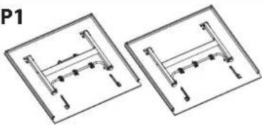 Table Tennis Table Top 2.PCS Table Tennis Table Top 2.PCS | P2 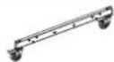 Caster Beams 2.PCS Caster Beams 2.PCS | H4 H5 H6Bolt M8x60MM 4.PCS | Bolt M6x45MM 4.PCS |  M10 Lock nut 12.PCS M10 Lock nut 12.PCS | |||
P3  Middle Plate 1.PCS Middle Plate 1.PCS | H7  M8 Lock nut 8.PCS M6 M8 Lock nut 8.PCS M6 | H8  Lock nut 6.PCS Lock nut 6.PCS | H9   M10 Plastic Spacer 4.PCS M10 Plastic Spacer 4.PCS | ||||
| P4 | P5 | P6Accessory Holder 3.PCSSupport Tube M10 Plastic Washer 8.PCS | H10  M10 Plastic Washer 8.PCS M10 Plastic Washer 8.PCS | H11  4.PCS 4.PCS | H12 [ZZ6K] M6 Plastic Spacer 4.PCSM8 Plastic V M6 Plastic Spacer 4.PCSM8 Plastic V | ||
| P7Net Clipper 2.PCS | P8Net 1.PCS | H13  M10 Washer 24.PCS M10 Washer 24.PCS | H14  M8 Washer 16.PCS M6 M8 Washer 16.PCS M6 | H15  Washer 8.PCS Washer 8.PCS | |||
| TOOLS REQUIRED FOR ASSEMBLY (NOT INCLUDED) | H16  3.0x12MM Screw 4.PCS 3.0x12MM Screw 4.PCS | H17  Stop Spool 8.PCS Stop Spool 8.PCS | H18  Triangle Support Plates 4.PCS Triangle Support Plates 4.PCS | ||||
| Phillips HeadScrewdriver 5/16" Wrench (x2) 1/4" Wrench (x2) | H19M6x15mm Phillips Head Machine Bolt 2.PCS | ||||||
| H1 H2 H3Bolt M10x110MM 4.PCS | Bolt M10x75MM 8.PCS Bolt M8x90MM 4.PCS | ||||||
STEP 1
Hardware Needed:
H2Bolt M10x75MM 8.PCS  |
H13M10 Washer 16.PCS  |
H17Stop Spool 8.PCS  |
H18Triangle Support Plates 4.PCS  |
H6M10 Lock nut 8.PCS  |
P2Caster Beams 2.PCS  |
P2
WARNING:
Clear area of small children and pets

- Before beginning, ensure you have cleared an area large enough for the table to be assembled.
- Align Triangle Support Plate with Caster Beam to line up holes. Thread the bolt in the following order: Bolt (H2) through a Washer (H13), the Caster Beam (P2), a Stop Spool (H17), the Triangle Support Plate (H18), another Washer (H13), and Lock Nut (H6).
- Hand tighten only. DO NOT tighten completely, as nuts/bolts will be adjusted in a later step.
- NOTE: For easiest set up, try to attach both bolts at the same time on each end.
- Repeat steps for all four sections (x4).
STEP 2
Hardware Needed:
| H4Bolt M8x60MM 4.PCS |  |
| H7M8 Lock nut 4.PCS |  |
| H14M8 Washer 8.PCS |  |
| P2Caster Beams 2.PCS |  |
| P3M10 Lock nut 8.PCS |  |

- Attach Middle Plate (P3) to Caster Beams (P2) as shown in the above image.
- Thread the Bolt (H4) through the Washer (H14), both Steel Frames, another Washer (H14) and secure with Lock Nut (H7).
- Repeat for both Caster Beams then tighten completely.
STEP 3
Hardware Needed:
H1Bolt M10x110MM 4.PCS  | |
H6M10 Lock nut 4.PCS  | |
H9M10 Plastic Spacer 4.PCS  | |
H10M10 Plastic Washer 8.PCS  | |
H13M10 Washer 8.PCS  | |
H18Triangle Support Plates 4.PCS  | |
P2Caster Beams 2.PCS  | |
P4Support Tube 4.PCS  | |
P5Strut Tube 4.PCS  |

CAUTION:
DO NOT overtighten the nuts, as this will apply too much pressure to the spacers and may cause them to crack.
IMPORTANT NOTE:
- The Gray Support Tube should have the longer end attached to the Caster Beam, bending up and out.
- The Black Strut Tube should have the longer end attached to the Caster Beam, bending up and out.
- If needed, loosen the Lock Nuts assembled in step 1.
- Thread the bolt in the following order: Bolt (H1) through Washer (H13), Gray Support Tube (P4), Plastic Spacer (H9), Caster Beam (P2), Plastic Washer (H10), Black Strut Tube (P5), Plastic Washer (H10), Triangle Support Plate (H18), Washer (H13), securing with Lock Nut (H6).
- Repeat steps for all four sections.
- Ensure all nuts are securely tightened before moving onto the next step.
STEP 4

WARNING:
Gray support tubes will protrude into assembly area, posing a potential tripping hazard. Exercise caution when completing the remaining assembly steps.
- Place the Strut Tubes (P5) in a upward position and lay the Gray Support Tubes (P4) down in front to avoid interference while attaching the Table Top.
STEP 5
Hardware Needed:

natural_image
Two identical mechanical assembly diagrams showing vertical supports and mounting holes, labeled P1 (no text or symbols on diagrams)Table Tennis Table Top 2.PCS
WARNING:
- At least (2) to three (3) adults are required for the following steps.
• DO NOT attempt to assemble alone, as this may lead to serious injury. - DO NOT open the table to playing position until all support beams and hinges are attached to table frame.
• DO NOT leave table unattended in standing position. Table could be knocked over, causing serious injury or property damage.
ASSEMBLY TIP: if there are three (3) assemblers, have two lift the table with one guiding the table onto the tubes.

- With at least one adult on each side of the table, align the table top U-Beam with the Black Strut Tubes on the Table Base. In an even and controlled manner, lower the Table Top to avoid misalignment while attaching to the Table Base.
- Make sure the pre-drilled holes on the U-Beam line up with the pre-drilled holes on the Black Support Beam. This is important for a later step.
- Continue on to next step. Once complete with Step 8, you will repeat steps 5-8 for the other table top
STEP 6
Hardware Needed:
| H3Bolt M8x60MM 4.PCS |  |
| H7M8 Lock nut 4.PCS |  |
| H11M8 Plastic Washer 4.PCS |  |
| H14M8 Washer 8.PCS |  |
| P4Support Tube 4.PCS |
WARNING:
- DO NOT open the table to playing position until all support beams and hinges are attached to table frame.
- DO NOT leave table unattented in the upright position. Table is not secure yet and can be knocked over causing bodily injury or property damage

Support Attachment
- Attach Gray Support Tube (P4) to the outside of the Table Leg. Thread the bolt in the following order: Bolt (H3) through Washer (H14), through Gray Support Tube (P4), through Plastic Spacer (H11), through Table Leg, Washer (H14), securing with Lock Nut (H7).
- Secure tightly and repeat step for other Gray Support Tube.
STEP 7
Hardware Needed:
H16
3.0x12MM Screw 4.PCS

WARNING:
- DO NOT open the table to playing position until all support beams and hinges are attached to table frame.
- DO NOT leave table unattented in the upright position. Table is not secure yet and can be knocked over causing bodily injury or property damage

• Install screws (H16) into the pre-drilled holes on the Black Strut Tubes (P5).
STEP 8
Hardware Needed:
| H5Bolt M6x45MM 4.PCS |  |
| H8M6 Lock nut 4.PCS |  |
| H12M6 Plastic Spacer 4.PCS |  |
| H15M6 Washer 8.PCS |  |
| P5Strut Tube 4.PCS |  |
WARNING:
- DO NOT open the table to playing position until all support beams and hinges are attached to table frame.
- DO NOT leave table unattented in the upright position. Table is not secure yet and can be knocked over causing bodily injury or property damage

Hinge Attachment
- Ensure the hinge is bent with the elbow on the bottom making, a "V" shape. WARNING: It is very important the hinge is assembled correctly or there could be damage to the table.
- Thread the bolt in the following order: Bolt (H5) Washer (H15), Hinge, Spacer (H12), Strut Tube (P5), Washer (H15), then Lock nut (H8).
- Secure tightly and repeat step for each Hinge.
- Once complete, repeat steps 5-8 for the other Table Top (P1).
STEP 9
Hardware Needed:
P6
Accessory Holder 3.PCS

H8
M6 Lock nut 2.PCS

H16
M6x15mm Phillips Head Machine Bolt 2.PCS


Accessory Holder
- Assemble Accessory Holder by positioning one of the plastic pieces over one of the pre-drilled holes on the H frame.
- Screw into the frame with a bolt (H19).
- Secure the middle metal piece by tightly fitting it between the two plastic pieces.
- Finish the assembly by screwing in the other plastic piece with a bolt (H19).
- If assembled correctly, the metal holder should fit snug between the two plastic holders.
STEP 10
WARNING:
- Area should be clear of children, pets, and any other obstacles when moving the table in different position.
- DO NOT allow children to climb between, under or over any part of the table.
• Adults only should move or open/close the table. - NEVER leave table unattended in standing position without properly stored. Table could be knocked over, causing serious injury or property damage.
- NEVER leave table partially opened or not fully secure.
- Before moving on to the next steps, ensure all support tubes and hinges are assembled correctly and appropriately.
- DO NOT grasp metal legs, support pieces, linkage, or hinges. These parts can move and entrapment and/or pinching of fingers or hands can occur.

natural_image
Simple line drawing of two vertical poles mounted on a wheeled platform with wheels (no text or symbols)
natural_image
Technical line drawing of a mechanical assembly with a rotating frame and supporting structure (no text or symbols)Figure 2 Figure 1

Figure 3 Figure 4

natural_image
Pure mechanical assembly diagram showing two horizontal supports with vertical supports and alignment arrows (no text or symbols)Putting the Table Play-Back and Play Mode
- After correctly assembling both Table Tops, your table can safely be moved from storage mode (Figure 1) to the play-back (Figure 3) or normal (Figure 4) play position.
- Grab the center of the top edge with both hands. WITH CAUTION, gently pull the table outward until you feel the legs rest on the floor as shown.
- Secure table by locking the hinges on both sides of the tabletop. Hinges will lock by pushing up on the elbow.
- Repeat steps for the other Table Top.
Putting the Table in Storage Mode
- Before moving the table tops, ensure hinges have been unlocked
- Grab from the center of the top edge, pulling up and out, do not let go until the table comfortably sits on its own.
- Repeat for the other side of the table.
- Once table is secure, you can safely unlock the wheels and move it about.
- For your safety, lock wheels once you have reached the desired storage or play area. Keep wheels locked until you move the table again. To properly install net, the table will need to be moved into playing position as shown in Fig. 4.
STEP 11
Hardware Needed:
P7
Net Clipper 2.PCS

P8
Net 1.PCS


- Now that your table is in play position, you are ready to assemble the net.
- Secure the Net Clipper (P7) to your Table Top (P1) by clipping it near the center of the two Table Tops.
NOTE: If you plan on putting the Table in storage mode, you will want to clip it to only one Table Top surface as close to the center as possible. The Net Clipper can be moved back once the table is in play position again.
- With white part facing up, attach the Net (P8) to the Net Clipper (P7) by sliding one Net Sleeve into a Net Clipper, then stretching the Net across the table to slide the sleeve into the other Net Clipper.
- Tighten the Net by pulling the cord down and hooking the chain at the bottom of the Net Clipper.
• To adjust the Net height, crank the wheel underneath the Net Clipper.
Features:
- Box Steel Apron for Durability
- Comes with 50% Pre-assembled
- Easy Set-up by Two People in just 40 minutes
- Includes Net and Clip Set
- For Indoor Use Only
- DSG Exclusive
- Swivel Wheels with Locking Casters for Safe Transport
- Matte Grey Finish
- 4/5"x2" Box Steel Apron
- Foldable Design and Simple & Fast Assembly
- Integrated Paddle and Ball Storage
- Leg Levelers and Bumper Corners for Stability and Protection
What's in the Box:
- Table tennis table
- Net and clip set
- Instruction book
Technical Specs:
- Wheel diameter: 3" -inches
• Construction Material: MDF+STEEL
• Table Top Thickness: 7/10" -inches - Lockable Casters Length: 3" -inches
• Net Length: 66-1/5" -inches - Playback Position Dimensions (L x W x H): 107-9/10" x 60" x 7/10"-inches
- Storage Position Dimensions (L x W x H): 63" x 57" x 5-7/10"-inches
- Table Dimensions (L x W x H): 107-9/10" x 60" x 29-9/10"-inches

natural_image
Modern table tennis setup with orange and gray panels, no visible text or symbols on the table itself.serenelife™
Questions? Issues?
We are here to help!
Phone: (1) 718-535-1800
Email: support@pyleusa.com
- IMPORTANT SAFETY NOTICE
- SAFETY INFORMATION:
- CARE AND MAINTENACE:
- GENERAL ASSEMBLY WARNINGS:
- STEP 1
- Hardware Needed:
- P2
- WARNING:
- STEP 2
- STEP 3
- CAUTION:
- IMPORTANT NOTE:
- STEP 5
- STEP 6
- Support Attachment
- STEP 7
- H16
- STEP 8
- Hinge Attachment
- STEP 9
- P6
- H8
- Accessory Holder
- STEP 10
- Putting the Table Play-Back and Play Mode
- Putting the Table in Storage Mode
- STEP 11
- Features:
- What's in the Box:
- Technical Specs:
- serenelife™
Brand : SereneLife
Model : SLPPTB22
Category : Fitness Equipment