UDD-60-HC-S - Pompe à bière Avantco - Free user manual and instructions
Find the device manual for free UDD-60-HC-S Avantco in PDF.

User questions about UDD-60-HC-S Avantco
0 question about this device. Answer the ones you know or ask your own.
Ask a new question about this device
Download the instructions for your Pompe à bière in PDF format for free! Find your manual UDD-60-HC-S - Avantco and take your electronic device back in hand. On this page are published all the documents necessary for the use of your device. UDD-60-HC-S by Avantco.
USER MANUAL UDD-60-HC-S Avantco
natural_image
Exterior view of a black beverage control cabinet with a vertical drain and front panel (no visible text or symbols)178UDD2HC
Beer Dispensers
Base Models:
| #178UDD1HC | #178UDD3HCS | #178UDD60HC | #178UDD2CTS | #178UDD2CTS |
| #178UDD1HCS | #178UDD4HC | #178UDD60HCS | #178UDD3CT | #178UDD72HC |
| #178UDD2HC | #178UDD4HCS | #178UDD36HC | #178UDD3CTS | #178UDD72HCS |
| #178UDD2HCS | #178UDD48HC | #178UDD36HCS | #178UDD4CT | #178UDD378 |
| #178UDD3HC | #178UDD48HCS | #178UDD2CT | #178UDD4CTS | #178UDD378S |
( Variations listed on page 3 )
Note:
Please read the manual thoroughly prior to equipment set-up, operation, and maintenance.
Table of Contents
Model Variations....3
Safety 4
Installation / Operation 5
Uncrating....5
Cabinet Location Guidelines....6
Shelf Installation 6
Drain Installation....7
Electrical 7
Draft Tower Instructions 7
Drain Instructions....8
Startup....8
Adjusting Temperature 9
Defrost System 9
Temperature, Pressure, and Tapping....10
Storage and Handling....10
Knockout CO₂ Installation....11
Changing CO_2 Cylinder 12
Pressure Adjustment on CO₂ Regulator 13
Safety / Warning 14
Operation / Maintenance 15
Stainless Steel Care & Cleaning....13-14
Condensor Coil Cleaning Instructions....15
Stainless Steel Care 16-17
Troubleshooting 18-21
Please Read Handbook Before using Equipment and Keep for Future use.
NOTICE – USE THIS APPLIANCE FOR ITS INTENDED PURPOSES AS DESCRIBED IN THIS USER MANUAL.
A PROPERLY MAINTAINED UNIT WILL GIVE YOU MANY YEARS OF TROUBLE FREE SERVICE.
Base Model Optional Models
| 178UDD1HC | 178UDD12, 178UDD13, 178UDD14 |
| 178UDD2HC | 178UDD23, 178UDD24 |
| 178UDD3HC | 178UDD36, 178UDD38 |
| 178UDD4HC | 178UDD46, 178UDD48 |
| 178UDD36HC | 178UDD363, 178UDD364 |
| 178UDD48HC | 178UDD483, 178UDD484 |
| 178UDD60HC | 178UDD606, 178UDD608 |
| 178UDD72HC | 178UDD726, 178UDD728 |
| 178UDD378 | 178UDD3786, 178UDD3788 |
| 178UDD2CT | 178UDD2CT3, 178UDD2CT4 |
| 178UDD3CT | 178UDD3CT6, 178UDD3CT8 |
| 178UDD4CT | 178UDD4CT6, 178UDD4CT8 |
Base Model Optional Models
| 178UDD1HCS | 178UDD1S2, 178UDD1S3, 178UDD1S4 |
| 178UDD2HCS | 178UDD2S3, 178UDD2S4 |
| 178UDD3HCS | 178UDD3S6, 178UDD3S8 |
| 178UDD4HCS | 178UDD4S6, 178UDD4S8 |
| 178UDD36HCS | 178UDD36S3, 178UDD36S4 |
| 178UDD48HCS | 178UDD48S3, 178UDD48S4 |
| 178UDD60HCS | 178UDD60S6, 178UDD60S8 |
| 178UDD72HCS | 178UDD72S6, 178UDD72S8 |
| 178UDD378S | 178UDD378S6, 178UDD378S8 |
| 178UDD2CTS | 178UDD2CTS3, 178UDD2CTS4 |
| 178UDD3CTS | 178UDD3CTS6, 178UDD3CTS8 |
| 178UDD4CTS | 178UDD4CTS6, 178UDD4CTS8 |
Safety
Warning
DANGER – RISK OF FIRE OR EXPLOSION. FLAMMABLE REFRIGERANT USED. TO BE REPAIRED ONLY BY TRAINED SERVICE PERSONNEL. DO NOT PUNCTURE REFRIGERANT TUBING.
PELIGRO – RRIESGO DE INCENDIO O EXPLOSION. REFRIGERANTE INFLAMABLE UTILIZADO. PARA SER REPARADO SOLAMENTE POR PERSONAL DE SERVICIO CALIFICADO. NO PINCHAR LA TUBERÍA REFRIGERANTE.
DANGER – RISQUE DE FEU OU D'EXPLOSION. LE FRIGORIGÈNE EST INFLAMMABLE. CONFIER LES RÉPARATIONS À UN TECHNICIEN SPÉCIALISÉ. NE PAS PERFORER LA TUBULURE CONTENANT LE FRIGORIGENE.
CAUTION – RISK OF FIRE OR EXPLOSION. FLAMMABLE REFRIGERANT USED. CONSULT REPAIR MANUAL/OWNER'S GUIDE BEFORE ATTEMPTING TO SERVICE THIS PRODUCT. ALL SAFETY PRECAUTIONS MUST BE FOLLOWED.
Installation and Operation
Please read this manual thoroughly prior to equipment setup, operation, and maintenance.
This unit is intended for use in a temperature-controlled environment less than 75 degrees Fahrenheit and 60% relative humidity. Malfunction due to improper conditions is not covered under warranty.
Uncrating
If the unit has recently been transported on its side, please let the unit stand upright for a minimum of 24 hours before plugging it in.
- Remove the outer packaging. All of the packaging (including cardboard, bubbles and plastic wrap) should be removed from the unit.
- Move the unit as close to the final location as possible before removing the wooden pallet.
- Use a screwdriver to remove the screws from the L-bracket connecting the unit to the wooden pallet.
- Remove pallet by unscrewing all base rail anchor brackets. Place pallet to the side.
- Carefully place the cabinet upright.

natural_image
Close-up of a metallic structural joint with bolts and a tool, mounted on a pink base (no visible text or symbols)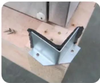
natural_image
Close-up of a metal bracket with black insulation and bolt holes, mounted on a wooden surface (no text or symbols visible)CAUTION – When lifting unit do not use the countertop as a lifting point.
IMPORTANT – Please read below before installation:
- Make sure that the unit has reached the desired temperature before loading the unit with products. This unit is meant for keeping cold products cold, not chilling warm products.
- Make sure that there is proper ventilation around the unit in the area where it will operate.
- Make sure all accessories are installed (i.e., shelves, shelf clips, casters) before plugging the unit in.
- Do not attempt to remove or repair any component of the unit. Consult an authorized service technician for servicing/repair.
- Do not sit/stand inside the unit.
- Please read through the manual in its entirety.
- This unit is designed to perform in a temperature-controlled environment at 60% relative humidity. The unit should be located away from doors, air ducts, and fans that could disrupt airflow and negatively impact performance.
Cabinet Location Guidelines
• Install the unit on strong and leveled surfaces.
- If the surface is uneven, the unit may be noisy.
- The unit may malfunction if the surface is uneven.
- Keep the cooler stable to avoid vibration and noise.
• Install the unit in an indoor, well-ventilated area.
- For best performance, please maintain clearance of 3" on the back of the unit.
- Do not use outdoors. For indoor use only.
- Avoid direct sunlight.
- Unit should be placed far from any heating source to avoid decrease of refrigeration efficiency.
- Avoid installation in a high humidity and/or dusty area.
- Humidity above 60% can cause the unit to rust, to collect condensation, and may decrease efficiency.
-
Dust collected on condenser coil will cause unit to malfunction.
-
Malfunction due to temperatures above 75 degrees Fahrenheit, humidity above 60% , or improperly maintained condenser coil will void the warranty.
-
Select a location away from heat- and moisture-generating equipment.
-
Ambient temperatures above 75 degrees Fahrenheit may cause the compressor to malfunction.
- The unit should not be used in areas over 90 degrees Fahrenheit.
- Malfunction due to ambient temperatures above 75 degrees Fahrenheit will void the warranty.
- Do not install the unit inside a closet or alcove.
- For optimal performance, 3" of clearance is required around all louvered or vented panels, to allow for proper air flow.
- Component failure due to improper installation is not covered under the warranty.
Shelf Installation
Shelves are included with the beer dispensers to provide the option for storage.
- Hook shelf clips onto hanger.
- Place shelves on shelf clips making sure all corners are seated properly.

text_image
Shelf Clip Clip hanger Shelf Clip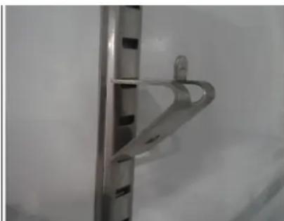
natural_image
Close-up of a metallic bracket with a curved handle, against a plain background (no text or symbols visible)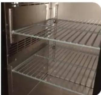
natural_image
Interior view of a stainless steel rack cabinet (no text or symbols visible)Electrical
- Please ensure that the required voltage is being supplied at all times.
- The unit should be plugged into a grounded and properly-sized electrical outlet with appropriate over-current projection. NEVER USE AN ADAPTER PLUG! Please refer to the electrical requirements on the unit's nameplate.
- This unit should have its own dedicated outlet.
- Do not use extension cords.
- Do not unplug your cooler by pulling on the power cord. Grip the plug firmly and pull straight out from the outlet.
- Ensure the unit is not resting on or against the electrical cord.
- If the unit is not in use for a long period of time, please unplug the unit from the outlet.
- To avoid shock and fire hazards, do not plug in or unplug the unit with wet hands.
- After unplugging the unit, wait at least 10 minutes before plugging it back in. Failure to do so could cause damage to the compressor.
Installing Draft Tower

natural_image
Collection of mechanical components including a metallic cylindrical tank, plastic fittings, and bolts (no visible text or symbols)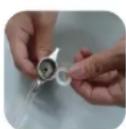


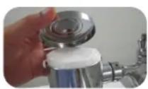

- Connect beer line connector to keg coupler.
- Place rubber washer over draft arm mounting holes in cabinet.
- Put beer line connector down through hole.
- Secure draft arm with four screws.
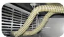
- Insert air hose in draft arm, being careful not to disturb insulation.
- Remove top cover of draft arm and attach air hose clip to the insulating sleeve at the top of the draft arm. This will assure that the hose remains in the proper place at all times, which will keep the beer faucet cold.
- Replace top cover.
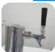
- Screw the handle onto the beer faucet.

natural_image
Close-up of a mechanical component with a central shaft and flange, showing internal structure (no text or symbols visible)
Drain Instructions:
On direct draws, the drain is located at the front of the cabinet. (UDD1 & UDD1S drain into a bottle located inside the unit) To plumb in the drain, connect 12 " PVC pipe to the barbed fitting supplied with the unit. If you would prefer to drain the beer inside the unit (for mobility or where a drain can't be found):
- Use a screwdriver to remove the drain bracket.
- Pull the drain hose so that it is inside the unit.
- Attach a bottle to the drain hose inside the unit.
- Plug the created hole at the bottom of the unit
Startup
- Dial temperature controls set at the no. 4 position gives refrigerators an approximate temperature of 35^ . Digital temperature controls are programmed to operate between 33^ and 40^ with no adjustments. Allow unit to function several hours, completely cooling the cabinet before changing the control settings.
- Excessive tampering with the control could lead to service difficulties. Should it ever become necessary to replace temperature control, be sure it is ordered from your Avantco dealer or recommended service agent.
- Good air flow in your unit is critical. Be careful to load product so that it neither presses against the back wall, nor comes within four inches of the evaporator housing. Refrigerated air off the coil must circulate down the back wall.
RECOMMENDATION:
Before loading product, we recommend you run your Avantco unit empty for 2-3 days. This allows you to be sure the electrical wiring and installation are correct and no shipping damage has occurred. Remember, the Ready Kitchen Warranty does not cover product loss!
Adjusting Temperature
Your new refrigerator is already factory-set to run at optimum temperatures for food safety and should require no adjustments.
Refrigerators are set to cycle between a minimum temperature of 33 degrees Fahrenheit and a maximum temperature of 40 degrees Fahrenheit.
Adjusting the temperature changes the minimum temperature your unit will run at. Your unit will not run constantly at this setting. To change it, follow these instructions:
Temperature Ranges from (7) Coldest to (1) Warmest

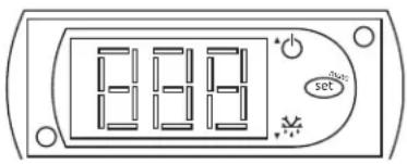
text_image
8:00 setDigital Control Units
- Hold "SET" for 1 sec. The display will flash the current minimum temperature.
- Use the arrow buttons to adjust the minimum temperature you want it to run at.
- Press "SET" again to save your settings.
Always remember to calculate the differential if you change the minimum temperature setting. The cabinet temperature will fluctuate up to +7 degrees over your set minimum temperature as the compressor runs and shuts off. Setting the temperature too high will result in unsafe maximum temperatures and possible health code violations.
Defrost System:
Refrigerator coils are kept below the freezing point (32 degrees Fahrenheit). During compressor downtime, the evaporator fan continues to circulate air through the evaporator coil. This air circulation raises the coil temperature above the freezing point, melting any accumulated frost. Run-off water is drained into the evaporator pan and evaporated. Automatic defrost timers automatically initiate at pre-set intervals and for a pre-determined duration.
Temperature
Correct temperature is a key factor to consider when storing and dispensing draft beer. Too cool or too warm may cause flavor loss and dispensing problems.
Tips on Controlling Temperature
- Keep a thermometer handy.
- Monitor temperature of draft both inside your cooler and at the tap.
- Keep the cooler door(s) closed as much as possible to avoid temperature fluctuation.
- Regular maintenance will help identify potential problems before they become definite problems.
Pressure
Dispensing pressures differ according to:
• The type of draft dispensing system
• The length of draft dispensing line
• The actual draft product
• The temperature of the draft product
- The pressurizing agent: Compressed air, CO2, or specially blended gasses.
Tips on Maintaining Correct Temperature
• Research which pressurizing agent works best with your product and why.
- Monitor your regulators to ensure applied pressure remains constant.
- Keep equipment in good repair.
Tapping
- Do not agitate the kegs unnecessarily.
- If excessive agitation occurs, allow kegs to settle for 1-2 hours before tapping.
- Prior to tapping the keg, ensure that all beer faucets in the serving location are in the off position.
- Completely remove the dust cover (identification cap) from the keg.
Storage & Handling
Draft beer should be treated as a food product. In most instances draft beer is not pasteurized. It is very important that you store and handle it properly. Follow these steps to ensure the highest quality, safety, and consumer satisfaction.
- Draft beer should be immediately stored in a refrigerated cabinet.
- Draft beer products have a recommended shelf life. If you have questions regarding the shelf life of any of your draft products, please consult with your supplying depot or respective brewery representative.
- Kegs should be stored separately from food products. If your cooler is used to refrigerate draft and food products, it is very important that the food not be stored near or on the kegs.
- Keg storage and dispensing areas should be kept clean to prevent any possibility of contaminating your products.
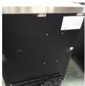
Knockout CO₂ Installation
These are the recommended procedures for installing a remote CO2 container in your Avantco unit.
Tools: Pliers | Power Drill | Silicone Sealer | 1/2" Drillbit
- Remove black knockout plug with pliers. (See images below for plug locations).
- Use drill with 1/2" bit to bore a whole straight back through wall into compressor compartment.
- Snake CO2 line through hole, down and around, exiting behind rear caster underneath grill.
- Seal hole around CO2 line with silicone sealer to prevent cold air leakage. *Depending on setup and amount of kegs, a CO2 manifold may be needed.
natural_image
Close-up of a black stainless steel appliance with visible mounting holes and a small label (no readable text or symbols)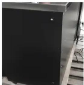
natural_image
Close-up of a black rectangular object with a small white dot, possibly part of a device or component (no visible text or symbols)
natural_image
Close-up of a circular white object on a dark blue surface, possibly a lens or aperture (no text or symbols visible)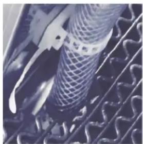
natural_image
Close-up of a mechanical component with mesh texture and curved internal structure (no visible text or symbols)NOTE: In models UDD1 & UDD1S, the CO2 tank (up to 5 lbs. in size) can be placed inside the cooler to maintain complete mobility.
CAUTION: CO2 tanks are potentially dangerous because of the pressure they contain. If you are unfamiliar with their use or the use of a CO2 regulator, seek information from your local distributor, or beverage man before proceeding.
Cleaning Bar System
Draft dispensers, regardless of design, must be cleaned at least every two weeks. Flushing the lines with water only is not enough.
Tools: Pliers | Power Drill | Silicone Sealer | 1/2" Drillbit
Cleaning:
- Prepare cleaning solution as stated on container.
- Disconnect tap from keg.
- Remove beer faucet, unscrew handle and remove valve assembly.
- Put tap and faucet parts in bucket with cleaning solution to soak.
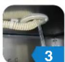
- Use brush to clean faucet parts.
- Rinse all parts thoroughly.
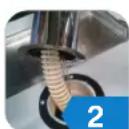
- Fill pump bottle with line cleaning solution.
- Attach hose from pump bottle to beer column tap outlet (be sure rubber gasket is in place to prevent leakage). Allow tap to drain into bucket.
- Pump solution (2-3 times) from bottle through the line until it starts to flow out of the other end. Wait 10 minutes while cleaning solution works on the lines.
- Pump excess solution through lines.
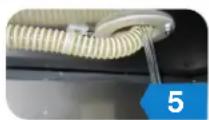
- Rinse bucket, pump bottle and hose thoroughly with clean, cool water.
- Fill pump bottle with clean, cool water and pump through lines until water runs clear.
- When crystal clear water comes through, you're ready to assemble and reattach the faucet and re-tap the keg.
- Draw the water from the beer line.
- Done!
NOTE: Keeping your dispenser and all its parts clean and odor free in conjunction with regular maintenance will get maximum life out of your dispenser.

natural_image
Product photo of a gas washing machine with a cap, tubing, and a vertical tube (no text or symbols visible)
natural_image
Person adjusting a metallic mechanical component with a circular tank and tubing (no visible text or symbols)
natural_image
Close-up of a hand using a mechanical device to measure a black cylindrical component with a bulb, mounted on a metal stand (no visible text or symbols)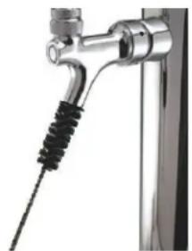
natural_image
Close-up of a metallic faucet with black and white tubing (no text or symbols visible)
text_image
Beer faucet brush Hand pump cleaning bottle Beer line cleanerChanging CO₂ Cylinder
Follow these instructions at ALL times when you replace a CO2 gas cylinder.
- Close cylinder at A.
- Remove tap D from keg. Pull pressure release ring on body of tap to release pressure remaining in line (do not close C).
- Remove or loosen regulator key B by turning counter clockwise.
- Remove regulator from used cilinder at E.
- Remove dust cap from new gas cylinder at E and clear dust from outlet by opening and closing valve A quickly using appropriate wrench.
- Attach regulator to new cylinder at E (use new fiber/plastic washer, if required).
- Open valve A all the way.
- Close valve C.
- Adjust regulator key B by turning clockwise to set pressure (check setting by opening C and pulling and releasing the ring F on the pressure release valve on the body of the tap).
- Tap keg at D with valve C open.
NOTE: DO NOT drop cylinders. DO NOT lay cylinders flat. It requires 1/2 lb. of CO2 to dispense 1/2 barrel of beer at 38°F with 15 lbs. of pressure on barrel.
Pressure Adjustment on CO₂ Regulator
Increasing Pressure:
- Close regulator shut-off C.
- Turn regulator key B clockwise and make setting.
- Tap gauge for accurate reading.
- Open regulator shut-off C and draw beer.
Decreasing Pressure:
- Close regulator shut-off C.
- Untap keg at D and activate tap handle to bleed line. Leave in open position.
- Slowly open regulator shut-off C and simultaneously turn regulator key counter-clockwise to zero reading.
- Close regulator shut-off C and set pressure by turning regulator key clockwise. Check setting by opening and closing valve C.
- Close tap head D (put in OFF position).
- Tap keg at D and open regulator shut-off C.

text_image
Diagram of a gas cylinder with labeled components including a barrel, gas cylinder, and pressure gauges.Safety / Warning
Please pay close attention to the safety notices in this section. Disregarding these notices may lead to serious injury and/or damage to the unit.
ATTENTION
- To minimize shock and fire hazards, be sure not to overload outlet. Please designate one outlet for your unit.
- Do not use extension cords.
- Do not put your hands under the unit while it is being moved.
- When the unit is not in use for a long period of time, please unplug the unit from the outlet.
- After unplugging the unit, wait at least 10 minutes before plugging it back in. Failure to do so could cause damage to the compressor.
UNPLUG CORD
- To minimize shock and fire hazards, please do not plug or unplug the cord with wet hands.
- During maintenance and cleaning, please unplug the unit.
To minimize shock and fire hazards, make sure that the unit is properly grounded.
WARNING
- Do not attempt to remove or repair any component unless instructed by factory.
- Make sure that the unit is not resting on or against the electrical cord and plug.
- To minimize personal injury, do not hang on the doors.
- Do not store any flammable and explosive gas or liquids inside the unit.
- Do not attempt to alter or tamper with the electrical cord.
Operation / Maintenance
WARNING
DISCONNECT THE POWER CORD BEFORE CLEANING ANY PARTS OF THE UNIT.
NOTE: We strongly recommend that any servicing be performed by an authorized service technician.
Loading Product
- Do not block the air duct/fan at the top of the unit. Maintain a minimum of 4" of clearance between products and the fan at all times.
- Ensure all shelves are sitting level and properly secured before loading products.
- Do not store flammable and explosive gas or liquids inside the unit.
Cleaning the Condenser Coil
- For efficient operation, keep the condenser surface free of dust, dirt, and lint.
• We recommend cleaning the condenser coil at least once per month.
Cleaning the Fan Blades and Motor
- If necessary, clean the fan blades and motor with a soft cloth.
- If it is necessary to wash the fan blades, cover the fan motor to prevent moisture damage.
Cleaning the Interior of the Unit
- When cleaning the cabinet interior, use a solvent of warm water and mild soap.
- Do not use steel wool, caustic soap, abrasive cleaners, or bleach that may damage the interior finish.
- Wash door gaskets on a regular basis, preferably weekly. Simply remove the door gasket from the frame of the door, soak in warm water and soap for thirty (30) minutes, dry it with a soft cloth, and replace it.
- Check door gaskets for proper seal after they are replaced.
- Periodically remove the shelves and pilasters from the unit and clean them with mild soap and warm water. To remove the pilasters, first, remove the shelves and shelf brackets. Then, simply lift the pilaster up and out.
Condenser Coil Cleaning Instructions:
A dusty condenser may lead to high energy consumption, less cooling effectiveness, and compressor damage.
The condenser coil is located at the bottom behind the panel.
- Disconnect the electrical power from the unit.
- Remove the front cover and base cover with a screwdriver.
- Using a soft brush and/or vacuum, remove the dirt, lint, etc. from the finned condenser coil in a vertical direction.
- Clean the condenser with a commercial condenser coil cleaner, available from any kitchen equipment retailer. Ex. Noble Chemical Tech Line
- After cleaning, straighten any bent condenser fins with a fin comb.
- When finished, be sure to reinstall the front cover and base cover.
- Reconnect the electrical power to the unit.
Stainless Steel Equipment Care & Instructions
CAUTION: Do not use any steel wool, abrasive, or chlorine based products to clean stainless steel surfaces.
Stainless Steel Destroyers
There are three basic things which can break down your stainless steel's outer defenses and allow corrosion to develop.
- Scratches - Wire brushes, scrapers, and steel pads are just a few examples of items that can be abrasive to stainless steel's surface.
- Deposits - You may have hard or soft water depending on what part of the country you live in. Hard water can leave spots. Hard water that is heated can leave deposits if left to sit too long. These deposits can cause the outer layer to break down and rust your stainless steel. All deposits left from food prep or service should be removed as soon as possible.
- Chlorides - Present in table salt, food, and water, chlorides eat away at the protective layer surrounding stainless steel. Household and industrial cleaners are the worst types of chlorides.
Preventing Rust on Stainless Steel:
1. Use the Correct Cleaning Tools
Use non-abrasive tools when cleaning. The stainless steel's outer layer will not be harmed by soft cloths and plastic scouring pads.
2. Clean Along the Grain
Polishing lines or grain are visible on some stainless steels. Always scrub parallel to these visible lines on stainless steel using a plastic scouring pad or soft cloth. If no lines are visible, use a soft touch with a soft cloth or plastic scouring pad.
3. Use Alkaline, Alkaline Chlorinated, or Non-Chloride Containing Cleaners
While many traditional cleaners are loaded with chlorides, commercial suppliers are providing an ever increasing choice of non-chloride cleaners. One of the best is Noble Chemical Excel Stainless Steel Cleaner. If you are not sure of your cleaner's chloride content, contact your cleaner supplier. If they tell you that your present cleaner contains chlorides, ask if they have an alternative. Avoid cleaners containing quaternary salts as they can attack stainless steel, causing pitting and rusting.
4. Water Treatment
To reduce deposits, soften the hard water when possible. Installation of certain filters can remove corrosive and distasteful elements. Salts in a properly maintained water softener can be to your advantage. Contact a treatment specialist if you are not sure of the proper water treatment.
5. Maintaining the Cleanliness of Your Food Equipment
Use cleaners at recommended strength (alkaline, alkaline chlorinated or non-chloride). Avoid build-up of hard stains by cleaning frequently. When boiling water with your stainless steel equipment, the single most likely cause of damage is chlorides in the water. Heating any cleaners containing chlorides will have the same damaging effects.
6. Rinse & Dry
When using chlorinated cleaners, you must rinse and wipe dry immediately. It is better to wipe standing cleaning agents and water as soon as possible. Allow the stainless steel equipment to air dry. Oxygen helps maintain the passivity film on the stainless steel.
7. NEVER USE HYDROCHLORIC ACID ON STAINLESS STEEL
8. Regularly Restore/Passivate Stainless Steel
Troubleshooting
| Problem Possible Solution | |
| Compressor is Not Running | Fuse blown or circuit breaker trippedReplace fuse or reset circuit breakerPower cord unpluggedPlug in power cordThermostat set too highSet thermostat to lower temperatureCabinet in defrost cycleWait for defrost cycle to finish |
| Cabinet Temperature is too Warm | Thermostat is set too highSet thermostat to lower temperatureAirflow is blockedRe-arrange products to allow for proper airflowMake sure there is at least four inches of clearance from the evaporatorExcessive amount of warm product placed in cabinetAllow adequate time for product to cool downFuse blown or circuit breaker trippedReplace fuse or reset circuit breakerLow refrigerant levelsContact a service technician to check refrigerant levelsProlonged door opening or door ajarEnsure doors are closed when not in useAvoid opening doors for long periods of time |
| Condensing Units Run for Long Periods of Time | Excessive amount of warm product placed in cabinetAllow adequate time for product to cool downProlonged door opening or door ajarEnsure doors are closed when not in useAvoid opening doors for long periods of timeDoor gasket(s) not sealing properlyEnsure gaskets are snapped in completelyRemove gasket and replace if necessaryDirty condenser coilClean the condenser coilEvaporator coil iced overUnplug unit and allow coil to defrostMake sure thermostat is not set too coldEnsure that door gasket(s) are sealing properly |
Troubleshooting
| Problem Possible Solution | |
| Interior Light is Not Working | Poor switch connectionTurn off light switch and turn it back onBulb Is not connectedMake sure the bulb is correctly inserted in the socketBulb has burned outReplace the bulb |
| Condensation is Collecting on the Cabinet and/or Floor | Gasket Is not sealing properlyClean, repair, or replace the gasket as necessaryRelative humidity is above 60%Move unit to area below relative humidity or lower humidity level |
| Other Common Problems | Low refrigerant levelsContact a service technician to check refrigerant levelsDoor Is slightly ajarMake sure door is completely closed |
| Cabinet is Noisy | Loose partsLocate and tighten loose part(s)TubIng VibrationEnsure tubing is free from contact with other tubing or components |
Draft Beer Troubleshooting
| Problem Possible Solution | |
| Flat BeerFoamy head disappears quickly. Beer lacks usual zestful, fresh flavor. | CO2 turned off when not in useKeep lines properly changed at all timesContaminated air source (usually compressed air)Drain air source & refill with clean air.Greasy glassesClean with a grease-cutting cleanerNot enough pressureCheck for leaks, replace air source if necessaryPressure shut off during nightKeep lines properly charged at all timesLoose tap or vent connectionCheck lines, do regular maintenance to preventSluggish pressure regulatorCheck connections, replace is necessaryObstruction in linesCheck lines, clean via instructions on page 13 |
| False HeadLarge soap-like bubbles, head dissolves very quickly. | Dry glassesFlush glasses with clean water and drainImproper pourHold clean glass at 45 degreesPour beer at the midpoint slope of the glassOnce glass fills to hald, tilt upright to 90 degreesFill until there is 1" to 11⁄2" headPressure required does not match beer temperatureResearch or consult your supplier for proper temps/pressures for each draft productCoils in beer lines warmer than beer in kegCheck that the air hose clip is still in placeCheck insulation for damage - repair as necessary |
| Wild BeerBeer is all foam and not enough liquid beer when drawn. | Beer tapped improperlyAvoid agitation in keg prior to tappingTap quickly and at correct temperatureFaucet worn downContact a properly trained maintenance worker to repair or replaceKinks, dents, twists, or obstructions in lineCheck that all lines are clear and properly securedClean lines via instructions on page 13Beer too warm in kegs or linesCheck that the unit is set to proper temperatureCheck that the air hose clip is still in placeCheck for damage in insulationCheck that all lines are clear and properly securedToo much pressureMake sure unit is operating at ideal temperature to match your productCheck to see if pressure gauge is malfunctioningCheck air source |
Draft Beer Troubleshooting
| Problem Possible Solution | |
| Cloudy BeerBeer in glass appears hazy, not clear. | Dirty glass or faucetClean glasses and faucet thoroughly before useBeer over chilled or frozenCheck temperature setting in unit and storage areaBeer temperature variance in kegCheck around keg for hot spotsTry to keep unit door closed as much as possibleHot spots in beer linesCheck that all lines are properly secured, clean, and free of debrisBeer lines damaged or dirtyCheck that all lines are properly secured, clean, and free of debrisClean via instructions on page 13 |
| Bad Taste | Dirty Glass or faucetClean glasses and faucet thoroughly before useKeg too warmCheck temperature setting in unit and storage areaBeer lines too warmCheck around keg for hot spotsTry to keep unit door closed as much as possibleBeer lines dirtyCheck that all lines are properly secured, clean, and free of debrisClean via instructions on page 13Dry glassesFlush glasses with clean water and drainLines not being flushed properly between kegsFlush lines thoroughly with clean water between each keg |