
DIRLC25S23W - Computer Case Panduit - Free user manual and instructions
Find the device manual for free DIRLC25S23W Panduit in PDF.

| Product Type | Computer Case / Air Inlet Duct Assembly for Network Cabinets |
| Brand | Panduit |
| Model | DIRLC25S23W |
| Compatible Cabinets | Net-Access Legacy and N-Type (N***) Cabinets |
| Cabinet Rail Position | Front rails fully forward; rear rails 24.25" - 26.12" back |
| RU Space Required Above Switch | 3 RU (for N-Type cabinets) |
| Components Included | Left Hand Bracket (1), Right Hand Bracket (1), Adjustable Brackets (2), Side Duct Mounting Bracket (1), Side Duct (1), Inlet Duct Box (1) |
| Mounting Hardware | #10-32 nuts, #12-24 screws, #12 star washers (quantities as per installation steps) |
| Material | Steel (typical for Panduit rack accessories) |
| Dimensions (Estimated) | Approximately 2U height, 19" width, depth varies with cabinet |
| Weight (Estimated) | Approximately 5-10 lbs (assembly) |
| Power Requirements | Not applicable (passive airflow component) |
| Main Function | Directs cold aisle air into network equipment to improve cooling efficiency |
| Installation Type | Bracket and screw mounting to equipment rails |
| Airflow Direction | Cold aisle (front) to hot aisle (rear) |
| Maintenance | Periodic inspection for dust buildup; clean with dry cloth or compressed air |
| Safety Precautions | Ensure cabinet is stable during installation; use proper lifting techniques |
| Spare Parts Availability | Contact Panduit for replacement brackets, ducts, or hardware |
| Repairability | Modular design; individual components can be replaced |
| Certifications | Compliant with industry standards (refer to Panduit) |
| Warranty | Standard Panduit warranty (check official documentation) |
Frequently Asked Questions - DIRLC25S23W Panduit
User questions about DIRLC25S23W Panduit
0 question about this device. Answer the ones you know or ask your own.
Ask a new question about this device
Download the instructions for your Computer Case in PDF format for free! Find your manual DIRLC25S23W - Panduit and take your electronic device back in hand. On this page are published all the documents necessary for the use of your device. DIRLC25S23W by Panduit.
USER MANUAL DIRLC25S23W Panduit
Front of Cabinet
(Cold Aisle)
Component Guide
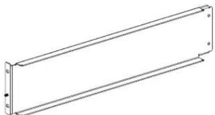
Note: Bracket Has (2) Notches on the Top
natural_image
Pure technical line drawing of a rectangular mechanical component with mounting holes (no text or symbols)(1) Left Hand Bracket

natural_image
Isometric line drawing of a rectangular building with internal door and window (no text or symbols)(1) Inlet Duct Box

natural_image
Technical line drawing of a mechanical component with an inset showing a curved feature (no text or symbols)(1) Right Hand Bracket

(2) Adjustable Brackets
natural_image
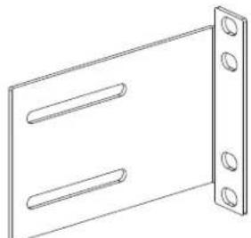
Line drawing of a rectangular panel with two horizontal slots and four corner holes (no text or symbols)(1) Side Duct Mounting Bracket
natural_image
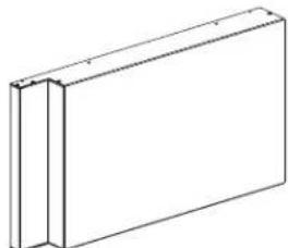
Simple line drawing of a rectangular frame with two vertical panels (no text or symbols)(1) Side Duct
STEP 1
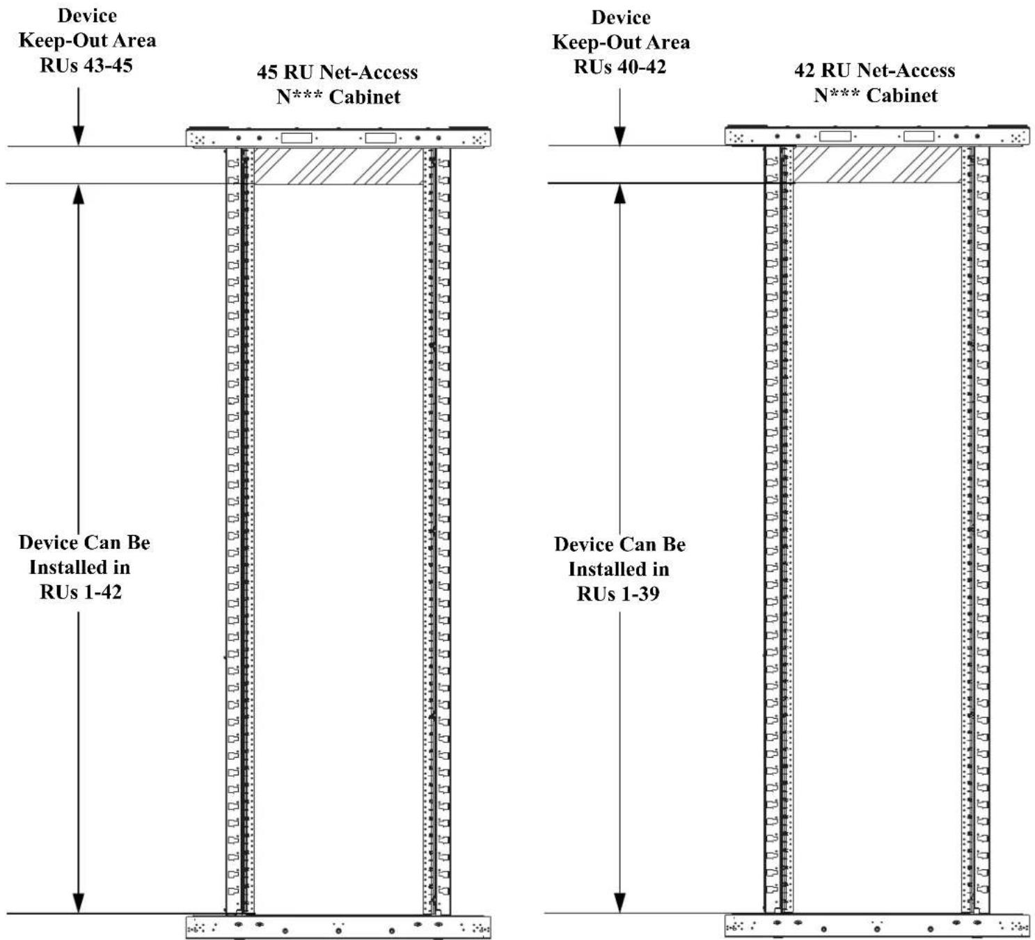
Device Placement (Legacy Cabinets Only)
- Due to physical constraints posed by the front-to-back beams on the Net-Access Legacy cabinet, there are certain areas of the cabinet that the device can not be mounted in when used in conjunction with this inlet duct.
- For Net-Access Legacy cabinets, front equipment rails need to be in full forward position and the rear equipment rails need to be 24.25" - 26.12" back.
NOTES: Numbers-up RU numbering (#1 at bottom) assumed.

For Technical Support: www.panduit.com/resources/install_maintain.asp
STEP 2
Device Placement (N-Type Cabinets Only)
- For Net-Access (N***) Cabinets, there are no device keep out areas. The only restriction on the switch placement is that 3 RU must be left open above the switch.
- For Net-Access (N*** ) cabinets, front equipment rails need to be in full forward position and the rear equipment rails need to be 24.25" - 26.12" back.
NOTES:
Numbers-up RU numbering (#1 at bottom) assumed.
For Technical Support: www.panduit.com/resources/install_maintain.asp
STEP 3
Left / Right Hand Bracket Installation
- Using (2) #10-32 nuts, attach (1) adjustment bracket to the left hand bracket. Set adjustment bracket to fit equipment rail spacing.
- Using (2) #10-32 nuts, attach (1) adjustment bracket to the right hand bracket. Set adjustment bracket to fit equipment rail spacing.
- Attach the left hand and right hand brackets to the cabinet with (8) #12-24 screws and (8) #12 star washers.

For Technical Support: www.panduit.com/resources/install_maintain.asp
STEP 4
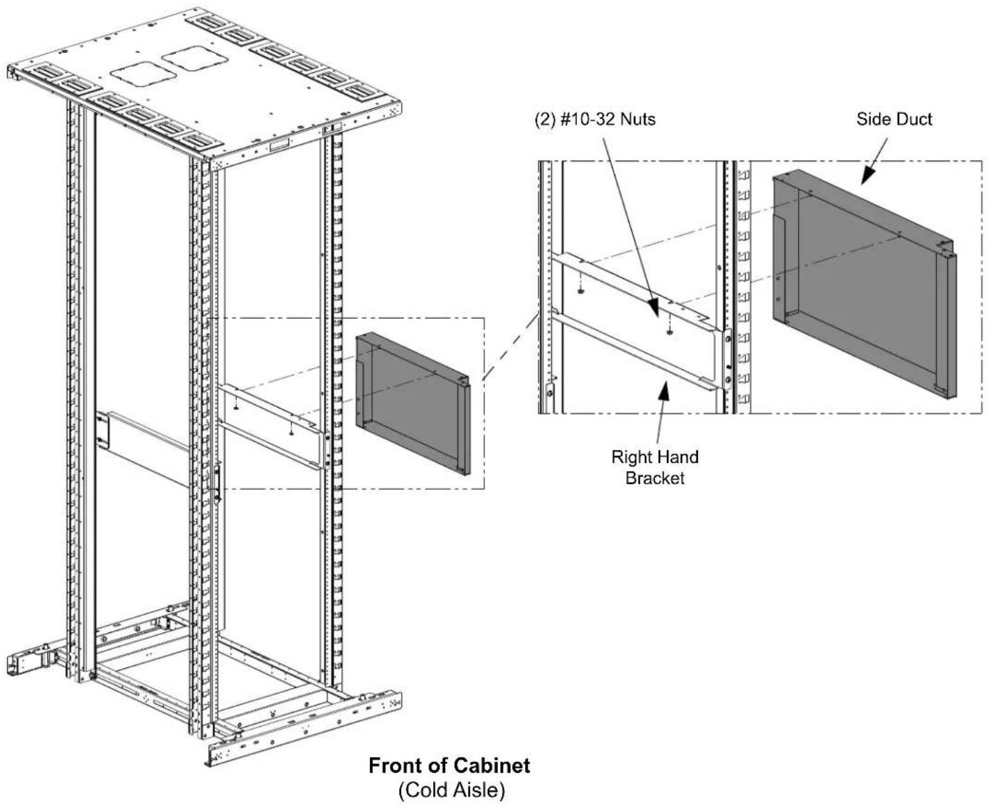
Attaching Side Duct to Right Hand Bracket (Day 1 Installation)
- Slide the (2) threaded studs on the side duct into the (2) slots in the right hand bracket.
- Secure the side duct to the right hand bracket with (2) #10-32 nuts.
Rear of Cabinet
(Hot Aisle)
STEP 5
Attaching Side Duct to Right Hand Bracket (Day 2 Installation)
- From the Rear of the cabinet, slide the side duct into place with the (2) threaded studs on the side duct into the (2) slots in the right hand side bracket.
- Secure side duct to right hand bracket with (2) #10-32 nuts.

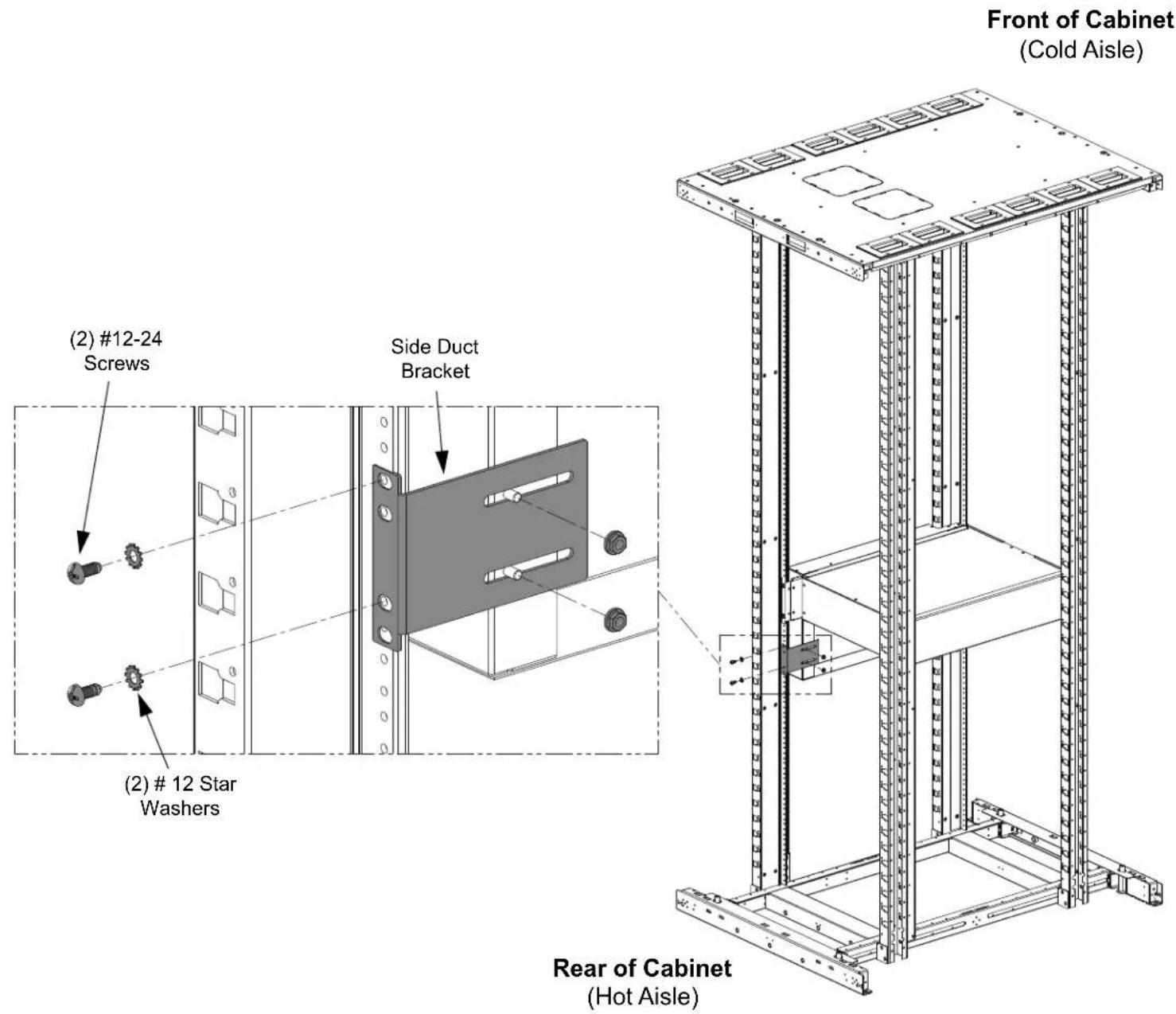
STEP 6
Attaching Side Duct Bracket B
- Secure side duct bracket to the cabinet with (2) #12-24 screws and (2) #12 star washers.
• Using (2) #10-32 nuts, attach side duct bracket to side duct.
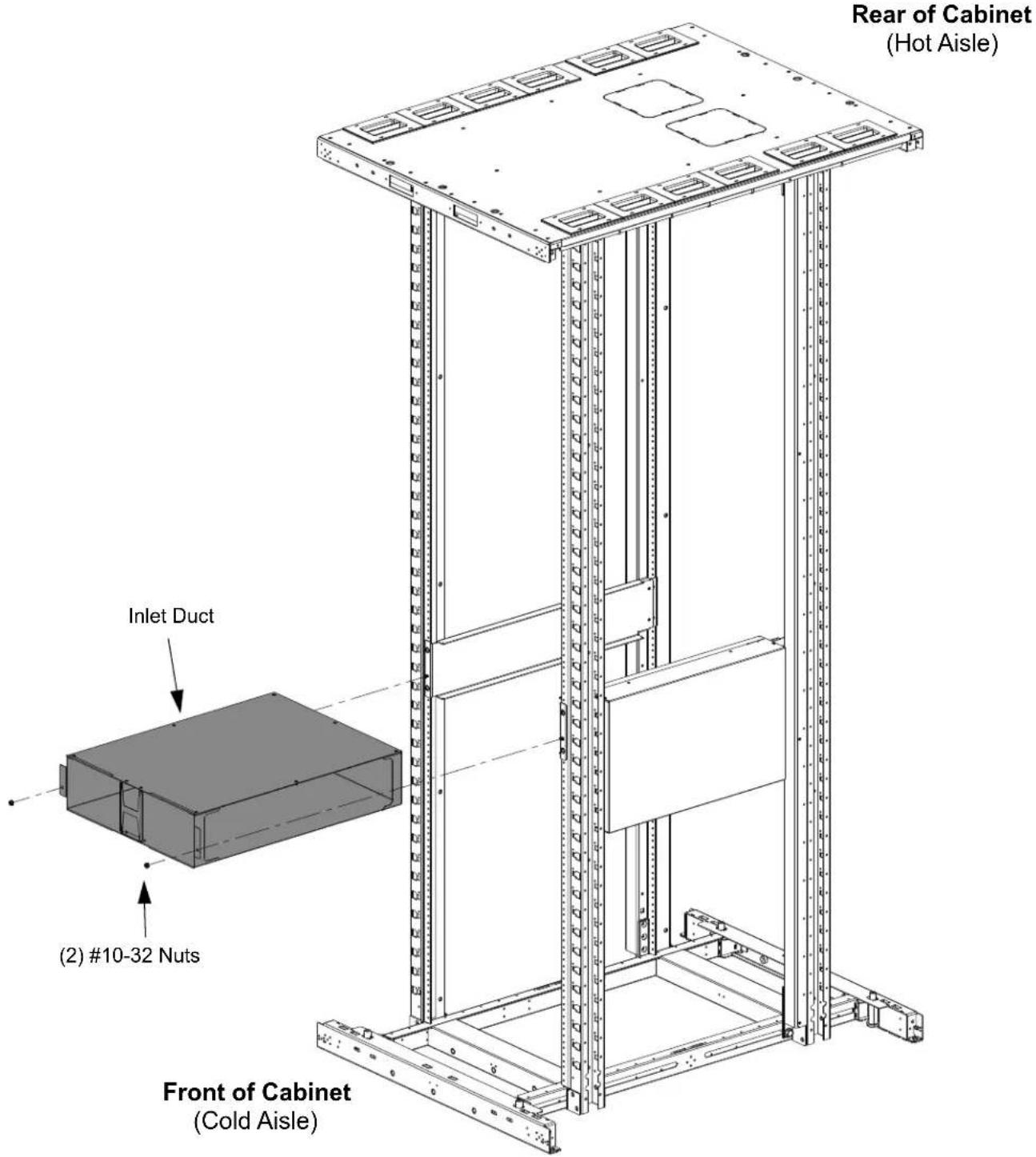
STEP 7
Installing Inlet Duct Box
• Install the inlet duct box by sliding the box into the left hand and right hand brackets, along built in guide flanges and securing with (2) #10-32 nuts.
For Instructions in Local Languages
and Technical Support:
www.panduit.com/resources/install_maintain.asp

www.panduit.com
E-mail:
- STEP 1
- Device Placement (Legacy Cabinets Only)
- STEP 2
- Device Placement (N-Type Cabinets Only)
- STEP 3
- Left / Right Hand Bracket Installation
- STEP 4
- Attaching Side Duct to Right Hand Bracket (Day 1 Installation)
- STEP 5
- Attaching Side Duct to Right Hand Bracket (Day 2 Installation)
- STEP 6
- Attaching Side Duct Bracket B
- STEP 7
- Installing Inlet Duct Box
Brand : Panduit
Model : DIRLC25S23W
Category : Computer Case