
BIFP18L0 - Built-in oven BlueStar - Free user manual and instructions
Find the device manual for free BIFP18L0 BlueStar in PDF.

| Product Type | Built-in Column Freezer |
| Model | BIFP18L0 |
| Brand | BlueStar |
| Cabinet Width | 17-3/4" (451 mm) |
| Cabinet Height | 84" (2134 mm) |
| Cabinet Depth (minimum for flush installation) | 24-1/4" (616 mm) + panel thickness |
| Electrical Requirements | 110-120 V, 60 Hz, 15 A dedicated circuit |
| Water Supply (freezer models) | 1/4" OD copper or PEX tubing, 7.25-72.5 psi |
| Maximum Panel Weight | 75 lb (34 kg) |
| Panel Thickness Range | 3/4" (19 mm) to 1-1/8" (29 mm) |
| Ice Maker | Yes (freezer models) |
| Installation Type | Built-in, panel-ready or stainless door |
| Venting | Front grille, forced air system |
| Leveling | Front leveling feet (11/16" wrench) and rear wheels (1/2" socket) |
| Anti-Tip Safety | Anti-tip brackets or rear wall blocking required |
| Side-by-Side Capability | Yes, with joining kit (heater kit not needed) |
| Door Handle | Included for stainless models; separate for panel-ready |
| Control Display | Touch display with initial test and temperature settings |
| Initial Temperature Stabilization Time | Approximately 6-12 hours |
Frequently Asked Questions - BIFP18L0 BlueStar
User questions about BIFP18L0 BlueStar
0 question about this device. Answer the ones you know or ask your own.
Ask a new question about this device
Download the instructions for your Built-in oven in PDF format for free! Find your manual BIFP18L0 - BlueStar and take your electronic device back in hand. On this page are published all the documents necessary for the use of your device. BIFP18L0 by BlueStar.
USER MANUAL BIFP18L0 BlueStar
natural_image
Symbolic logo featuring a white five-pointed star with a flame-like shape inside, set against a dark blue background (no text or symbols)BLUESTAR®
Column Refrigerator & Freezer
Contents
Safety Information 4
Site Preparation 6
Panel Preparation 8
Installation Instructions 10
Step 1—Uncrate and Inspect Product 10
Step 2—Remove Skid 10
Step 3—Hook up Electrical and Water 11
Step 4—Levelling 11
Step 5—Attach Plastic Connecting Brackets 11
Step 6—Install Two Appliances Side-by-Side 12
Step 7—Attach Wall Blocking 13
Step 8—Install Shoulder Bolts and Set Screws 13
Step 9—Install Panel (Panel-Ready Models) 14
Step 10—Move Appliance into Position 14
Step 11—Install Anti-Tip Brackets 14
Step 12—Adjust Panel (Panel-Ready Models) 16
Step 13—Attach Appliance to Cabinetry 16
Step 14—Attach Door Handle 17
Step 15—Attach Venting Grill 17
Testing and Initial Startup 18
Please read and obey the following types of safety messages to ensure your refrigerator is installed and operated as safely as possible:

DANGER
Will cause serious injury or death if instructions are not followed.

WARNING
Can cause serious injury or death if instructions are not followed.

CAUTION
Can cause minor injury or product damage if instructions are not followed.

WARNING
Electrical Shock Hazard
Follow these basic precautions:
- Plug into a grounded three-prong outlet.
- Do not remove ground prong.
- Do not use an adapter.
- Do not use an extension cord.
- Disconnect power before servicing.
- Replace all parts and panels before operating.
- Use nonflammable cleaner.
- Keep flammable materials and vapors, such as gasoline, away from refrigerator.
- Use two or more people to move and install refrigerator.
Failure to follow these instructions can result in death, electrical shock, or fire.

DANGER
Suffocation Hazard
Remove doors from old refrigerators. Failure to follow these instructions can cause death or brain damage.
Important: Child entrapment and suffocation are not problems of the past. Junked or abandoned refrigerators are still dangerous even if they will sit for a few days. Before you throw away your old refrigerator or freezer, do the following:
- Take off the doors.
- Leave the shelves in place so that children may not easily climb inside.
natural_image
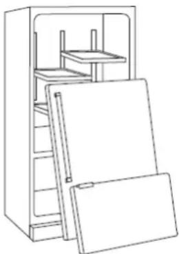
Line drawing of a refrigerator with open doors and shelves (no text or symbols)natural_image
Line drawing of a refrigerator with open doors and shelves (no text or symbols)Cabinet Opening Dimensions
30" Refrigerator or Freezer
Height: 84" (2134 mm)
Width: 29-5/8" (752 mm)
24" Refrigerator or Freezer
Height: 84" (2134 mm)
Width: 23-5/8" (600 mm)
18" Freezer
Height: 84" (2134 mm)
Width: 17-3/4" (451 mm)
30" Refrigerator with 30" Freezer
Height: 84" (2134 mm)
Width: 59-1/8" (1502 mm)
30" Refrigerator with 24" Freezer
Height: 84" (2134 mm)
Width: 53-1/4" (1352 mm)
30" Refrigerator with 18" Freezer
Height: 84" (2134 mm)
Width: 47-1/4" (1200 mm)
24" Refrigerator with 24" Freezer
Height: 84" (2134 mm)
Width: 47-1/4" (1200 mm)
24" Refrigerator with 18" Freezer
Height: 84" (2134 mm)
Width: 41-3/8" (1051 mm)
Cabinet Opening Depth Dimensions
Depth: 24-1/4" (616 mm) minimum plus panel thickness for a panel-ready flush installation. For example, if the panel thickness is 3/4" (19 mm), the minimum depth should be 24-1/4" + 3/4" = 25" (635 mm). Maximum allowed panel thickness is 1-1/8" (29 mm).
Depth: 25-3/8" (645 mm) minimum for a stainless/painted door flush installation.
Depth: 23-1/4" (591 mm) minimum for a stainless/painted door proud installation.
Important: The cabinet enclosure must be securely attached to the kitchen wall to assure the stability of the appliance.


Important: 3-1/2" (89 mm) finished returns will be visible and should be finished to match cabinetry.
Electrical
Location: The electrical outlet should be located in the area marked "Electrical" in Figure 1*.
The electrical outlet may also be located in a cabinet adjacent to the enclosure. However, an access hole would need to be created in the back left corner of the enclosure to route the power cord.
Requirements: The electrical outlet must be on a dedicated non-GFI AC 110-120V, 60Hz, 15 amp circuit for each appliance and accept a three-prong grounding plug. A dedicated 15A circuit breaker should also be installed and should be easily accessible so that it can be easily switched off before performing any installation or maintenance.
Plumbing
(For Freezer Models Only)
Location: The water line should be located in the area marked "Water" in Figure 1*.
Requirements: The water line must use 1/4" OD copper or PEX tubing and have 36" of excess line. The appliance is provided with a water adapter elbow which is suitable for the recommended water pressure and complies with applicable food and water regulations.
Water Pressure: The water pressure must be between 7.25-72.5 psi.
Important: The water line cannot be exposed to temperatures below freezing.
Connect the water line to the household water supply with an easily accessible shut-off valve, not a self-piercing valve. Purge the water line before connecting it to the refrigerator. This will remove any debris that may be present.

CAUTION
Electrical Shock Hazard
Electrical outlet must be checked by a qualified electrician to confirm it meets all applicable electrical codes. Failure to follow these instructions can result in death, electrical shock, or fire.

MISE EN GARDE
* Reference the Site Prep Guides for detailed information regarding your specific installation.
Panel Dimensions
| Description Width (1) | Width (2) | |
| 18" single Column | 17-1/2"(445 mm) | |
| 24" single Column | 23-3/8"(594 mm) | |
| 30" single Column | 29-3/8"(746 mm) | |
| 18" + 24" joined Columns | 17-1/2"(445 mm) | 23-1/2"(597 mm) |
| 18" + 30" joined Columns | 17-1/2"(445 mm) | 29-3/8"(746 mm) |
| 24" + 24" joined Columns | 23-7/16"(595 mm) | 23-7/16"(595 mm) |
| 24" + 30" joined Columns | 23-1/2"(597 mm) | 29-3/8"(746 mm) |
| 30" + 30" joined Columns | 29-3/8"(746 mm) | 29-3/8"(746 mm) |
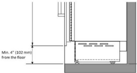
Panel height: 79-7/8" (2029 mm) to match a 4" cabinet toe kick. This is the minimum height from the floor to allow proper ventilation of the appliance. The panel height can be adjusted to match a cabinet toe kick up to 7-3/4" (197 mm) from the floor.
Panel thickness can range from 3/4" (19 mm) to 1-1/8" (29 mm). In the case of a Shaker-style panel the panel may be thinner than 3/4" (19 mm), however, a minimum thickness of 3/4" (19 mm) is required where brackets are screwed to the back of the panel.
Maximum weight for each panel is 75 lb (34 kg).
The hinging mechanism is considered to be 'Zero-clearance'. The panel widths specified above assume the minimum enclosure width is being used and a 1/8" (3.5mm) reveal is desired around the panels. Adjust your panel dimensions accordingly to your own design criteria considering your enclosure width and your reveal. Minimum reveal/gap should not be less than 1/16" (1.5mm).
Prepare the Door Panel
The dimensions of the panels are indicated in the table to the left. Brackets and associated hardware are provided with the product and must be attached to the panel as indicated.
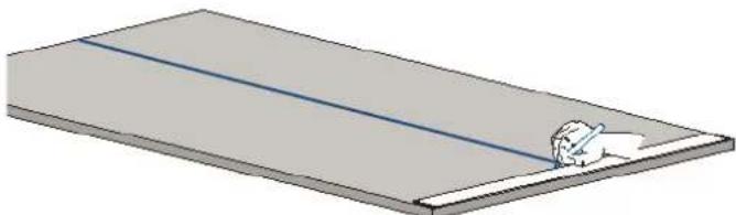
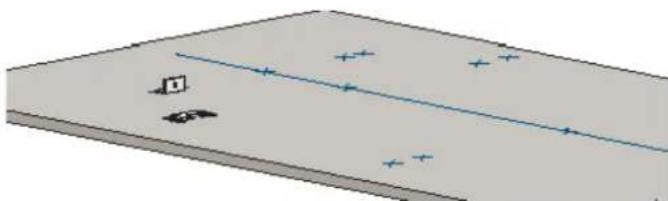
- Draw a vertical center line on the back of the panel from top to bottom.
natural_image
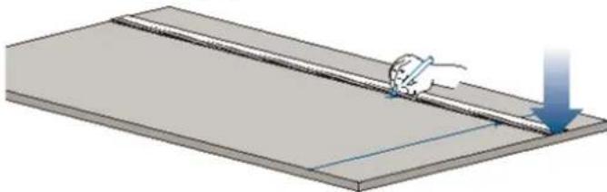
3D diagram of a rectangular plate with a diagonal blue line and a small white object on the side (no text or symbols)- Mark the location of the holes from the top edge of the panel and vertical center line following the values in the table on the next page.
natural_image
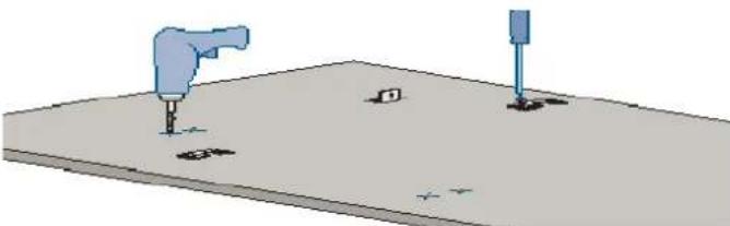
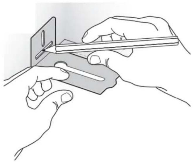
Illustration of a hand using a pen to cut or mark a rectangular object, with a downward arrow indicating motion (no text or symbols present)- Position the brackets on each set of marks and confirm they are aligned. If you choose to drill small pilot holes for the screws, pay special attention to not drill through the thickness of the panel entirely.
natural_image
Simple 3D diagram of a rectangular block with a diagonal line and scattered symbols, no text or labels present.- Screw the brackets in place.
natural_image
3D diagram of a mechanical setup with two tools and mounting holes on a flat surface (no text or symbols)- If using a custom handle, please refer to the mounting instructions for that handle. The handle may need to be installed on the panel prior to installing the panel onto the appliance.
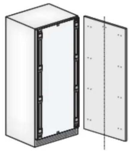
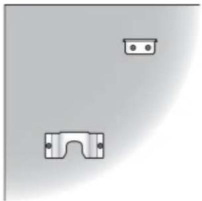
Panel Hole Mounting Positions
natural_image
Diagram of a white electrical cabinet with black frame and side panel, showing internal components and mounting holes (no text or symbols)Top of Panel
natural_image
Simple diagram showing two mechanical components with mounting holes, no text or symbols present| 30" | 24" | 18" | |
| A* | 29-3/8" (747 mm) | 23-3/8" (594 mm) | 17-1/2" (445 mm) |
| B | 13-1/2" (343 mm) | 10-13/16" (275 mm) | 7-7/8" (200 mm) |
* "A" dimensions are for a single appliance installation. See page 8 for panel widths for side-by-side appliance installations.
Hole locations. Dimensions in ( ) are mm.

Tools and Materials
- Mounting kit (included)
• Anti-tipping kit (included)
• Lateral connection kit (included) - 1/8" hex key (included)
- Rivet tool
• Phillips screwdriver - Screws to attach brackets (customer supplied)
- Power drill
• 1/8" drill bit (for wood stud wall) - 5/16" drill bit (for masonry walls)
- Stud finder
- Tubing cutter (for water line)
- 3' of 1/4" OD copper or PEX tubing (for water line)
- Saddle valve (for water line)
• 11/16" (17mm) open end wrench
• 3/4" (19mm) open end wrench - 1/2" (13 mm) socket
- Level
- Gloves
- Safety glasses

WARNING
Tip Over Hazard
Product tips easily when not completely installed. Use two or more people to move and install product. Failure to follow these instructions can result in death or serious injury.

AVERTISSEMENT
The appliance should always be transported in an upright position. Avoid tipping it onto its front side.

MISE EN GARDE
- Before transporting the appliance, check access to the location where it will be installed (door size, maneuvering space in stairwells, etc).
- Use a pallet-jack or appliance cart to move the appliance to the installation site before removing the appliance from the pallet. The appliance should always be transported in an upright position. If this is not possible, transport the appliance on its back.
Step 1 — Uncrate and Inspect Product
- Before starting the installation, uncrate and inspect the product. Remove the packing materials but do not discard the mounting kit, anti-tipping kit, lateral connection kit, joining kit on back of freezer, venting grille, handle pack (if ordered) and associated hardware.
Step 2 — Remove Wood Pallet
Important: Delicate floors should be protected with plywood, hard-board or similar material panels.
- Remove the wood pallet by removing the four shipping bolts (1) with an appropriately-sized wrench or socket. Discard the shipping bolts.
- Remove the front and rear shipping brackets (3, 4). For the front bracket (3), the rear wheel adjusting bolt (2) may need to be loosened with a 1/2" (13 mm) socket or wrench. Avoid over-torqueing this bolt at its stop points so as to not damage the rear leveling system.
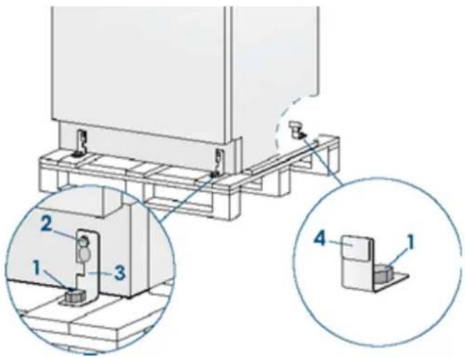
- Retract the front leveling feet with a 11/16" (17 mm) open end wrench.
- From the back of the appliance using a suitable, heavy-duty appliance dolly, take the appliance off the pallet and place it on the floor.
- Roll the appliance(s) into position near the kitchen enclosure, allowing enough space to work behind the appliance(s) for connecting the utilities and in the case of multiple appliances, the joining kit.
Step 3 — Hook Up Electrical and Water
- Unwind the power cord and connect it directly to the wall socket.

natural_image
Diagram of a computer monitor rear panel with a cable and power plug inserted, showing no text or symbols.- Make sure the appliance is in the stand-by condition and that all lights are off; if necessary, press the Power button to switch it off.
- For Freezer Models: Connect the household water line to the 1/4" quick connector elbow adapter supplied with the product.
- Thread the elbow adapter onto the water valve on the back of the appliance. Firmly tighten with fingers. A tool should not be needed to make a proper seal. Turn on the water and ensure all connections are not leaking prior to pushing the appliance into the enclosure.

natural_image
Diagram showing a connector inserted into a housing with a cable, no text or symbols presentStep 4 — Level the Appliance
- Adjust the height of the rear wheels by turning the front adjusting bolts (1) clockwise (raise) or counterclockwise as required.

natural_image
Technical diagram of a structural frame with two labeled components (1), no text or symbols presentImportant: Take care if using a power driver for the rear leveling wheels. Reduce the torque setting to prevent damage to the leveling mechanism.
Important: Do not make large adjustments to just one foot or wheel by itself as the appliance will become unstable. Make small adjustments to each foot and wheel location as you go.
Step 5 — Attach Plastic Connecting Brackets
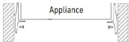
- Using the screws already installed in the sides of the appliance, attach the plastic connecting brackets (A) to the sides of the appliance.
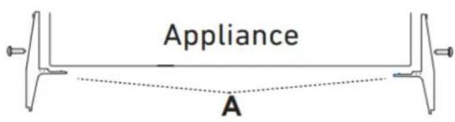
If not installing appliances side-by-side, please skip to Step 7 on page 13.
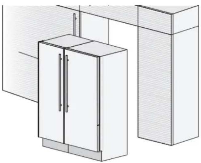
Step 6 — Side-by-side Installation of Two Appliances
Important: There is no need for a heater kit between the appliances.
Important: The appliances must be level with one another to allow the joining brackets to line up.
natural_image
Architectural line drawing of a cabinet with doors and doors, no text or symbols present- Attach the joining brackets to the back of the appliance that are included with the freezer column using the appropriate screws and washers that are also included.
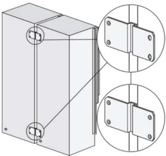
natural_image
Technical illustration of a mechanical assembly with two views of a bracket and mounting holes (no text or symbols)- Next join them at the front connecting each pair of plastic brackets (A) with the supplied rivets using a rivet tool. If a rivet tool is not readily available, an alternate method is to use a #4x.312 long (M3x8mm) bolt and nut to be supplied by the customer. - Complete the installation of the center joining kit by attaching the central profile cover (C) that is included with the freezer column onto the plastic brackets by pushing it until a "click" is heard.


WARNING
Appliances will be front-heavy and may tip before they are secured to the adjacent enclosure wall.

AVERTISSEMENT
Step 7 — Install Anti-Tipping Safety Brackets or Rear Wall Blocking

WARNING
To avoid danger of the appliance tipping over it is mandatory to secure the appliance to the wall by means of the two provided brackets, or if the brackets are not accessible, by means of a wood block at the rear wall of the enclosure.

AVERTISSEMENT
Important: If the top of the appliance is not accessible after it is installed due to the design of the cabinetry/enclosure, install the wood blocking now. If the top of the appliance is accessible, install the anti-tip brackets provided with the appliance as described in Step 11.
Rear Wall Blocking
Place the block about 1/8-1/4" [3-6mm] above the final height of the rear of the appliance. For an 84" installation opening, this would be 81-3/8 to 81-1/2" from the floor. Blocking should be a minimum thickness of 3" (76 mm) from the back wall. Attach with appropriate fasteners into the wall studs. Drywall anchors / toggle bolts are not recommended and can rip out of the wall.

When the appliance is moved into its final position and the legs adjusted, the top of the appliance can make contact with the bottom of the wood block, thus securing the appliance from tipping.
Step 8 — Install Shoulder Bolts and Set Screws (Panel-Ready Models)
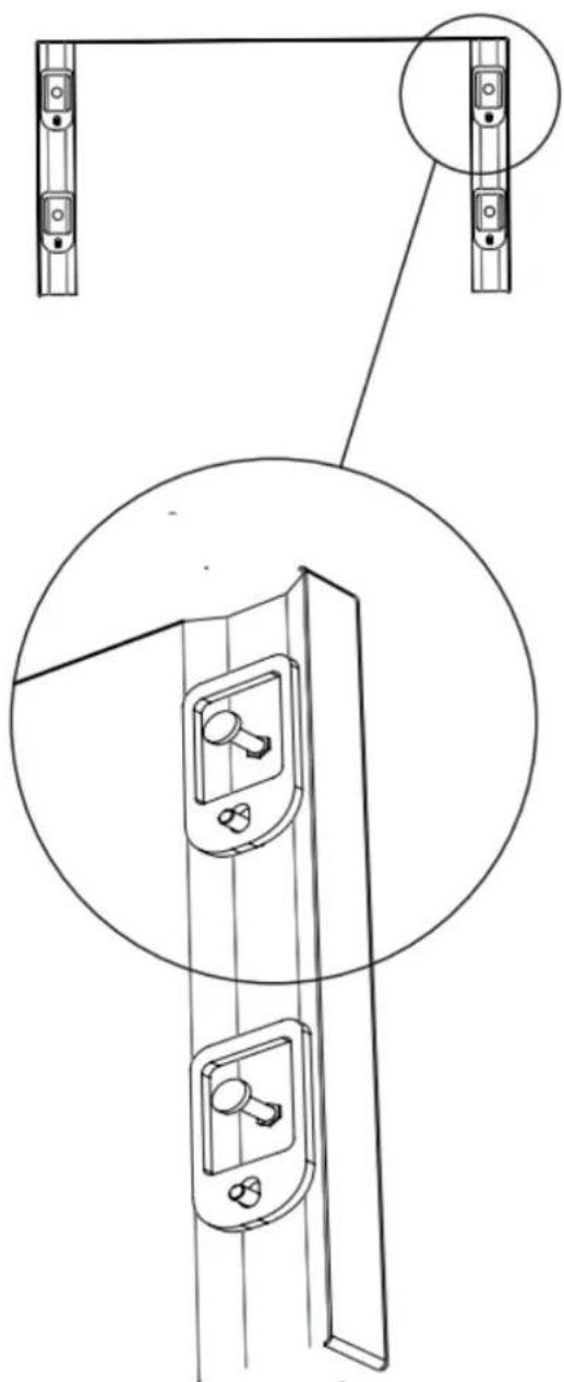
- Prepare the appliance door for panel mounting by threading the shoulder bolts into the recessed threaded hole and the set screws into the other hole as shown below. Ensure the end with the hex key socket is accessible from the inside of the door and not from the outside. Thread the set screws in far enough that they are flush with foam surface on the appliance door exterior face so as not to interfere with hanging the panel. You will adjust these later from the inside of the door.
natural_image
Technical line drawing of a door lock mechanism with mounting brackets and a close-up inset showing internal components (no text or symbols)Step 9 — Install Panel (Panel-Ready Models)
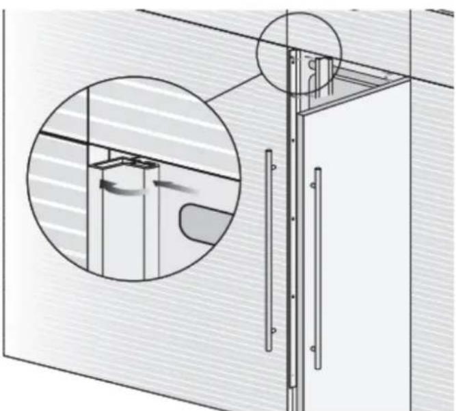
- Align the top center bracket on the panel with the recessed pocket in the door (6). Hook the panel brackets onto the shoulder bolts (7).
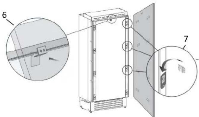
- Install the included screw and washer into the threaded hole on the top center bracket. This screw will be used later to adjust the vertical location of the panel after the appliance is installed into the kitchen opening.
natural_image
3D diagram of a mechanical assembly with arrows indicating force or movement (no text or symbols)Step 10 — Move Appliance(s) Into Position

WARNING
Appliance will be front-heavy and may tip before it is secured to the adjacent enclosure wall.

AVERTISSEMENT
- Roll the product into the cabinet opening, ensuring the water line and the power cord do not interfere.
- Check the level of the appliance(s) and fit to surrounding cabinetry. If the kitchen enclosure is 84" (2134 mm) tall, the appliance(s) will need to be raised significantly. Using a 11/16" (17 mm) wrench for the front leveling feet and a 1/2" (13 mm) socket for the rear leveling wheels, raise the appliance(s) to fit the opening.
Important: Do not make large adjustments to just one foot or wheel by itself as the appliance will become unstable. Make small adjustments to each foot and wheel location as you go. This is especially true on side-by-side installations where the appliances need to stay level to one another.
Step 11 — Install Anti-Tip Brackets
- When using the provided anti-tip brackets, they should be applied as illustrated using the provided screws and wall anchors.
![1-5/8" [45] 2-3/8" [59] 6" [152]](/content/2026/06/1218446/images/f0390dfa384f43959c3ad43d54d7191857021219729409d77dde062b3fe0ab70.jpg)
- Find the mounting holes on top of the appliance, and determine how the bracket must align with the wall.

natural_image
Technical line drawing of a rectangular frame with two vertical supports and a central horizontal beam (no text or symbols)- Mark the wall where the holes are needed.
natural_image
Illustration of two hands using a tool to cut or apply a component, no text or symbols present- For a concrete block wall or 3/4" plywood wall, drill the wall with a 5/16" [8 mm] bit and insert the wall anchor. For a stud wall, drill a 1/8" (3 mm) pilot hole.
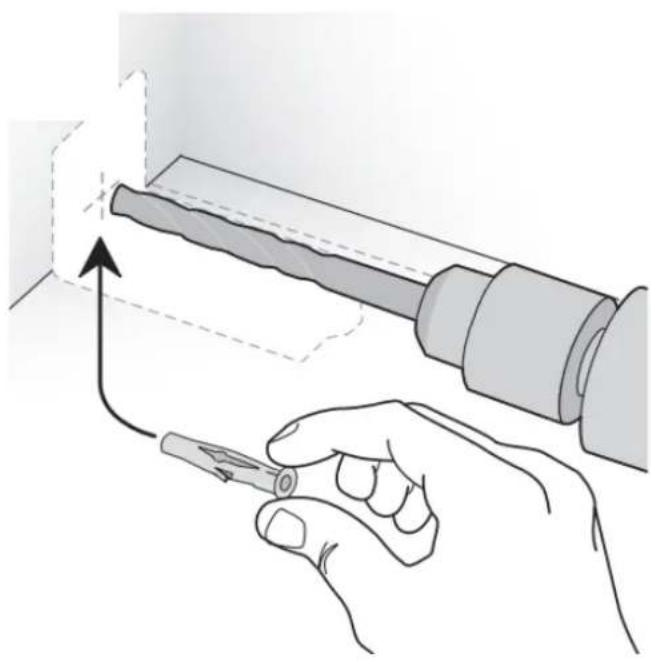
natural_image
Illustration of a hand using a tool to adjust or install a cylindrical component, with no visible text or symbols.- Reposition the bracket and secure it first to the appliance, then to the wall.
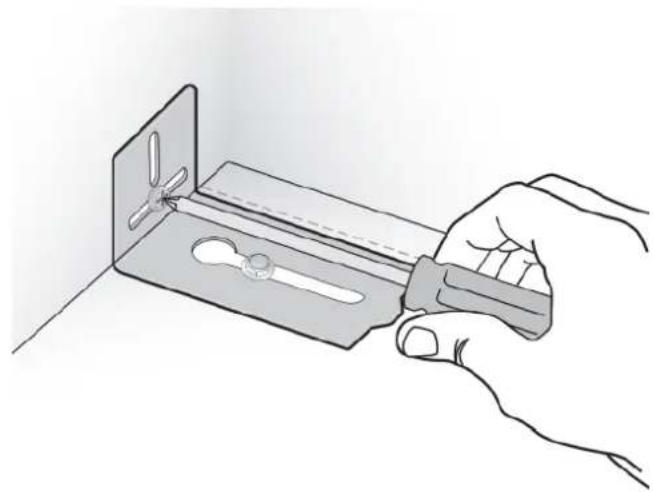
natural_image
Hand holding a tool interacting with a metal bracket containing a saw (no text or symbols visible)In addition, it is required:
- The plastic connecting brackets must be screwed to the cabinets at all provided attachment points as described on page 16, Step 13.
- When two appliances are installed together, the anti-tip brackets are required for each of them.
- The cabinet enclosure must be securely attached to the wall to assure the stability of the appliance.
Step 12 — Adjust Panel (Panel-Ready Models)
- The panel can be adjusted side-to-side at this point to obtain consistent gaps.
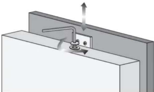
- To adjust the vertical position of the panel after the appliance(s) are installed into the kitchen opening, tighten or loosen the screw in the top center bracket using the supplied hex key to raise or lower the panel (8).
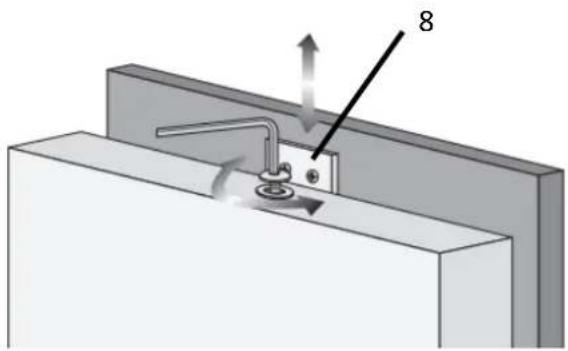
natural_image
3D diagram of a mechanical assembly with labeled component '8' and directional arrows (no text or symbols beyond label)- Adjust the panel depth relative to the face of the cabinetry. Working from inside the door, lift the magnetic seal from the handle side of the door (9) and rotate the plastic covers on the hinge side of the door (10) to expose the holes that contain the shoulder bolts and set screws. Using the included hex key, adjust the panel position in the Z-direction by adjusting the shoulder bolts.
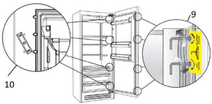
- If the gaps around the panel become inconsistent during the panel depth adjustment, loosen the shoulder bolts and set screws to allow the panel to be adjusted side-to-side.
- Lock the panel location in place by tightening the set screws against the back side of the panel.
- Once the panel is aligned, reinstall the magnetic seal and confirm the door is closing correctly to avoid operational issues.
Step 13 — Attach Appliance(s) to Surrounding Cabinetry
- After leveling the appliance(s) and checking fit of the panel(s) or door(s) to surrounding cabinetry, secure the appliance to the adjacent cabinets by driving screws through the plastic connecting brackets. Screws should be provided by the customer. Keep the door open to ease access to the screws.
- Attach the plastic profiles (B) to the plastic connecting brackets (A). First insert them laterally and then push firmly until a "click" is heard.
Single appliance installation
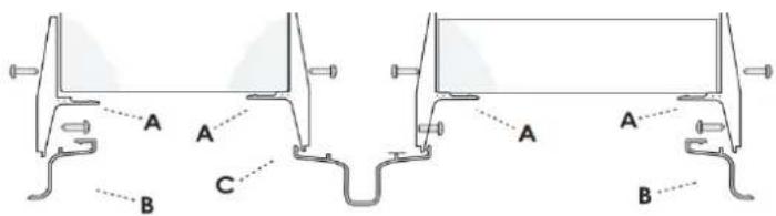
Side-by-side appliance installation
natural_image
Technical diagram of a mechanical assembly with cross-section and detail views (no text or symbols)Step 14 — Attach Door Handle
A BlueStar handle is provided with stainless door models, but must be ordered separately for panel-ready models.
- The handle and nameplate kit is located in protective packaging taped to the back of the appliance.
- It is recommended that two people work together to install the handle.
- Ensure handle mounting studs are threaded finger-tight to the face of the door.

natural_image
Close-up of a hand holding a small black tool near a dark panel, with no visible text or symbols.- Slide handle endcaps onto the handle mounting studs. If the set screw interferes, back out set screw to allow endcaps to slip over handle mounting studs.

natural_image
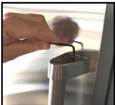
Close-up of a hand adjusting a metal component with a cylindrical object (no visible text or symbols)- Position handle to face of door and with provided hex wrench tighten set screw in top endcap first, then tighten set screw in bottom endcap.
natural_image
Close-up of a hand using a tool to press down a metallic device (no visible text or symbols)Step 15 — Attach Venting Grille
A forced air system assures ventilation through a grille positioned in the lower front part of the appliance. Each BlueStar Column comes with a 8-1/2" (216 mm) tall stainless steel grille.
Important: If using a custom grille, it has to be ventilated with holes. Holes can be in any shape and size, as long as the total area equals 50% of the area defined by dimensions "A" and "B" below.
It is imperative that the grille remain unblocked to ensure proper functionality of the appliance and should be removable to allow for servicing and condenser cleaning.
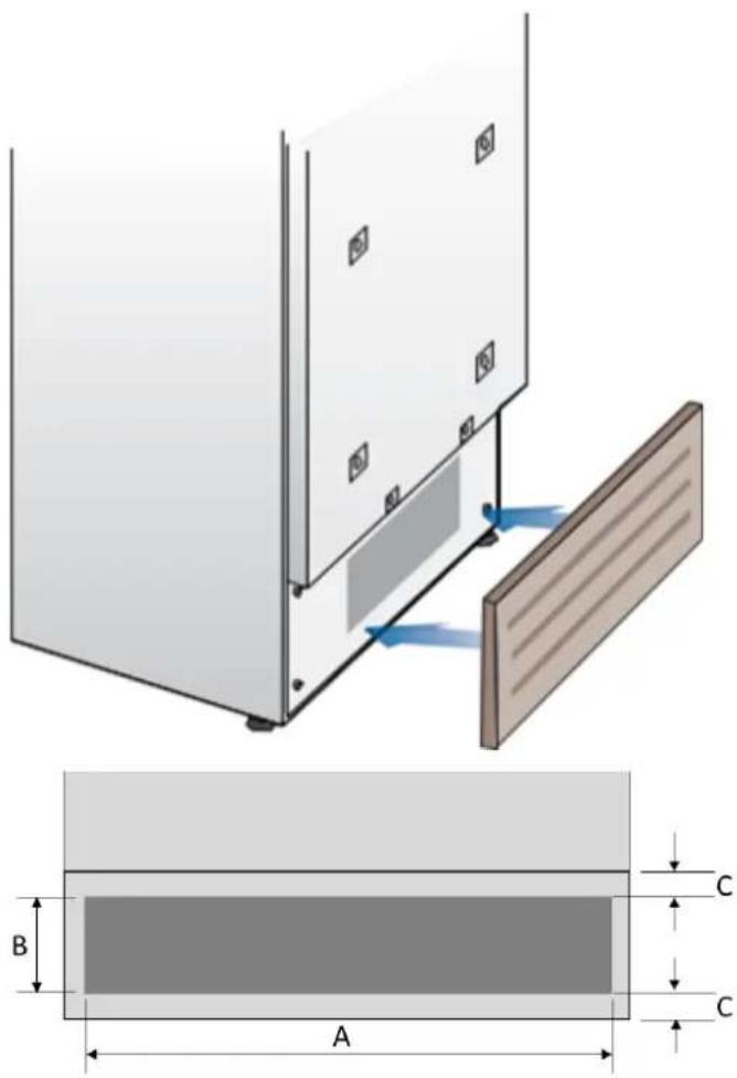
| 18" 24" 30" | |||
| A | 16-1/8" (410 mm) | 22" (559 mm) | 27-15/16" (710 mm) |
| B | >4" (100 mm) | ||
| C | 3/8" (10 mm) | ||
Final Checklist
- Check that the connection to the water system does not have any leaks and that the valve is easily accessible.
- Check that the electrical connection is correctly installed and that the circuit breaker is identified/marked for later use.
- Check that the appliance is level and aligns with adjacent cabinets.
- Check that the anti-tip brackets are secure, and the side connectors are secure with trim in place.
- Check that all adhesive tape and external or internal temporary protective packaging have been removed.
- Check the perfect closing of the doors and the smooth sliding of the drawers and shelves.
- If the appliance has an ice maker, make sure the water filter cartridge is installed. (Unless filtered water is being provided to the appliance.) The water filter is located behind a magnetically attached cover on top of the freezer. Follow instructions provided with the water filter cartridge to install the filter.
Initial Startup
Once the appliance is plugged in, the display will show the BlueStar logo, a brief info screen, then go dark.
Turn the appliance ON by pressing the Power button for three seconds. The display will show a BlueStar logo, then the message "Initial test, please wait..." for 2-3 minutes. After this phase the compressor will start up and remain on until the default temperature (set at the factory) is reached. Allow ample time for the refrigerator to reach this temperature before loading any items (6-12 hrs). During this time, deactivate any error messages by pressing the Alarm button.
Ice Maker (Freezer Models only)
Make sure that the water filter cartridge is properly installed, and the appliance is connected to the water source. Purge air from the water lines by performing the 'Manual Clean' function from the Menu->Functions->Water Filter options. You may need to complete this sequence several times until you stop hearing air sputtering from the ice maker fill tube (Refer to your Use & Care Manual). Place a small tray or bowl inside the ice bin, under the ice maker tray to catch any water during the purge cycle. Once the system is purged of air, switch the ice maker on by touching the ice maker button which will illuminate.
If the appliance has previously started the cooling process prior to the first start-up, it is normal for the Stand-By message to not appear and for other messages to appear, such as Fridge too warm, Freezer too warm, or audible alarm sounds. If this is the case, deactivate acoustic signals by pressing the Alarm button, close the door and wait until the set temperature is reached.
For further information about the appliance operation, refer to the User Manual.
- BLUESTAR®
- Contents
- DANGER
- WARNING
- CAUTION
- Electrical Shock Hazard
- Suffocation Hazard
- Cabinet Opening Dimensions
- Cabinet Opening Depth Dimensions
- Electrical
- Plumbing
- MISE EN GARDE
- Prepare the Door Panel
- Tools and Materials
- Tip Over Hazard
- AVERTISSEMENT
- Step 1 — Uncrate and Inspect Product
- Step 2 — Remove Wood Pallet
- Step 3 — Hook Up Electrical and Water
- Step 4 — Level the Appliance
- Step 5 — Attach Plastic Connecting Brackets
- Step 6 — Side-by-side Installation of Two Appliances
- Step 7 — Install Anti-Tipping Safety Brackets or Rear Wall Blocking
- Rear Wall Blocking
- Step 8 — Install Shoulder Bolts and Set Screws (Panel-Ready Models)
- Step 9 — Install Panel (Panel-Ready Models)
- Step 10 — Move Appliance(s) Into Position
- Step 11 — Install Anti-Tip Brackets
- In addition, it is required:
- Step 12 — Adjust Panel (Panel-Ready Models)
- Step 13 — Attach Appliance(s) to Surrounding Cabinetry
- Step 14 — Attach Door Handle
- Step 15 — Attach Venting Grille
- Final Checklist
- Initial Startup
- Ice Maker (Freezer Models only)
Brand : BlueStar
Model : BIFP18L0
Category : Built-in oven