
KPS-40E - Aaaa Blodgett - Free user manual and instructions
Find the device manual for free KPS-40E Blodgett in PDF.

| Product Type | Self-contained steam jacketed kettle, stationary pedestal model |
| Model | KPS-40E |
| Series | KPS-E Series |
| Capacity | 40 gallons (151 liters) |
| Overall Dimensions (W x D x H) | 26 in x 38 in x 65 in (660 mm x 965 mm x 1651 mm) |
| Minimum Clearance | 3 in (76 mm) on sides and back |
| Power Consumption | 18 kW (standard), 24 kW (optional) |
| Electrical Supply | 3-phase, 208-240V or 480V (see data plate) |
| Heating Method | Electric heating elements, self-generating steam |
| Temperature Range | 140°F to 290°F (60°C to 144°C) jacket temperature |
| Thermostat Control | Adjustable dial from 1 to 10 |
| Construction Material | Stainless steel bowl and exterior |
| Jacket Type | Steam jacket with distilled water, rust inhibitor, and antifreeze |
| Draw-off Valve | 2 in or 3 in vulcanized rubber-coated stem valve |
| Safety Features | Low water cut-off, safety relief valve, tilt interlock (not on KPS), grounding terminal |
| Gauge | Vacuum pressure gauge (reads 22-30 in Hg below 0 PSI when cold) |
| Cover | Stainless steel cover |
| Installation | Bolt down with 5/16 in lag bolts, seal with Silastic |
| Cleaning | Mild detergent and warm water, nylon brush; avoid corrosive agents |
| Maintenance | Check vacuum, bleed air if needed; clean after each use |
Frequently Asked Questions - KPS-40E Blodgett
User questions about KPS-40E Blodgett
0 question about this device. Answer the ones you know or ask your own.
Ask a new question about this device
Download the instructions for your Aaaa in PDF format for free! Find your manual KPS-40E - Blodgett and take your electronic device back in hand. On this page are published all the documents necessary for the use of your device. KPS-40E by Blodgett.
USER MANUAL KPS-40E Blodgett
KPS-E, KLS-E AND KLT-E SERIES
PRODUCT LINE
natural_image
Exterior view of a stainless steel mixing press or mixer vessel (no visible text or symbols)STATIONARY PEDESTAL MODELS
KPS-20E
KPS-25E
KPS-30E
KPS-40E
KPS-60E
KPS-80E
KPS-100E
natural_image
Exterior view of a stainless steel industrial mixing vessel with control panel and pressure gauge (no visible text or symbols)STATIONARY TRI-LEG MODELS
KLS-20E
KLS-30E
KLS-40E
KLS-60E
KLS-80E
KLS-100E
natural_image
Exterior view of a stainless steel mixing vessel with control panel and support legs (no text or symbols visible)TILTING TRI-LEG MODELS
KLT-20E
KLT-30E
KLT-40E
KLT-60E
KLT-80E
KLT-100E
BLODGETT
Your Service Agency's Address:
Model
Serial number
Kettle installed by
Installation checked by
IMPORTANT
WARNING: Improper installation, adjustment, alternation, service or maintenance can cause property damage, injury or death. Read the installation, operation and maintenance instructions thoroughly before installing or servicing this equipment.
FOR YOUR SAFETY
Do not store or use gasoline or other flammable vapors or liquids in the vicinity of this or any other appliance.
The information contained in this manual is important for the proper installation, use, and maintenance of this kettle. Adherence to these procedures and instructions will result in satisfactory baking results and long, trouble free service. Please read this manual carefully and retain it for future reference.
ERRORS: Descriptive, typographic or pictorial errors are subject to correction. Specifications are subject to change without notice.
TABLE OF CONTENTS
INSTALLATION
Introduction....2
Service Connections 3
Installation Instructions 6
Operating & Cleaning Instructions 7
DESCRIPTION
Floor model kettles are self-contained, self-generating steam jacketed vessels for cooking large volumes of liquid and semi-liquid food products. All models include a hemispheric shape based on double-wall construction forming a steam jacket reservoir around the lower two-thirds of the kettle. The reservoir is charged with distilled water, rust inhibitor and antifreeze solution and is vacuum-sealed. Kettles are equipped with electric heating elements and controls including a low water cut-off device for protection of heating elements.
Two model series differ in that KLT-__E units are leg-mounted tilting kettles while KPS-__E units are pedestal mounted stationery kettles. Optional leg mounting of the pedestal models is designated by the model number series KLS-__E. The missing figures of the model numbers are the two digits representing the kettle capacity, ie, KLT-20E for a 20 gallon tilting kettle.
BASIC FUNCTIONING
Self-contained kettles operate by generating steam in the kettle reservoir; the sequence of functioning, which occurs during operation, is as follows:
-
Operator places the power switch in the ON position and sets the thermostat knob at the required setting from "1" to "10" - 140° to 290°F (60° to 144°C) - jacket temperature.
-
Control circuit is normally completed to the thermostat control if two standard conditions exist:
a. Water level in kettle jacket is adequate to prevent circuit interruption by the low water cut-off device. An activated cut-off is evidenced by the Low Water light turning on and heating element cut off.
b. Kettle is in vertical position with circuit completed through the tilt interlock switch (KLT-E series only).
-
Thermostatic control contacts close to energize heater contactor coils and turn temperature Indicator light on.
-
Power is applied to heaters through closed contactor power contacts.
-
As temperature of water rises in kettle reservoir, the steam pressure increase is indicated by the vacuum pressure gauge.
NOTE: Gauge normally reads 22-30 IN. Hg (74-100 k/Pa) (below 0 PSI, prior to heaters turning on. Air is eliminated from the system when jacket is filled (with the kettle reservoir at a pressure above 0 PSI) by opening the bleed vent one full turn for 10 seconds and closing.
- When temperature of steam in the reservoir reaches the temperature coinciding with the thermostat setting, the thermostat switch opens to break the circuit to the contractor coils and shuts off the elements. Any number of on and off cycles of the control thermostat, contactors and elements will occur as required to maintain thermostat setting,
SERVICE
Required service, both preventive and corrective. is explained in the maintenance section. Should repairs be required, a network of authorized agencies is available to assist with prompt service. A current Directory of Authorized Service Agencies may be found by visiting our website, www.blodgett.com.
The model and serial numbers must be referenced when corresponding with Blodgett. The data plate containing the serial number pertaining to the equipment is located on rear of kettle.
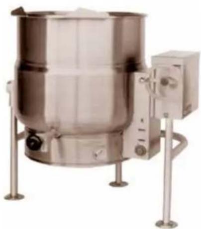
TILTING TRI-LEG KETTLES
DIMENSIONS
| MODEL A B | C D E F | G H J(2") | J(3") | K(2") | K(3") | L M | |||||||||
| KLT-20E 21 | [533] | 18[457] | 38[965] | 36[914] | 15[381] | 18[457] | 14[356] | 19.25[489] | 14.75[375] | 15.5[394] | 18[457] | 17.5[445] | -63.5[1613] | ||
| KLT-30E 24 | [610] | 20[508] | 38[965] | 39[990] | 16.5[419] | 19[483] | 12.38[314] | 19.25[489] | 16.75[425] | 17.25[438] | 16[406] | 15.5[394] | -66.5[1689] | ||
| KLT-40E 26 | [660] | 22.5[572] | 38[965] | 41[1041] | 17.5[445] | 23[584] | 10[254] | 20.25[489] | 17.5[445] | 18.5[470] | 13.5[343] | 13[430] | -68.5[1740] | ||
| KLT-60E 29.5 | [749] | 26[660] | 42[1067] | 44.5[1124] | 19.13[486] | 24[610] | 11[280] | 22.5[514] | 19.5[495] | 20.75[527] | 14[356] | 13.5[343] | 10.5[267] | 76[1930] | |
| KLT-80E 33 | [838] | 28[711] | 45[1143] | 48[1219] | 20.88[530] | 27[686] | 12.63[321] | 23.75[565] | 20.25[514] | 21.25[540] | 15[381] | 14.5[368] | 12[305] | 82.5[2096] | |
| KLT-100E 35.5 | [902] | 29.75[756] | 48.75[1238] | 49.5[1257] | 22.25[565] | 32[813] | 14.5[368] | 25.25[641] | 20.25[514] | 21.25[540] | 18.75[476] | 18.25[464] | 14[356] | 88.5[2248] |
ELECTRICAL CHARACTERISTICS
![NOTE: 60, 80 &100 GAL. KETTLES ARE SUPPLIED WITH (2) REAR SUPPORT LEGS 45° A0 ELECTRICAL SERVICE CONNECTION (2) LOCATIONS 2 [51] TANGENT DRAW-OFF VALVE (OPTIONAL EXTRA)](/content/2026/06/1218213/images/903080dd1c101be489a5cf62c3f6271cd59296573a7795790b8994ce0883468f.jpg)
| MODEL PH KW | AMPS | ||||||
| 208 | 240 480 | 220 | 380 | 240 | |||
| KLT-20E | 1 12 | 57 | 50 | 25 - - | |||
| 3 | 12 | 34 | 29 | 15 | 32 | 28 | |
| KLT-30E | 1 15 | 73 | 63 | 32 - - | |||
| 3 | 15 | 42 | 37 | 18 | 39 | 36 | |
| KLT-40E | 3 | 24 | 67 | 58 | 29 | 63 | 58 |
| KLT-60E | 3 | 24 | 67 | 58 | 29 | 63 | 58 |
| KLT-80E | 3 | 24 | 67 | 58 | 29 | 63 | 58 |
| KLT-100E | 3 | 24 | 67 | 58 | 29 | 63 | 58 |
| 3 | 33 (option) | 91.6 | 79.4 | 39.7 | 50.1 | 45.9 | |

DIMENSIONS ARE IN INCHES [MM]
VIEW A - FLANGE FOOT DETAIL
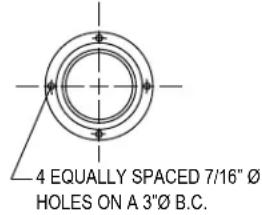
Figure 1
STATIONARY TRI-LEG KETTLES
| MODEL | A | B | C | D | E | F (2") | F (3") | G (2") | G (3") | H | J | K | L |
| KLS-20E | 21[533] | 18[457] | 38[965] | 23.75[629] | 18.5[470] | 14.75[375] | 15.5[395] | 18[457] | 17.5[445] | 14[356] | 21[533] | 60.5[1537] | 16.75[425] |
| KLS-25E | 21[533] | 20.5[521] | 36.75[933] | 23.75[629] | 14.37[365] | 14.75[375] | 15.5[394] | 14.16[360] | 13.66[347] | 9.55[243] | 17.2[437] | 61.22[1555] | 12.41[315] |
| KLS-30E | 24[610] | 20[508] | 38[965] | 27.75[705] | 20[508] | 16[406] | 16.5[419] | 15.75[400] | 15.25[387] | 12.5[318] | 19[483] | 63.5[1613] | 18.3[465] |
| KLS-40E | 26[660] | 22.5[572] | 38[965] | 29.75[756] | 21[533] | 17[432] | 18[457] | 13.5[343] | 13[330] | 9[229] | 17[432] | 65[1651] | 19.9[506] |
| KLS-60E | 29.5[749] | 26[660] | 42[1067] | 33.75[857] | 19[483] | 18[457] | 19.25[489] | 14[356] | 13.5[343] | 11[280] | 17.25[438] | 75[1905] | 23.125[587] |
| KLS-80E | 33[838] | 28[711] | 45[1143] | 36.75[933] | 20.5[521] | 19.5[495] | 20.5[521] | 15[381] | 14.5[368] | 12.75[324] | 18[458] | 81[2058] | 26.25[667] |
| KLS-100E | 35.5[902] | 30[762] | 48[1219] | 40[1016] | 22[559] | 21.5[546] | 22.5[572] | 15[381] | 14.5[368] | 13[330] | 20.5[521] | 87[2210] | 29.438[748] |
ELECTRICAL CHARACTERISTICS
| AMPS PER LINE | ||||||||
| KW | PHASE 208 | V 220V 240 | V 380V 41 | 5V 440V 430V | ||||
| 12 | 1 57.7 | 54.4 50.0 | N/A N/A N/A | N/A | ||||
| 3 33.3 | 31.5 28.9 | 8.2 16.7 N/A | 14.4 | |||||
| 12.6 | 3 N/A N/A N/A | N/A N/A N/A | 16.5* N/A | |||||
| 15 | 1 72.1 | 68.2 62.5 | N/A N/A N/A | N/A | ||||
| 3 41.6 | 39.4 36.1 | 22.8 20.9 N/A | 18.0 | |||||
| 18 | 1 86.5 | 81.8 75.0 | N/A N/A N/A | N/A | ||||
| 3 50.0 | 47.2 43.3 | 27.3 25 N/A | 21.7 | |||||
| 24 3 | 66.6 63.0 | 57.7 36.5 33.4 | N/A 28.9 | |||||
| 33 3 | 91.6 86.6 | 79.4 50.1 45.9 | 39.7 | |||||
* KLS-25E model only
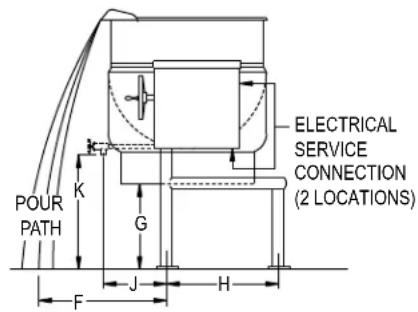
SERVICE CONNECTIONS
| EC | Electrical Connection to be as specified on data plate. |
![SAFETY RELIEF VALVE WALL AIR VENT 2" VALVE: CLOSED 5.13[130] OPENED 6.88[175] 3" VALVE CLOSED 7.88[200] OPENED 10.13[257] OPTIONAL FAUCET ALLOW DIMENSION "D" ADDITIONAL 6[152]](/content/2026/06/1218213/images/619b21d4850d80ca2de720406594b3a02ba033780f71bdcf29f47b128e30cff6.jpg)
DIMENSIONS ARE IN INCHES [MM]
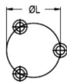
FLANGED FOOT DETAIL
4 EQUALLY SPACED
∅7/16" [11mm] HOLES
ON 3 [76] B.C.
25 GALLON FOOT DETAIL
3 EQUALLY SPACED
07/16" [11MM] HOLES
ON 3-1/8" [80MM] B.C.D.
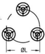
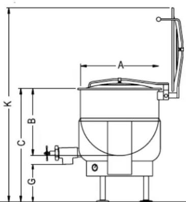
Figure 2
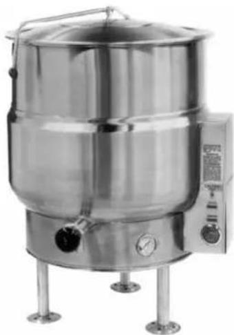
STATIONARY PEDESTAL BASE KETTLES
ELECTRICAL CHARACTERISTICS
| AVAILABLE KW AMPS PER LINE | |||||||||||
| Model Standard Optional kW pH 208V | 220V 240V | 380V 415V | 480V 600V | ||||||||
| KPS-20E 12 n/a | 1231.5 28.9 | 1 57.5 | 54.5 50.0 | - | - | - | - | ||||
| KPS-30E 15 n/a | 3 33.3 | 18.2 16.7 14.4 11.6 | |||||||||
| KPS-40E 18 | 24 | 15 | 1 72.1 | 68.2 62.5 | - | - | - | - | |||
| KPS-60E | 18 | 24, 33 | 3 | 41.6 | 39.4 | 36.1 | 22.8 | 20.9 | 18.0 | 14.5 | |
| KPS-80E 18 | 24, 33 | 18 | 1 86.5 | 81.8 75.0 | - | - | - | - | |||
| KPS-100E | 24 | 33 | 3 | 50.0 | 47.2 | 43.3 | 27.3 | 25.0 | 21.7 | 21.7 | |
| 24 | 3 66.6 | 63.0 57.7 | 36.5 33.4 | 28.9 23.1 | |||||||
| 33 | 3 91.6 | 86.6 79.4 | 50.1 45.9 | 39.7 31.8 | |||||||
DIMENSIONS
| MODELS | A | B | C | D | E | F (2") | F(3") | G(2") | G(3") | H | J | K |
| KPS-20E | 21[533] | 18[457] | 38[965] | 23.75[629] | 18.5[470] | 14.75[375] | 15.5[394] | 18[457] | 17.5[445] | 14[356] | 21[533] | 60[1537] |
| KPS-30E | 24[610] | 20[508] | 38[965] | 27.75[705] | 20[508] | 16[406] | 16.5[419] | 15.75[400] | 15.25[387] | 12.5[318] | 19[483] | 63.5[1613] |
| KPS-40E | 26[660] | 22.5[572] | 38[965] | 29.75[756] | 21[533] | 17[432] | 18[457] | 13.5[343] | 13[330] | 9[229] | 17[432] | 65[1651] |
| KPS-60E | 29.5[749] | 26[660] | 42[1067] | 33.75[857] | 19[483] | 18[457] | 19.25[489] | 14[356] | 13.5[343] | 11[280] | 17.25[438] | 75[1905] |
| KPS-80E | 33[838] | 28[711] | 45[1143] | 36.75[933] | 20.5[521] | 19.5[495] | 20.5[521] | 15[381] | 14.5[368] | 12.75[324] | 18[458] | 81[2058] |
| KPS-100E | 35.5[902] | 30[762] | 48[1219] | 40[1016] | 22[559] | 21.5[546] | 22.5[572] | 15[381] | 14.5[368] | 13[330] | 20.5[521] | 87[2210] |
MINIMUM CLEARANCE
3" (76mm) on sides and back
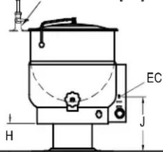
SERVICE CONNECTIONS
EC Electrical Connection to be as specified on data plate.
NOTE
2" VALVE 3" VALVE
CLOSED 5.13 [130] CLOSED 7.88 [200]
OPENED 6.88 [175] OPENED 10.13 [257]
SAFETY
RELIEF

DIMENSIONS ARE IN INCHES [MM]
OPTIONAL FAUCET
ALLOW DIMENSION "D"
ADDITIONAL 6 [152]
PEDESTAL DETAIL
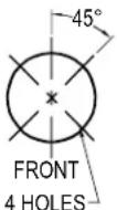
∅7/16 [11MM] EQUALLY SPACED
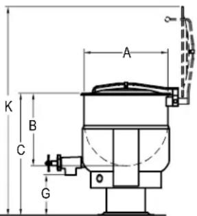
Figure 3
- Select a location to provide drainage directly below the tangent draw-off. Allow sufficient rear clearance from wall for kettle cover to lift upright freely and completely without obstructions.
- Mark hole locations through flanged adjustable feet on KLT-E models. Remove kettle.
- Drill holes on marked hole locations, and insert expansion shields to accommodate 5/16" size lag bolts.
- Reposition kettle. On KLS-__E models level by making necessary adjustments on flanged feet.
- Bolt down kettle and seal with Silastic or other equivalent sealing compound. Sealant must be applied not only to bolt heads but also around flanges or pedestal base making contact with floor surface to fulfill NSF requirements. Wipe off excess sealant immediately.
- A control box with power supply equivalent to electrical
- Rating of kettle should be located conveniently nearby.
- A waterproof electrical connection for power supply to rear of control housing must be provided.
- Ground kettle to terminal provided inside control housing.
- Turn power ON and check for proper operation.
OPERATION
- Check kettle pressure gauge that reading indicates 20-25 vacuum for a cold kettle. If vacuum is insufficient, air venting instructions must be followed. If equipped with draw off valve ensure valve is closed.
- Place kettle power switch in ON position.
- Preheat kettle by turning thermostat knob to '8' and wait until temperature pilot light goes off.
NOTE: Food products with milk or egg base should be placed into cold kettle and then the cooking operation begun. Avoid sudden contact of these food products to hot kettle bowl surface since caking/adhering will occur.
- Place food product into kettle bowl. Close kettle cover.
- Adjust thermostat knob to temperature cooking mode. Setting of 6-7 will provide simmer and 8-10 low to rolling boil.
- Turn both kettle power switch and thermostat knob OFF when cooking has been completed.
- Remove food product by ladling out of kettle bowl or by opening draw-off valve and pouring into a suitable container.

WARNING
DRAW OFF VALVE HAS A VUCANIZED RUBBER COATED STEAM FOR BETTER SEALING. DO NOT OVERTIGHTEN. THIS MAY CAUSE THE RUBBER TO PULL AWAY FROM STEAM AND PERMANENTLY DAMAGE IT.
CLEANING
Your kettle should be cleaned immediately after each use to prevent food residue from drying and adhering too kettle bowl and valve surfaces.
- Turn power supply OFF to kettle
- Rinse inside of kettle thoroughly. Drain kettle by tilting or if equipped wit-h drain valve, open valve and remove all food particles. Close drain valve.
- Using nylon brush, clean kettle with a mild detergent and warm water rinse. Never use steel wool or scouring powder as they will scratch stainless steel. Food adhering excessively to bowl surface may be loosened by allowing water to soak in a bowl at a low temperature setting.
- Open the draw-off to allow soap and water solution to drain.
- By hand, turn large hex nut on draw-off valve counter clockwise until completely disengaged from thread. Grasp valve knob and pullout valve steam and disc slowly.
- Avoid contact of valve disc with hard surfaces since damage to disc may occur and result in valve leakage. Wash the valve stem, disc and handles. Insert nylon brush with detergent into interior of valve body and tangent draw-off tube and brush vigorously.
- Replace valve stem assembly and engage hex nut fully by hand. Flush kettle with clean warm water and leave valve open when kettle is not in use.
- Wipe down exterior of kettle with clean damp cloth.

WARNING
It is NOT RECOMMENDED to use cleaning agents that are corrosive.
Use of cleaning agents that contain chloride, acids or salts are corrosive and may cause pitting and corrosion when used over a period of time; this will reduce the life of the appliance.
Should pitting or corrosion occur this is not covered by warranty.
Follow the recommended cleaning instructions Use detergent, warm water and rinse thoroughly.
NEVER SPRAY WATER INTO ELECTRIC CONTROLS.


Brand : Blodgett
Model : KPS-40E
Category : Aaaa