
TH-FM - Furniture Support Atdec - Free user manual and instructions
Find the device manual for free TH-FM Atdec in PDF.

| Product Type | Furniture Mount (TV/Display Stand) |
| Brand | Atdec |
| Model | TH-FM |
| Maximum Load Capacity | 35 kg (77 lbs) |
| VESA Compatibility | 100-600mm (width) x 100-400mm (height) |
| Tilt Adjustment | -5° to +20° (5° incremental steps) |
| Rotation Limiting | Adjustable via M4x8 grub screw |
| Cable Management | Built-in cable routing |
| Mounting Options | Bolt-through (15-45mm surface) or adhesive |
| Hardware Included | Coach bolts, security nuts, Allen keys, grub screw, mounting brackets, horizontal rail |
| Material | Steel |
| Color | Black (typical) |
| Weight | Approx. 5-7 kg (not specified) |
| Dimensions (Horizontal Rail) | Length sufficient for VESA up to 600mm |
| Safety Features | Locking plates, security nuts |
| Installation Type | Furniture mount (sit-on or bolted) |
| Compatibility | Most flat-screen TVs up to 35 kg |
| Cleaning Instructions | Wipe with dry cloth; no solvents |
| Warranty | Refer to manufacturer |
Frequently Asked Questions - TH-FM Atdec
User questions about TH-FM Atdec
0 question about this device. Answer the ones you know or ask your own.
Ask a new question about this device
Download the instructions for your Furniture Support in PDF format for free! Find your manual TH-FM - Atdec and take your electronic device back in hand. On this page are published all the documents necessary for the use of your device. TH-FM by Atdec.
USER MANUAL TH-FM Atdec
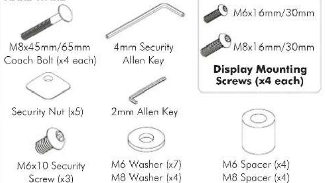
HARDWARE
IMPORTANT INFORMATION:
! IMPORTANT - Install Telehook Furniture Mount as per installation instruction.
! This product supports a maximum load of 35kg (77lbs.).
! This product has a universal mounting hole pattern that suits a broad range of TV's: From 100-600mm in width and 100-400mm in height.
! The manufacturer accepts no responsibility for incorrect installation.
Step 1. Check Components
Check you have received against the component checklist and hardware above.
Step 2. Limit Rotation and Position
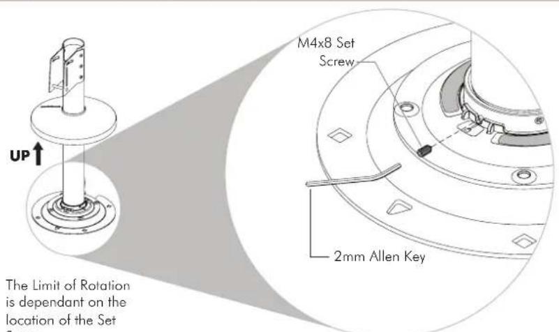
NOTE: Use 2mm Allen Key to remove and insert M4x8 Grub Screw to the desired hole position.

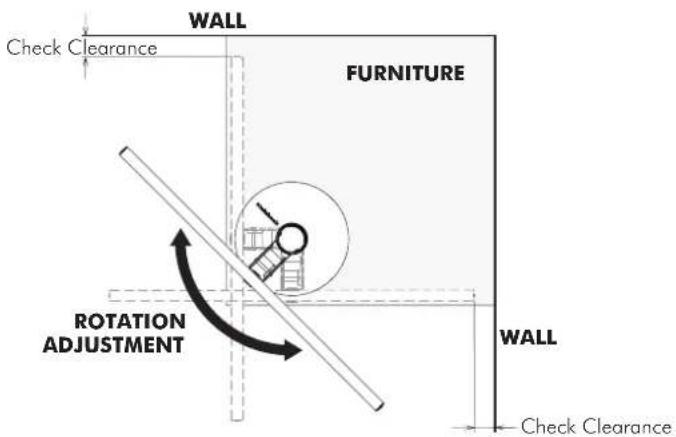
Step 3. Check Space
Before installing your TH-FM check your proposed location has enough space for the amount of rotation you are planning to use.
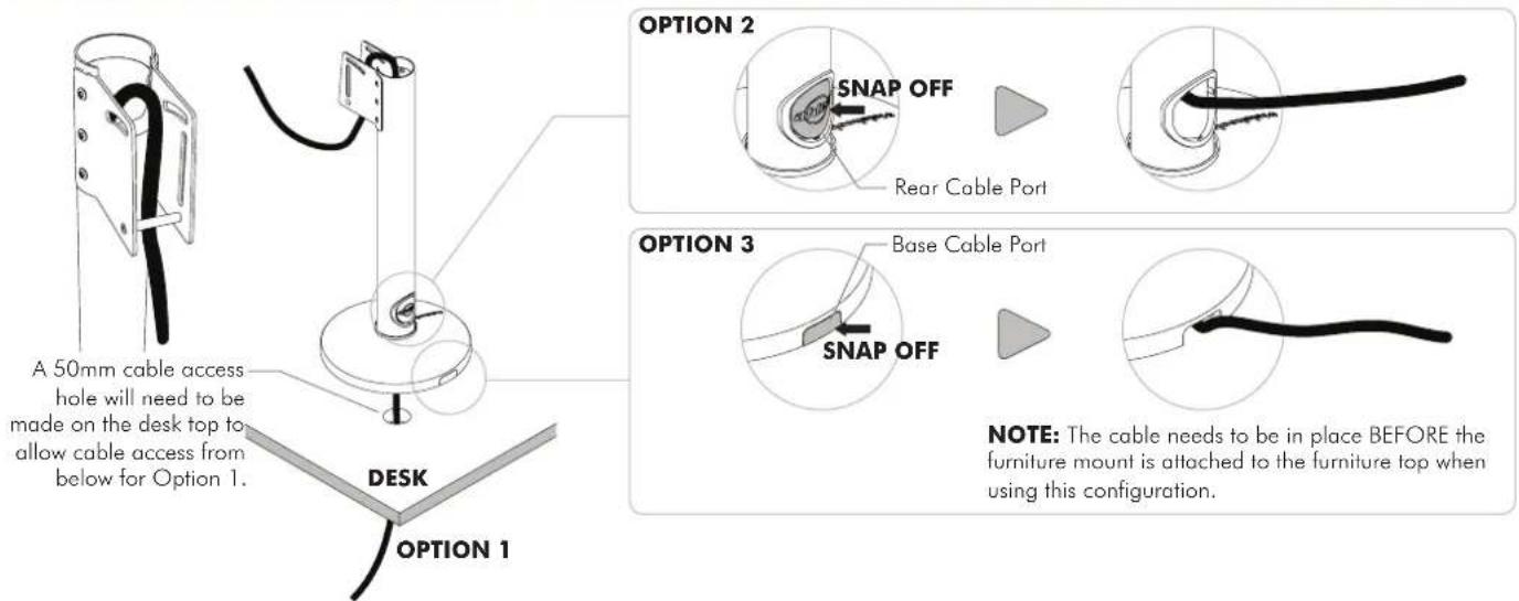
Step 4. Cable Management
Step 5. Locate and Secure the Furniture Mount
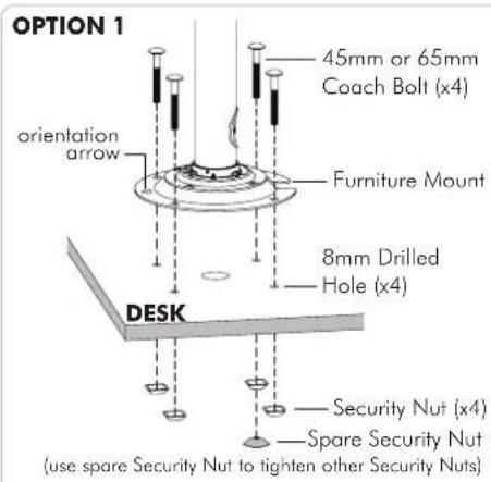
NOTES:
- Use 45mm Coach Bolt for 15-25mm surface thickness and 65mm Coach Bolt for 25mm-45mm surface thickness.
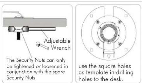
- Remove the spare Security Nut after tightening other Security Nuts. Keep it in a safe place for future usage.
OPTION 2
Atdec recommends a good quality Brand Name contact adhesive. Please follow directions on the product.

NOTE: If Option 2 is preferred to secure your Furniture Mount, all cables need to be in place before the Furniture Mount is attached to the surface.
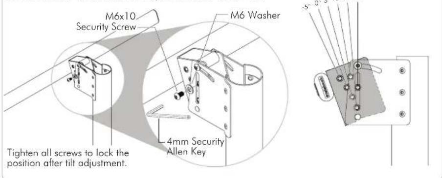
Step 6. Install the Horizontal Rail

Step 7. Tilt Adjustment

OPTION 2: 5° Incremental Tilt Adjustment from -5° to +20°
Step 8. Attach Bracket Mount to Display
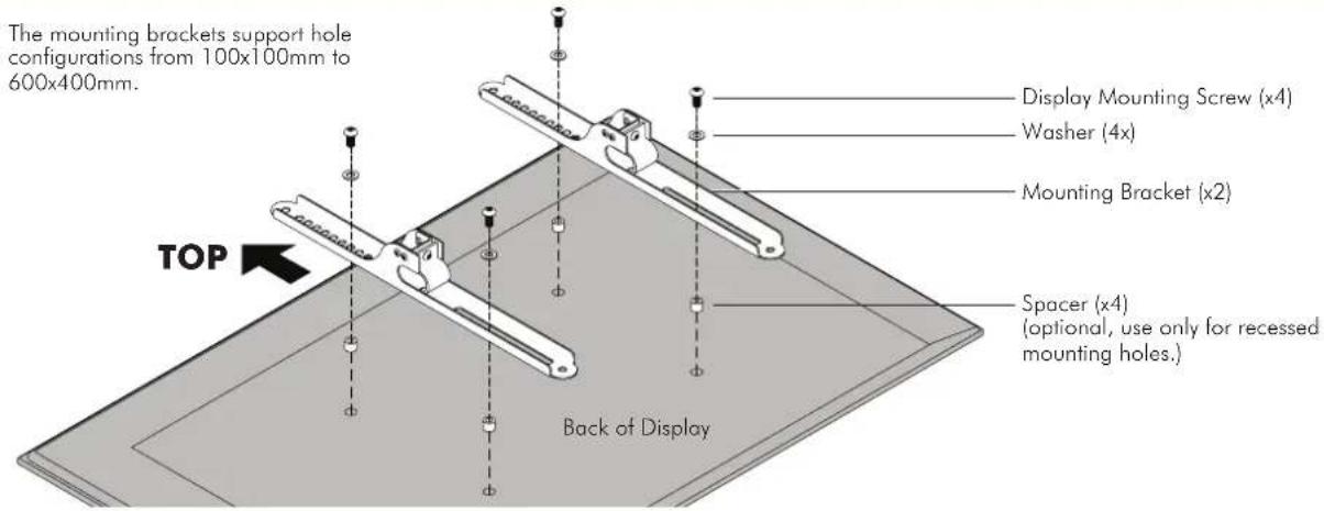
Step 9. Attach Bracket Mount with Display to Horizontal Rail
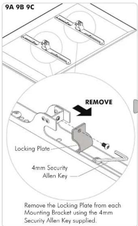

Slide the Display sideways to locate the centre.

Re-attach the Locking Plate from each Mounting Bracket using the 4mm Security Allen Key supplied to secure the Mounting Brackets in place.
Step 10. Insert the Top Cap and Push down Base Cover in place
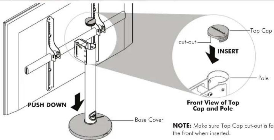
Installation Complete
Brand : Atdec
Model : TH-FM
Category : Furniture Support