TLM-170FR - Monitor DataVideo - Free user manual and instructions
Find the device manual for free TLM-170FR DataVideo in PDF.

User questions about TLM-170FR DataVideo
0 question about this device. Answer the ones you know or ask your own.
Ask a new question about this device
Download the instructions for your Monitor in PDF format for free! Find your manual TLM-170FR - DataVideo and take your electronic device back in hand. On this page are published all the documents necessary for the use of your device. TLM-170FR by DataVideo.
USER MANUAL TLM-170FR DataVideo
WARNINGS AND PRECAUTIONS......4
WARRANTY....5
STANDARD WARRANTY 5
THREE YEAR WARRANTY....5
DISPOSAL....6
- INTRODUCTION....7
FEATURES 7
MODEL TYPES....7
-
ASSEMBLING 8
-
CONNECTIONS AND CONTROLS.... 10
FRONT PANEL....10
REAR PANEL....13
- OSD MENU....14
PICTURE....19
Brightness....19
Contrast 19
Saturation....19
Tint 19
Sharpness 19
HDMI RGB Range.... 19
HDMI EDID.... 19
Color Space 19
Camera Log.... 20
Def. Log.... 20
User Log 20
Gamma....20
HDR....21
Back Light 21
Color Temperature 21
MARKER 21
Center Marker 22
Center Marker Size 22
Aspect Marker 22
Safety Marker 22
Marker Color....23
Aspect MAT 23
Thickness 23
User Marker H1/H2 23
User Marker V1/V2.... 23
FUNCTION 23
Scan 23
Aspect....23
Overscan....24
H/V Delay 24
Check Field.... 25
Zoom....25
Freeze 25
WAVEFORM....25
Waveform 25
Vector 27
Transparency 27
Peaking filter 27
False Color 28
False Color Table.... 29
Exposure 30
Histogram.... 31
Time Code.... 32
AUDIO 33
Volume and Level Meter 33
Audio Vector 33
Audio Vector CH (HDMI) 33
Audio Vector CH (SDI) 33
Audio Left Out.... 33
Audio Right Out 34
SYSTEM....34
Language 34
Color Bar 34
Color Bar Mode 34
OSD Timer 34
OSD Transparency 34
OSD H Position 35
OSD V Position 35
Fan....35
Color Calibration.... 35
Comparison EN.... 35
Reset 35
- COLOR MANAGEMENT SYSTEM – CALIBRATION PROCESS ...... 36
DEVICE SETUP 36
SOFTWARE SETUP.... 38
-
FIRMWARE UPDATE....46
-
DIMENSIONS......48
-
SPECIFICATIONS....49
SERVICE AND SUPPORT .... 52
Disclaimer of Product & Services
The information offered in this instruction manual is intended as a guide only. At all times, Datavideo Technologies will try to give correct, complete and suitable information. However, Datavideo Technologies cannot exclude that some information in this manual, from time to time, may not be correct or may be incomplete. This manual may contain typing errors, omissions or incorrect information. Datavideo Technologies always recommend that you double check the information in this document for accuracy before making any purchase decision or using the product. Datavideo Technologies is not responsible for any omissions or errors, or for any subsequent loss or damage caused by using the information contained within this manual. Further advice on the content of this manual or on the product can be obtained by contacting your local Datavideo Office or dealer.
FCC Compliance Statement
This device complies with part 15 of the FCC rules. Operation is subject to the following two conditions:
- This device may not cause harmful interference, and
- This device must accept any interference received, including interference that may cause undesired operation.
Warnings and Precautions
- Read all of these warnings and save them for later reference.
- Follow all warnings and instructions marked on this unit.
- Unplug this unit from the wall outlet before cleaning. Do not use liquid or aerosol cleaners. Use a damp cloth for cleaning.
- Do not use this unit in or near water.
- Do not place this unit on an unstable cart, stand, or table. The unit may fall, causing serious damage.
- Slots and openings on the cabinet top, back, and bottom are provided for ventilation. To ensure safe and reliable operation of this unit, and to protect it from overheating, do not block or cover these openings. Do not place this unit on a bed, sofa, rug, or similar surface, as the ventilation openings on the bottom of the cabinet will be blocked. This unit should never be placed near or over a heat register or radiator. This unit should not be placed in a built-in installation unless proper ventilation is provided.
- This product should only be operated from the type of power source indicated on the marking label of the AC adapter. If you are not sure of the type of power available, consult your Datavideo dealer or your local power company.
- Do not allow anything to rest on the power cord. Do not locate this unit where the power cord will be walked on, rolled over, or otherwise stressed.
- If an extension cord must be used with this unit, make sure that the total of the ampere ratings on the products plugged into the extension cord do not exceed the extension cord rating.
- Make sure that the total amperes of all the units that are plugged into a single wall outlet do not exceed 15 amperes.
- Never push objects of any kind into this unit through the cabinet ventilation slots, as they may touch dangerous voltage points or short out parts that could result in risk of fire or electric shock. Never spill liquid of any kind onto or into this unit.
- Except as specifically explained elsewhere in this manual, do not attempt to service this product yourself. Opening or removing covers that are marked "Do Not Remove" may expose you to dangerous voltage points or other risks, and will void your warranty. Refer all service issues to qualified service personnel.
- Unplug this product from the wall outlet and refer to qualified service personnel under the following conditions:
a. When the power cord is damaged or frayed;
b. When liquid has spilled into the unit;
c. When the product has been exposed to rain or water;

d. When the product does not operate normally under normal operating conditions. Adjust only those controls that are covered by the operating instructions in this manual; improper adjustment of other controls may result in damage to the unit and may often require extensive work by a qualified technician to restore the unit to normal operation;
e. When the product has been dropped or the cabinet has been damaged;
f. When the product exhibits a distinct change in performance, indicating a need for service.
Warranty
Standard Warranty
- Datavideo equipment is guaranteed against any manufacturing defects for one year from the date of purchase.
- The original purchase invoice or other documentary evidence should be supplied at the time of any request for repair under warranty.
- The product warranty period beings on the purchase date. If the purchase date is unknown, the product warranty period begins on the thirtieth day after shipment from a Datavideo office.
- All non-Datavideo manufactured products (product without Datavideo logo) have only one year warranty from the date of purchase.
- Damage caused by accident, misuse, unauthorized repairs, sand, grit or water is not covered under warranty.
• Viruses and malware infections on the computer systems are not covered under warranty. - Any errors that are caused by unauthorized third-party software installations, which are not required by our computer systems, are not covered under warranty.
- All mail or transportation costs including insurance are at the expense of the owner.
- All other claims of any nature are not covered.
- All accessories including headphones, cables, batteries, metal parts, housing, cable reel and consumable parts are not covered under warranty.
- Warranty only valid in the country or region of purchase.
- Your statutory rights are not affected.
Three Year Warranty
- All Datavideo products purchased after July 1st, 2017 qualify for a free two years extension to the standard warranty, providing the product is registered with Datavideo within 30 days of purchase.

- Certain parts with limited lifetime expectancy such as LCD panels, DVD drives, Hard Drive, Solid State Drive, SD Card, USB Thumb Drive, Lighting, Non-PCIe Card and third party provided PC components are covered for 1 year.
- The three-year warranty must be registered on Datavideo's official website or with your local Datavideo office or one of its authorized distributors within 30 days of purchase.
Disposal

natural_image
Symbol of a trash bin crossed with diagonal lines, no text or labels presentFor EU Customers only - WEEE Marking
This symbol on the product or on its packaging indicates that this product must not be disposed of with your other household waste. Instead, it is your responsibility to dispose of your waste equipment by handing it over to a designated collection point for the recycling of waste electrical and electronic equipment. The separate collection and recycling of your waste equipment at the time of disposal will help to conserve natural resources and ensure that it is recycled in a manner that protects human health and the environment. For more information about where you can drop off your waste equipment for recycling, please contact your local city office, your household waste disposal service or the shop where you purchased the product.

text_image
CECE Marking is the symbol as shown on the left of this page. The letters "CE" are the abbreviation of French phrase "Conformité Européenne" which literally means "European Conformity". The term initially used was "EC Mark" and it was officially replaced by "CE Marking" in the Directive 93/68/EEC in 1993. "CE
Marking" is now used in all EU official documents.
1. Introduction
The TLM-170F offers a FHD 1920 x 1080 LCD Panel which provides a wide viewing angle of 178^ , 300 cd/m² brightness, and 700:1 contrast ratio. It features a 12G SDI input and two HDMI 2.0 inputs with one loop through output allowing connection of up to DCI 4K and Ultra HD video sources.
The TLM-170F is equipped with various functions such as waveform, vector scope, false color filter, histogram, peaking filter, zoom, screen markers, etc. The TLM-170F has two HDR transfer functions which are HLG and SMPTE 2084. The color space includes options such as Rec 709 and DCI P3 Cinema. The TLM -170K is designed specifically for broadcast and field production applications.
Features
- DCI 4K/60p and UHD 4K/60p videos for both input and output
• 17" monitor with FHD (1920 x 1080) LCD display - Supports column (YRGB peak), time code, waveform, vector scope & audio level meter, peaking filter, zoom, pix to pix, overscan, check field, etc
• 12G-SDI video input with loop-through output
• HDMI 4K input with loop-through output
• Time Code Display (LTC/VITC) - Four user-assignable function keys (F1, F2, F3, and F4)
• Safety Marker and Aspect Marker - 700:1 contrast ratio, 300~cd / m^2 brightness
• 178° Horizontal & Vertical wide viewing angle - Individual adjustments of Brightness, Contrast, and Saturation.
• Color Match Conversion with Color Temperature Adjustment
• Front panel Headphone Jacks - Tally light included.
Model Types
| Model | TLM-170F | TLM-170FR | TLM-170FM |
| Image |  | 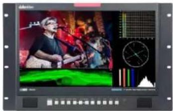 | 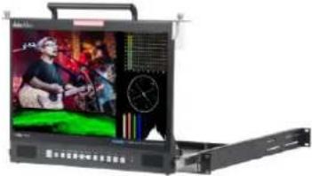 |
| System | Desktop | 7U Rack Mount | 1U Mobile Tray Rack Mount |
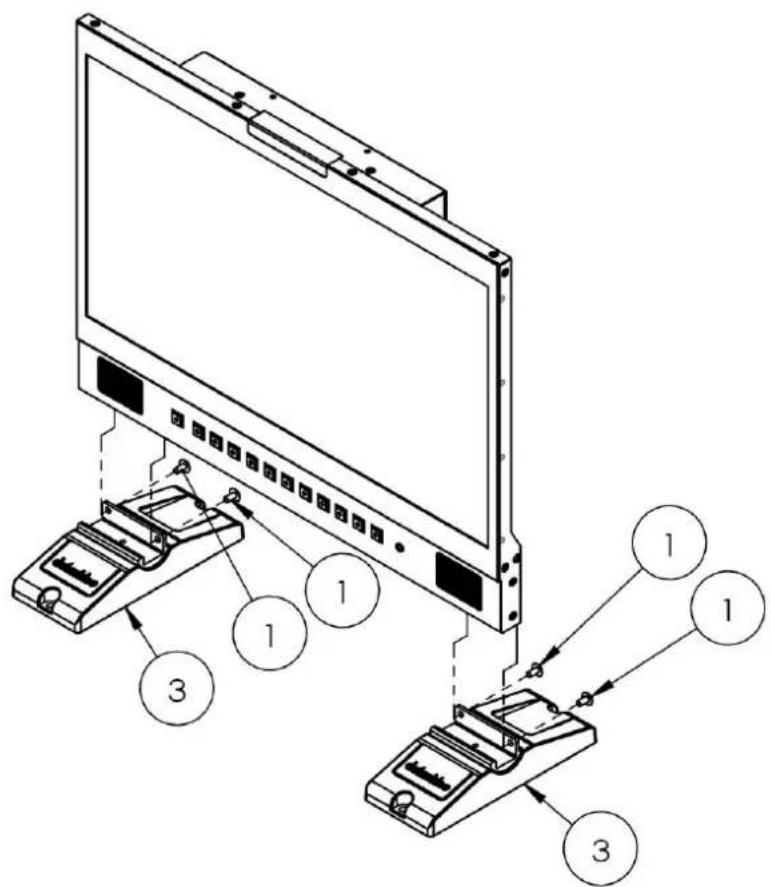
2. Assembling
If you would like to rest the monitor in an upright position on a flat surface, simply use the two riser blocks provided. Follow the steps outlined below to mount the monitor to a flat surface.
Step 1
Make sure you have all the parts listed in the table below in the product package. If you find missing items, please contact local Datavideo office or distributors.
| No. | Part Name | Part No. | Q'ty | Use |
| 1 | Nylok Screw ISO Truss Head M4.0*8m/m Black (RoHS) | G0911D400811 | 4 | Secure the monitor to riser blocks |
| 2 | Truss Head Self-Drilling Screw 5.0*15m/m Nickel Plated | G09111501503 | 4 | Secure riser blocks to the desk |
| 3 | VP-927 TLM-170F Riser Block | G13309271201 | 2 |
Step 2
Insert the monitor to the two riser blocks as shown in the diagram below then secure with truss head nylok screws (G0911D400811).
text_image
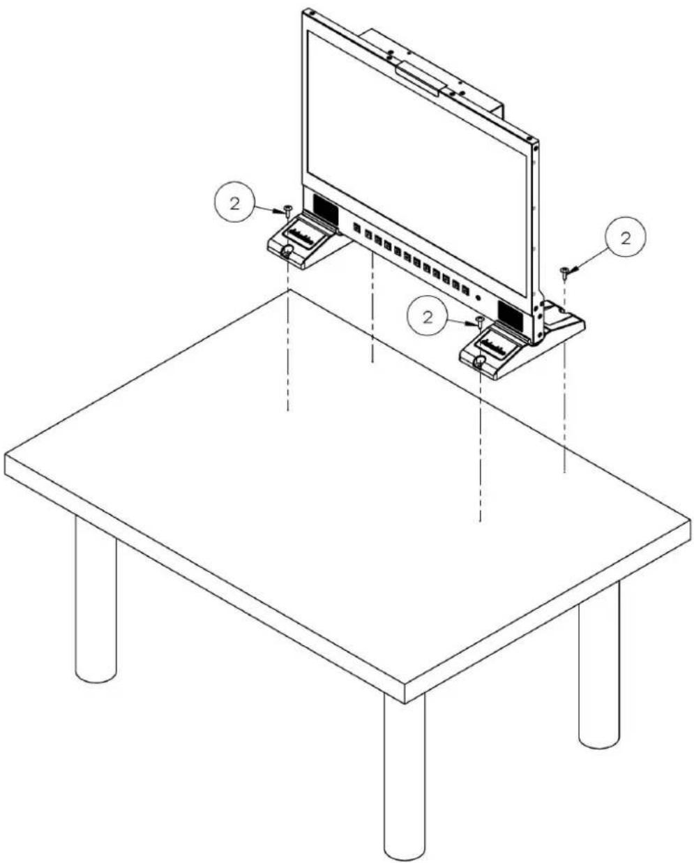
Technical diagram showing two electronic devices connected to a monitor, with labeled components and numbered parts.Step 3
As shown in the diagram below, use the truss head self-drilling screws (G09111501503) to secure the riser blocks to the desk.
text_image
Technical diagram of a monitor setup with labeled components and structural supports3. Connections and Controls
Front Panel

text_image
datavideo Dual Color Tally Light Video Source MENU Activation Return/EXIT Power SDI HOM-1 HOM-2 MENU ← VOL + EXIT F1 F2 F3 F4 ON/OFF Audio Volume Control Shortcut Keys Headphone TOMATOIS 17" SCOPE VIEW PRODUCTION MONITOR| Buttons | Descriptions |
POWER | Power ON/OFFThis button powers the monitor ON/OFF. The main power switch is located at the rear of the TLM-170F. |
SDI | SDI ButtonPress once to enable the SDI video source on the monitor screen.You can connect the loop thru port (seeRear Panel)to a monitor to view the activated input video source.As the SDI video source is activated, the button LED will be turned ON. |
HDMI-1 HDMI-2 | HDMI 1/2 ButtonPress once to enable the HDMI video source on the monitor screen. Please note that the two video sources cannot be enabled at the same time. You can connect the loop thru port (seeRear Panel) to a monitor to view the activated input video source.As the HDMI video source is activated, the corresponding button LED will be turned ON. |
MENU | MENU ButtonPress theMENUbutton to open the OSD menu. Once in the OSD menu, press theMENUbutton to make a selection. |
◄ - VOL + ► | Audio Volume Adjustment ButtonsOnce in the OSD menu, navigate the menu or increase/decrease parameter values using the audio volume adjustment buttons.While NOT in the OSD menu, pressing either one of the audio volume adjustment buttons will open aVolumeslide bar at the bottom of the screen. Then press theMENUbutton to switch to other setting options as listed below:VolumeBrightnessContrastSaturationTintSharpnessExitTo adjust the parameter values, simply press theVol- arrow button to decrease the value and theVol+ arrow button to increase the value. |
EXIT | EXIT ButtonReturn/Exit button |
F1 F2 F2 | F1 – F4 Shortcut KeysPress the F1-F4 shortcut keys to access the corresponding function setting menus. The default function setting menus are shown as follows:F1: ScanF2: WaveformF3: AspectF4: Aspect Marker |
| F3 | Customization of Button FunctionsThe user is allowed to customize or re-assign function setting menus to the F1-F4 shortcut keys. The customization steps are outlined as follows: |
 | |
| F4 | First press and hold one of the shortcut keys (F1-F4) for approximately 3-5 seconds until a pop-up function list appears on the monitor. |
 | Press the left and right arrow keys of the audio volume adjustment buttons to move between options in the pop-up function list.Press the menu button to assign the highlighted function setting menu to the shortcut key selected at step 1.Press the EXIT button to close the pop-up function list. |
| The pop-up function list is shown below:Center MarkerAspect MarkerSafety MarkerOverscanScanAspectColor SpaceGammaCamera LogCheck FieldH/V DelayFreezeColor BarFalse ColorExposureHistogramWaveformVectorTime CodeMuteLevel MeterAudio Vector | |
| Button ResetTo reset F1-F4 buttons to factory defaults, follow the steps outlined as follows:Open the OSD menu, and navigate to SYSTEM.Press the MENU button to enter the SYSTEM sub menu.Move down to the RESET option which is selected by pressing the MENU button.Press either the VOL+ or VOL- button to enable the reset. | |
| Note: The reset function resets all TLM-170F settings. | |
 | Headphone JackOnce the 3.5mm headphone jack is connected, theinternal speaker will be automatically muted. |
 |
Rear Panel

text_image
SDI Input / Output HDMI Input 1 / 2 Loop Thru Output 3.5mm Tally light input socket USB Port DC IN 12V (Phoenix) DC IN 12V (XLR) SDI IN SCI OUT HDMI IN 1 HDMI IN 2 LOOP THRU TALLY IN SERVICE DC = 12V+ POWER IN DC 12V POWER ON OFF ON/OFF Switch| Ports | Descriptions |
| 3.5mm Tally Light Input | Tally light input. The tip, ring and sleeve of the phone jack should be connected to tally red, tally green and the ground. |
| Loop Thru Output | A loop thru output of SDI and HDMI inputs. |
| HDMI Input 1/2 | Connect HDMI video and audio source devices.HDMI 1: YUV420 not supportedHDMI 2: YUV420 supported |
| USB 2.0 Port (SERVICE) | For firmware upgrade only; see Firmware Update for more information about firmware upgrade. |
| SDI Input / Output | 1 SDI input/output pair |
| DC IN 12V | 12 V power input (XLR/Phoenix Terminal) |
| Power ON/OFF Switch | TLM-170F's main power ON/OFF switch |
4. OSD MENU
The TLM-170F can be set up using an OSD menu system. To display the OSD menu press the MENU button. This menu system is navigated using the Left / Right buttons. The Left / Right buttons are also used to change parameter values. Press the MENU button to select an option and the EXIT button to close the OSD menu.
| Main Options | Sub Options | Parameters | ||
| Picture | Brightness | 0 – 100 | ||
| Contrast | 0 – 100 | |||
| Saturation | 0 – 100 | |||
| Tint | 0 – 100 | |||
| Sharpness | 0 – 100 | |||
| HDMI RGB Range | Full | |||
| Limited | ||||
| HDMI EDID | 2K | |||
| 4K | ||||
| Color Space | DCI-P3 | |||
| EBU | ||||
| Rec709 | ||||
| SMPTE-C | ||||
| Native | ||||
| Camera Log | Off | |||
| Def. Log | ||||
| User Log | ||||
| Def. Log | SLog2ToLC-709 | |||
| SLog2ToLC-709TA | ||||
| SLog2ToSLog2-709 | ||||
| SLog2ToCine+709 | ||||
| SLog3ToLC-709 | ||||
| SLog3ToLC-709TA | ||||
| SLog3ToSLog2-709 | ||||
| SLog3ToCine+709 | ||||
| ArriLogCTo709 | ||||
| ArriLogCToP3DCI | ||||
| ClogTo709 | ||||
| VLogToV709 | ||||
| JLog To709HLG | ||||
| JLog To709PQ | ||||
| Z7 NLogTo709 | ||||
| D780 NLogTo709 | ||||
| User Log | No Data | |||
| User 1 | ||||
| User 2 | ||||
| User 3 | ||||
| User 4 | ||||
| User 5 | ||||
| User 6 | ||||
| Gamma | Off | |||
| 1.8 | ||||
| 2.0 | ||||
| 2.2 | ||||
| 2.35 | ||||
| 2.4 | ||||
| 2.6 | ||||
| 2.8 | ||||
| HDR | Off | |||
| ST 2084 300 | ||||
| ST 2084 1000 | ||||
| ST 2084 10000 | ||||
| HLG | ||||
| Back Light | 0 – 100 | |||
| Color Temperature | 3200°K | |||
| 5500°K | ||||
| 6500°K | ||||
| 7500°K | ||||
| 9300°K | ||||
| User Color | Red Gain | 0 – 255 | ||
| Green Gain | 0 – 255 | |||
| Blue Gain | 0 – 255 | |||
| Red Offset | 0 – 511 | |||
| Green Offset | 0 – 511 | |||
| Blue Offset | 0 – 511 | |||
| Marker | Center Marker | ON | ||
| OFF | ||||
| Center Marker Size | Small | |||
| Middle | ||||
| Large | ||||
| Aspect Marker | OFF | |||
| 16:9 | ||||
| 1.85:1 | ||||
| 2.35:1 | ||||
| 4:3 | ||||
| 3:2 | ||||
| 2.0X | ||||
| 2.0X MAG | ||||
| Grid | ||||
| User | ||||
| Safety Market | OFF | |||
| 95% | ||||
| 93% | ||||
| 90% | ||||
| 88% | ||||
| 85% | ||||
| 80% | ||||
| Marker Color | Red | |||
| Green | ||||
| Blue | ||||
| White | ||||
| Black | ||||
| Aspect Mat | OFF | |||
| 1 | ||||
| 2 | ||||
| 3 | ||||
| 4 | ||||
| 5 | ||||
| 6 | ||||
| 7 | ||||
| Thickness | 1 | |||
| 2 | ||||
| 3 | ||||
| 4 | ||||
| 5 | ||||
| 6 | ||||
| 7 | ||||
| 8 | ||||
| 9 | ||||
| 10 | ||||
| 11 | ||||
| 12 | ||||
| 13 | ||||
| 14 | ||||
| 15 | ||||
| User Marker H1 | 1-3840 | |||
| User Marker H2 | 1-3840 | |||
| User Marker V1 | 1-2160 | |||
| User Marker V2 | 1-2160 | |||
| Function | Scan | Zoom | ||
| Aspect | ||||
| Pixel to Pixel | ||||
| Aspect | Full | |||
| 16:9 | ||||
| 1.85:1 | ||||
| 2.35:1 | ||||
| 4:3 | ||||
| 3:2 | ||||
| 2.0X | ||||
| 2.0X MAG | ||||
| Overscan | OFF | |||
| ON | ||||
| H/V Delay | Off | |||
| H | ||||
| V | ||||
| H/V | ||||
| Check Field | OFF | |||
| Red | ||||
| Green | ||||
| Blue | ||||
| Mono | ||||
| Zoom | 90% | |||
| 80% | ||||
| 70% | ||||
| 60% | ||||
| 50% | ||||
| 40% | ||||
| 30% | ||||
| 20% | ||||
| 10% | ||||
| Freeze | OFF | |||
| ON | ||||
| Waveform | Waveform | Multi | ||
| Y | ||||
| YCbCr | ||||
| RGB | ||||
| OFF | ||||
| Vector | OFF | |||
| ON | ||||
| Transparency | 50% | |||
| 25% | ||||
| OFF | ||||
| Peaking | OFF | |||
| ON | ||||
| Peaking Color | Red | |||
| Green | ||||
| Blue | ||||
| White | ||||
| Black | ||||
| Peaking Level | 0 – 100 | |||
| False Color | OFF | |||
| Default | ||||
| Spectrum | ||||
| ARRI | ||||
| RED | ||||
| False Color Table | OFF | |||
| ON | ||||
| Exposure | OFF | |||
| ON | ||||
| Exposure Level | 50 – 100 IRE | |||
| Histogram | OFF | |||
| Y | ||||
| RGB | ||||
| Color | ||||
| Time Code (SDI) | OFF | |||
| LTC | ||||
| VITC | ||||
| Audio | Volume | 0 – 100 | ||
| Level Meter | OFF | |||
| ON | ||||
| Audio Vector | OFF | |||
| ON | ||||
| Audio Vector CH (HDMI) | CH 1/2 | |||
| CH 3/4 | ||||
| CH 5/6 | ||||
| CH 7/8 | ||||
| Audio Vector CH (SDI) | CH 1/2 | |||
| CH 3/4 | ||||
| CH 5/6 | ||||
| CH 7/8 | ||||
| CH 9/10 | ||||
| CH 11/12 | ||||
| CH 13/14 | ||||
| CH 15/16 | ||||
| Audio Left Out | CH1 – 16 (SDI) | |||
| CH 1 – 8 (HDMI) | ||||
| Audio Right Out | CH1 – 16 (SDI) | |||
| CH 1 – 8 (HDMI) | ||||
| System | Language | English | ||
| Traditional Chinese | ||||
| Simplified Chinese | ||||
| Color Bar | OFF | |||
| 100% | ||||
| 75% | ||||
| Color Bar Mode | Rec601 | |||
| Rec709 | ||||
| BT2020 | ||||
| OSD Timer | 10s | |||
| 20s | ||||
| 30s | ||||
| OSD Transparency | OFF | |||
| 25% | ||||
| 50% | ||||
| OSD H Position | 0 – 100 | |||
| OSD V Position | 0 – 100 | |||
| Fan | Auto | |||
| ON | ||||
| OFF | ||||
| Color Calibration | OFF | |||
| ON | ||||
| Comparison En | OFF | |||
| Gamma&HDR | ||||
| Color Space | ||||
| Camera Log | ||||
| Reset | OFF | |||
| ON | ||||
Picture
The TLM-170F allows you to adjust the basic image settings such as the brightness, contrast, saturation, tint and sharpness.
Advanced settings are HDMI RGB range, color space, gamma correction, back light mode, back light level, and color temperature.
Brightness
Adjust the brightness of the screen from 0 - 100.
Contrast
Adjust the contrast of the screen from 0 - 100.
Saturation
Adjust the saturation of the screen from 0 - 100.
Tint
Adjust the tint of the screen from 0 - 100.
Sharpness
Adjust the sharpness of the screen from 0 - 100.
HDMI RGB Range
This set the HDMI RGB Range.
RGB Full (0-255): PC Monitor
RGB Limited (16-235): Standard or HD TVs
HDMI EDID
The EDID learning function is only used when you experience any failures in playing audio and video correctly. You will be able to force the TLM-170F's receiving resolution by setting the EDID to either 2K or 4K so that the connected HDMI source outputs the maximum resolution defined in EDID.
Color Space
Select an option from the list below to provide details of the color primaries for interpretation of XYZ color space.
- EBU
EBU is another RGB color space encompassing 72% of the NTSC color space. EBU stands for the European Broadcasting Union which develops technical standards and regulations for broadcasting. DTV standards in Taiwan are developed based on the EBU standards.
- REC709
REC709 is the standard camera encoding color space for HDTV established by International Telecommunication Union in 1990.
- SMPTE-C
SMPTE-C is the current color standard for broadcasting in America.
- Native
Camera Log
The Camera Log allows you to enable either the connected camera's Log setting (Def. Log) or the user defined log (.cube file generated by CMS software) imported into the TLM-170F.
Def. Log
Rec709 is a color space that produces images that are very normal and realistic with a good amount of contrast and saturation. Log footage recorded on cameras is normally colorless so in order to color grade your Log footage with the Rec709 color space, you can select the appropriate LUT from the list below.
| SLog2ToLC-709 | Sony Log format to Rec709 |
| SLog2ToLC-709TA | |
| SLog2ToSLog2-709 | |
| SLog2ToCine+709 | |
| SLog3ToLC-709 | |
| SLog3ToLC-709TA | |
| SLog3ToSLog2-709 | |
| SLog3ToCine+709 | |
| ArriLogCTo709 | Arri Log format to Rec709 |
| ArriLogCToP3DCI | |
| ClogTo709 | Canon Log format to Rec709 |
| VLogToV709 | Panasonic Log (Varicam) format to Rec709 |
| JLog To709HLG | JVC Log format to Rec709 |
| JLog To709PQ | |
| Z7 NLogTo709 | Nikon Log format to Rec709 |
| D780 NLogTo709 |
User Log
Save color calibration data generated using Light Illusion's CMS software in .cube files.
Note: Filming with log allows you to view various color grading generated using different logs on the monitor.
Gamma
This sets the gamma correction for the source of input; the smaller the gamma, the brighter the screen and vice versa.
- OFF
• 1.8 (MAC OS)
• 2.0
• 2.2 (Windows)
• 2.35
• 2.4
• 2.6
• 2.8
Notes:
Gamma2.2 is used widely for various applications, providing highlight and shadow enhancement or defining a midtone.
Gamma2.4 is recommended for high quality TV program production and REC. 709 color space. Gamma2.6 is the gamma standard for Digital Cinema Initiative (DCI) and movie filming.
HDR
HDR is a new TV video standard that generates higher contrast and wide-gamut images and therefore, an HDR monitor is capable of displaying more colors and details of an image than the regular ones. The TLM-170F offers two HDR transfer functions listed as follows:
- ST 2084 or Perceptual Quantizer is able to represent luminance levels of 300, 1000 and 10000 cd/m².
- HLG stands for Hybrid Log-Gamma which is another HDR transfer function.
Back Light
Adjust the back light level from 0 - 100.
Color Temperature
Select a color temperature for your scene. Color temperatures available on the TLM-170F are listed as follows:
- 3200°K
- 5500°K (Desktop publishing or printing)
• 6500°K (Usually for ordinary PC use) - 7500°K
- 9300°K (TV pictures)
- User Color
Note: Selection of the User Color mode allows you to manually set the color temperature by adjusting the Red Gain, Green Gain, Blue Gain, Red Offset, Green Offset and Blue Offset.
Marker
Aspect ratio is a crucial element in video shooting and it is defined as the proportion of the width and height of any image. You can use different aspect ratios in your video. Therefore, in order to know what will be in frame at different aspect ratios, during shooting, you can turn on the TLM-170F's aspect marker (a.k.a. guide frame) so that you can record the entire screen while still knowing where the cut-off will be by putting a mat over it.
Center Marker
The Center Marker, if turned on, will place a crosshair in the middle of the screen.
Center Marker Size
The Center Marker size can be set to small, medium or large.
Aspect Marker
Sets the aspect marker display at the aspect ratio selected from the list below:
- OFF
• 16:9
• 1.85:1
• 2.35:1
• 4:3
• 3:2 - 2.0X
- Grid
- User
- 2.0X MAG

natural_image
Bird in flight with wings spread across a grassy field under a cloudy sky (no text or symbols visible)2.35:1

natural_image
Bird in flight over a grassy landscape with mountains in the background (no text or symbols visible)1.85:1

natural_image
Bird in flight with wings spread across a mountainous landscape (no text or symbols visible)16:9

natural_image
Bird in flight over a grassy landscape with hills in the background (no text or symbols visible)4:3

natural_image
A bird in flight with wings spread across a green landscape under a cloudy sky (no text or symbols visible)3:2
Safety Marker
This sets the safety zone display, which is the standard viewing range of the recorded video.
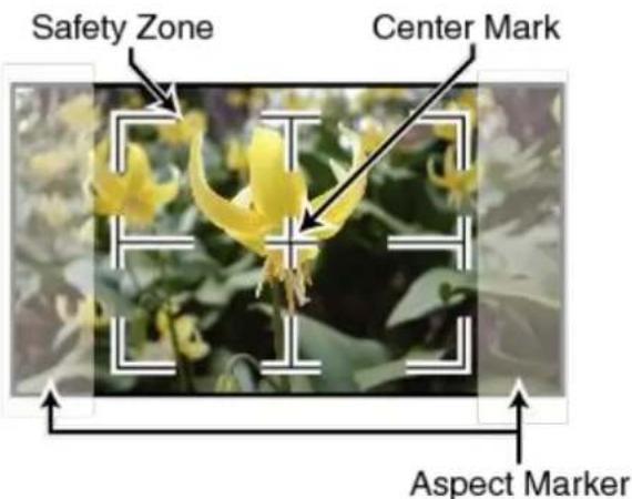
text_image
Safety Zone Center Mark Aspect MarkerThe options are listed as follows:
- OFF
• 95%
• 93%
• 90%
• 88%
• 85%
• 80%
Marker Color
The user is also allowed to apply different colors to the aspect marker. The five available marker colors are Red, Green, Blue, White and Black.
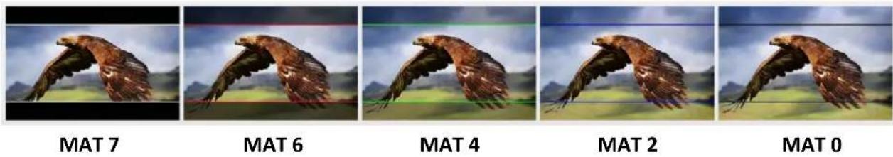
Aspect MAT
This sets the transparency of the mat placed over the cutoff at the select aspect ratio. Select from 0 to 7 with 7 being an opaque mat and 0 offering the highest transparency.
Thickness
This sets the aspect marker thickness ranging from 1 to 15.
User Marker H1/H2
This adjusts the marker's horizontal position.
Increasing the value moves the marker to the right and decreasing the value moves the marker to the left.
User Marker V1/V2
This adjusts the marker's vertical position.
Increasing the value moves the marker up and decreasing the value moves the marker down.
Function
This allows the user to set advanced settings for the TLM-170F, such as the scan mode, the aspect ratio, underscan mode, H/V delay, check field, zoom, and etc. Details of how these functions can be configured are described as follows:
Scan
This sets the Scan mode of the TLM-170F.
Zoom: Enlarge the original image according to the zoom ratio of the TLM-170F.
Aspect: Display the image according to the aspect ratio of the TLM-170F.
Pixel to Pixel: Display the original image resolution without scaling to match a certain resolution or an aspect ratio. For example, when the resolution of the input video is 1920x1080 but the monitor's resolution is only 1280x800, only area equivalent to 1280x800 out of 1920x1080 will be displayed.
Aspect
The aspect control allows you to manually set the aspect ratio of the monitor. You should choose the aspect ratio of your screen to match that of the input video in order to achieve the best
viewing experience. Views of different aspect ratios on the TLM-170F are shown in the diagram below.
Note: Aspect ratio control is disabled if the scan mode is set to pixel to pixel.

natural_image
A bird in flight with brown wings spread across a green hillside under a cloudy sky (no text or symbols visible)full screen

natural_image
A bird in flight over a green landscape with distant mountains under a cloudy sky (no text or symbols visible)2.35:1
natural_image
A bird in flight with wings spread across a grassy landscape under a cloudy sky (no text or symbols visible)1.85:1

natural_image
A bird in flight with brown wings spread across a green hillside under a cloudy sky (no text or symbols visible)16:9

natural_image
A bird in flight with wings spread across a grassy landscape under a cloudy sky (no text or symbols visible)4:3

natural_image
A bird in flight with wings spread across a grassy landscape under a cloudy sky (no text or symbols visible)3:2
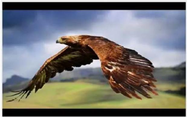
Overscan
If enabled, the image rendered on the display will be larger than the physical area of the screen, creating a cropped image on the monitor screen.
H/V Delay
Used to monitor the blanking area for H sync and V sync.
In H delay mode, the horizontal sync is delayed so that the horizontal blanking period is displayed on the screen.
In V delay mode, the vertical sync is delayed so that the vertical blanking period is displayed on the screen.
In H/V delay mode, both horizontal and vertical syncs are delayed, resulting in both horizontal and vertical blanking periods being shown on the screen.
Note: H/V Delay is disabled if the scan mode is set to pixel to pixel.
Check Field
The check field function offers the user Red-Only, Green-Only, Blue-Only and Mono modes for screen calibration should you require them.

natural_image
Four-panel image showing birds in flight against a cloudy sky, with a circular logo containing the letters 'R', 'G', and 'B' in the center.First turn on the color bar, then turn on the single color mode in the check field as this allows you to do the screen calibration by adjusting the brightness, contrast, saturation, tint and sharpness.
Zoom
The zoom function allows you to enlarge the image by a certain percentage (10 - 90%).
Note: Zoom control is disabled if the scan mode is set to pixel to pixel.
Freeze
The monitor's screen freezes once enabled.
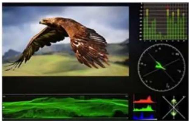
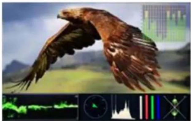
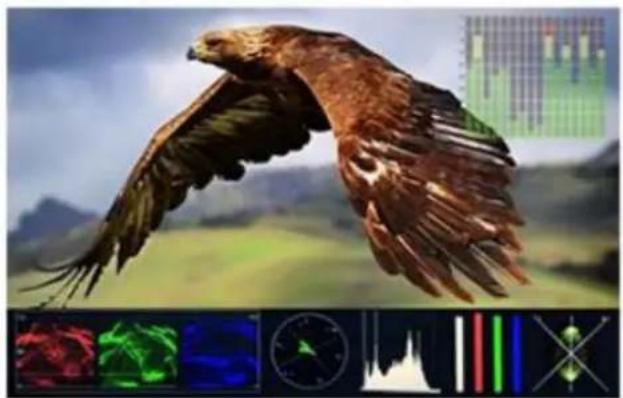
Waveform
The TLM-170F also allows the user to display the image alongside with different monitoring waveforms such as the waveform, vector scope, histogram and audio level meter.
Image quality can be improved using tools such as peaking filter, false color and zebras.
Waveform
The TLM-170F offers users different waveform options listed as follows:
- Muilt (vector scope, YCbCr waveform monitoring, histogram and audio meter)
• Y (Y waveform monitoring)
• YCbCr (YCbCr waveform monitoring)
- RGB (RGB waveform monitoring and histogram)
- Off
natural_image
Composite image showing a bird in flight over rolling hills, overlaid with a financial chart and compass (no readable text or symbols)Multi

natural_image
Illustration of a bird in flight over green grass with mountain background (no text or symbols)Y
natural_image
Illustration of a bird in flight over a green landscape with abstract background elements (no text or symbols)YCbCr
natural_image
Illustration of a bird in flight with landscape background, overlaid with a financial chart and multiple colored data visualizations (red, green, blue) at the bottom.RGB
Note: If Waveform is set to Multi, the Histogram is enabled by default.
Vector Scope

text_image
R Mg YL G Cycolor in the image is very saturated.
The vector scope is used to measure the color information such as Hue and Saturation in a video image.
Note: For color bars, the vector scope works with 100% color bars and 75% color bars with a 75% white level.
Hue: The color markers are red, magenta, blue, cyan, green, and yellow. The proximity a signal to one of the markers tells you what color it is.
Saturation: A vectorscope shows you how saturated your color is and how far away the signal is from the center indicates how saturated the color is. For example, if the color is close to one of those boxes, then that means that
Intersecting lines: The line going up towards the yellow and red colors is the skin tone line on which the skin color should fall regardless of the person's race.
Waveform Monitoring
Waveform monitoring consists of RGB and YCbCr waveforms which are used to measure the brightness, luminance and chroma of a video signal as shown in the diagram below.

Waveform monitoring not only warns the user of out-of-range conditions such as overexposure but also serves as a good tool for color correction and white and black balance.
Vector
This enables/disables the vector scope.
Transparency
This selects the transparency of the waveform and vector scope.
- 50% blend effect
- 25% blend effect
- Off:Opaque
Peaking filter
The peaking filter, once enabled, will place color lines on edges of the subject of the focus in the image. This function works well if the subject of the focus is correctly exposed for high contrast. Red, Green, Blue, White and Black are the five available outline colors on the TLM-170F.
The Peaking Level determines the sensitivity of the filter. Setting the peaking level to a high value means more areas will be highlighted including lower contrast areas. If the peaking level is set to a low value, then only areas of high contrast will be highlighted.
The diagram below illustrates images with peaking filter applied to the subject of the focus. Note the different colors of the outline in each picture.

natural_image
A bird in flight with wings spread across a green field under a cloudy sky (no text or symbols visible)
natural_image
A bird in flight with vibrant green and brown wings against a blurred yellow landscape background (no text or symbols visible)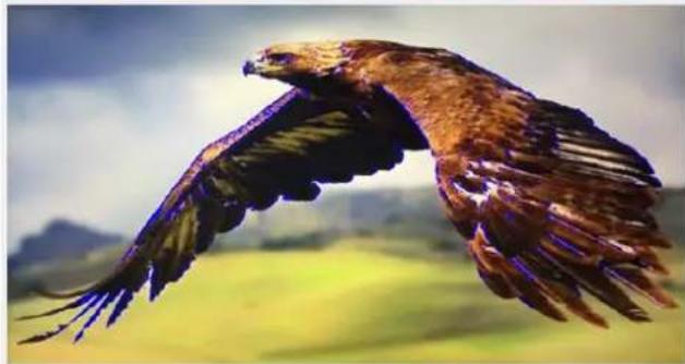
natural_image
A bird in flight with wings spread across a green field under a cloudy sky (no text or symbols visible)
natural_image
A bird in flight with wings spread across a green field under a cloudy sky (no text or symbols visible)False Color
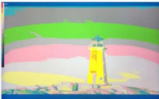
Also known as the exposure assist, once enabled, the false color feature will change colors of the elements of the image based on the brightness value. This allows the user to use the monitor's exposure function to achieve proper exposure without the use of costly external equipment.
To best utilize this feature, you must first understand the color chart below. The color chart is like a color scale. The exposure level is represented by different colors which correspond to the respective luminance of the pixels as displayed on the monitor. The correct exposure ranges from 10 – 100%. Anything below 10% is regarded as underexposed and if exposure exceeds 100%, it is deemed overexposed.
Underexposure and overexposure will lead to loss of details in an image.
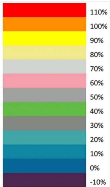
bar
| Category | Value (%) | |---|---| | Top (Red) | 110 | | Top (Orange) | 100 | | Top (Yellow) | 90 | | Top (Light Grey) | 80 | | Top (Pink) | 70 | | Top (Gray) | 60 | | Top (Green) | 50 | | Top (Light Green) | 40 | | Top (Gray) | 30 | | Top (Blue) | 20 | | Top (Cyan) | 10 | | Top (Dark Blue) | 0 | | Bottom (Purple) | -10 |For example, areas with exposure level of 56IRE when applied the false color will be shown as pink color on the monitor. Therefore, as you increase the exposure, that area will change color to grey, then yellow and finally to red if overexposed. Blue indicates underexposure.
An example of an original image with the false color applied is shown on the left of the image below.
natural_image
Colorful lighthouse with yellow sky and pink/gray stripes, no visible text or symbols
natural_image
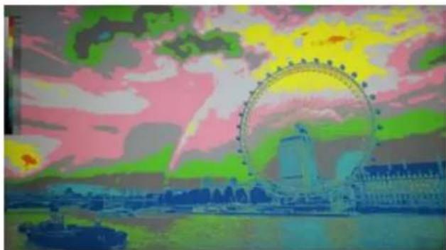
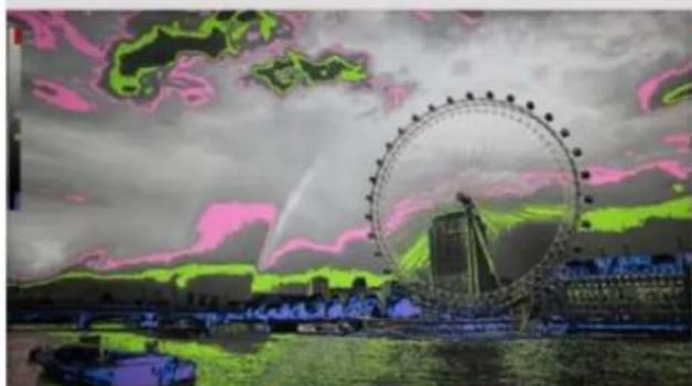
Lighthouse on a rocky outcrop under a clear blue sky, no visible text or symbolsThe four available false color modes are Default (Normal), Spectrum, ARRI and Red, which are illustrated in the diagram below.
natural_image
Illustration of the London Frigate in Paris at sunset, featuring the Ferris wheel and city skyline (no text or symbols)Normal

natural_image
Thermal image of the London Waterfront featuring the Flora Circle and a ship on water under a bright sky (no text or symbols)Spectrum
natural_image
Fleet of the London Water Park with a large Ferris wheel in the background under a dramatic sky (no text or symbols visible)ARRI

natural_image
Night cityscape featuring the London Fringe with a large Ferris wheel and boats on the water under a cloudy sky (no visible text or symbols)RED
False Color Table
This enables/disables false color chart on the screen. A sample of the chart is shown below.

bar
| Range | Value | |---|---| | 100 to 109 IRE | 100 | | 93 to 100 IRE | 93 | | 84 to 93 IRE | 84 | | 77 to 84 IRE | 77 | | 58 to 77 IRE | 58 | | 54 to 58 IRE | 58 | | 47 to 54 IRE | 54 | | 43 to 47 IRE | 47 | | 24 to 43 IRE | 43 | | 15 to 24 IRE | 24 | | 8 to 15 IRE | 15 | | 2 to 8 IRE | 8 | | -7 to 2 IRE | -7 |Exposure
Once the exposure function is turned ON, you will be able to see a zebra pattern superimposed over parts of the image that are exposed to a specific level. In this way, the exposure of the image displayed on the screen can then be adjusted accordingly on the monitor by changing the exposure level (50 – 100 IRE).

text_image
exposure level 0 1 2 3 4 1 2 3 4 exposure level 50Histogram
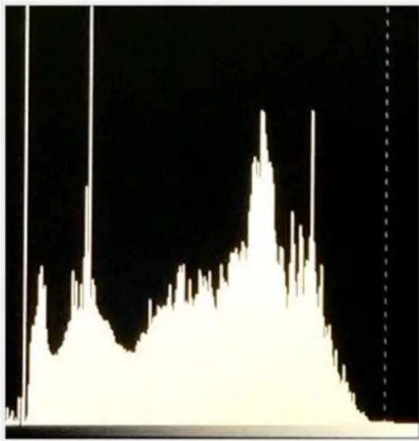
The histogram is a great tool that helps you to improve the overall exposure of the image.
Y (Luminosity)
The Y or luminosity histogram is a graph that describes the human-eye perceived brightness distribution within an image.
To produce the luminosity histogram, first break an image into individual pixels, then each pixel is converted so that it becomes a luminosity based on a weighted average of the three colors at that pixel. The green, red, and blue channels account for 59%, 30% and 11% of the perceived luminosity respectively. This is because human eye is more sensitive to green light than it is to blue or red light. Finally the luminosity histogram is produced by counting how many pixels are at each brightness level as shown in the diagram below.
line
| Time | Signal Intensity | |------|------------------| | 0 | 0.0 | | 1 | 0.5 | | 2 | 1.2 | | 3 | 2.8 | | 4 | 4.5 | | 5 | 6.1 | | 6 | 7.9 | | 7 | 9.3 | | 8 | 10.7 | | 9 | 12.2 | | 10 | 13.8 | | 11 | 15.4 | | 12 | 17.1 | | 13 | 18.9 | | 14 | 20.6 | | 15 | 22.3 | | 16 | 24.0 | | 17 | 25.7 | | 18 | 27.4 | | 19 | 29.1 | | 20 | 30.8 | | 21 | 32.5 | | 22 | 34.2 | | 23 | 35.9 | | 24 | 37.6 | | 25 | 39.3 | | 26 | 41.0 | | 27 | 42.7 | | 28 | 44.4 | | 29 | 46.1 | | 30 | 47.8 | | 31 | 49.5 | | 32 | 51.2 | | 33 | 52.9 | | 34 | 54.6 | | 35 | 56.3 | | 36 | 58.0 | | 37 | 59.7 | | 38 | 61.4 | | 39 | 63.1 | | 40 | 64.8 | | 41 | 66.5 | | 42 | 68.2 | | 43 | 69.9 | | 44 | 71.6 | | 45 | 73.3 | | 46 | 75.0 | | 47 | 76.7 | | 48 | 78.4 | | 49 | 80.1 | | 50 | 81.8 | | 51 | 83.5 | | 52 | 85.2 | | 53 | 86.9 | | 54 | 88.6 | | 55 | 90.3 | | 56 | 92.0 | | 57 | 93.7 | | 58 | 95.4 | | 59 | 97.1 | | 60 | 98.8 | | 61 | 100.5 | | 62 | 102.2 | | 63 | 103.9 | | 64 | 105.6 | | 65 | 107.3 | | 66 | 109.0 | | 67 | 110.7 | | 68 | 112.4 | | 69 | 114.1 | | 70 | 115.8 | | 71 | 117.5 | | 72 | 119.2 | | 73 | 120.9 | | 74 | 122.6 | | 75 | 124.3 | | 76 | 126.0 | | 77 | 127.7 | | 78 | 129.4 | | 79 | 131.1 | | 80 | 132.8 | | 81 | 134.5 | | 82 | 136.2 | | 83 | 137.9 | | 84 | 139.6 | | 85 | 141.3 | | 86 | 143.0 | | 87 | 144.7 | | 88 | 146.4 | | 89 | 148.1 | | 90 | 149.8 | | 91 | 151.5 | | 92 | 153.2 | | 93 | 154.9 | | 94 | 156.6 | | 95 | 158.3 | | 96 | 160.0 | | 97 | 161.7 | | 98 | 163.4 | | 99 | 165.1 | | 100 | 166.8 |RGB
The RGB histogram is a graph that represents the overall brightness of the entire image.
In any digital image, each individual color is made by combining red, green and blue lights with each light represented by its brightness level ranging from 0 to 255. Therefore every color produced in this way has a specific brightness value based on mixes of red, green and blue throughout the image and these brightness values of all the different colors in an image are represented in a histogram which is known as the RGB histogram.
On the TLM-170F, the RGB histogram is shown with the color overlay as depicted in the diagram below.

bar
| Category | Value | | -------- | ----- | | Blue | 120 | | Cyan | 80 | | Green | 90 | | Yellow | 150 | | Red | 180 | | White | 70 |Color
By setting the histogram to color, you will see one red histogram, one green histogram and one blue histogram. Each color histogram is basically a representation of how that color's intensity is distributed throughout an image, allowing you to evaluate the brightness and exposure of that individual color channel. See the diagram below for an example of the color histogram.

area
| Time | Red Area | Green Area | Blue Area | |------|----------|------------|-----------| | 0 | 0 | 0 | 0 | | 1 | 0 | 0 | 0 | | 2 | 0 | 0 | 0 | | 3 | 0 | 0 | 0 | | 4 | 0 | 0 | 0 | | 5 | 0 | 0 | 0 | | 6 | 0 | 0 | 0 | | 7 | 0 | 0 | 0 | | 8 | 0 | 0 | 0 | | 9 | 0 | 0 | 0 | | 10 | 0 | 0 | 0 | | 11 | 0 | 0 | 0 | | 12 | 0 | 0 | 0 | | 13 | 0 | 0 | 0 | | 14 | 0 | 0 | 0 | | 15 | 0 | 0 | 0 | | 16 | 0 | 0 | 0 | | 17 | 0 | 0 | 0 | | 18 | 0 | 0 | 0 | | 19 | 0 | 0 | 0 | | 20 | 0 | 0 | 0 | | 21 | 0 | 0 | 0 | | 22 | 0 | 0 | 0 | | 23 | 0 | 0 | 0 | | 24 | 0 | 0 | 0 | | 25 | 0 | 0 | 0 | | 26 | 0 | 0 | 0 | | 27 | 0 | 0 | 0 | | 28 | 0 | 0 | 0 | | 29 | 0 | 0 | 0 | | 30 | 0 | 0 | 0 | | 31 | 0 | 0 | 0 | | 32 | 0 | 0 | 0 | | 33 | 0 | 0 | 0 | | 34 | 0 | 0 | 0 | | 35 | 0 | 0 | 0 | | 36 | 0 | 0 | 0 | | 37 | 0 | 0 | 0 | | 38 | 0 | 0 | 0 | | 39 | 0 | 0 | 0 | | 40 | 0 | 0 | 0 | | 41 | 0 | 0 | 0 | | 42 | 0 | 0 | 0 | | 43 | 0 | 0 | 0 | | 44 | 0 | 0 | 0 | | 45 | 0 | 0 | 0 | | 46 | 0 | 0 | 0 | | 47 | 0 | 0 | 0 | | 48 | 0 | 0 | 0 | | 49 | 0 | 0 | 0 | | 50 | 0 | 0 | 0 | | ... (repeated) for the remaining values in the chart; the rest of the chart contains no data points or labels. The y-axis label 'a' appears to be estimated based on the visual scale.Time Code
The TLM-170F is able to decode the following SMPTE timecode formats:
• LTC: Linear timecode.
• VITC: Vertical interval timecode.
The decoded time code will be shown at the top of the screen.
Note: Time code is only available with the SDI input.
Audio
Volume and Level Meter
The Volume option sets the audio level of the input video, which can be viewed visually on the TLM-170F by enabling the Embedded Audio Level Meter.
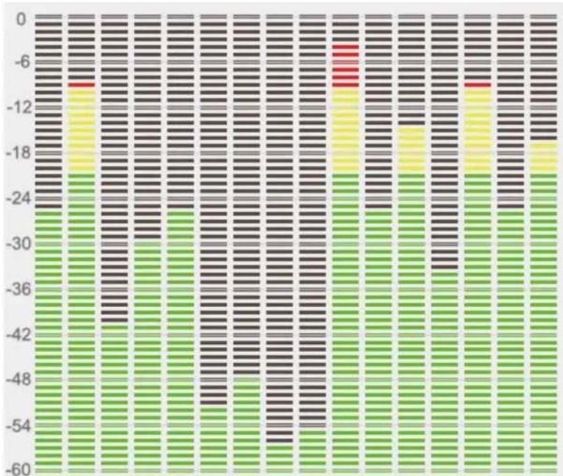
Note: If the monitor is in SDI mode, you will see 16 SDI embedded audio channels; in HDMI mode, there will be 8 HDMI embedded audio channels.
Audio Vector
Enable the audio vector scope shown below to view the audio information.

natural_image
Abstract 3D diagram with intersecting white lines and a green particle cluster on black background (no text or symbols)Audio Vector CH (HDMI)
First enable the audio vector scope, then select an audio input channel pair to view the audio information.
Audio Vector CH (SDI)
First enable the audio vector scope, then select an audio input channel pair to view the audio information.
Audio Left Out
Assign an audio channel to the left audio output channel.
An SDI input supports up to 16 embedded audio channels and an HDMI input supports 8 embedded audio channels.
Audio Right Out
Assign an audio channel to the right audio output channel.
An SDI input supports up to 16 embedded audio channels and an HDMI input supports 8 embedded audio channels.
System
In the System sub menu, you will be able to do the following:
- Change the language of the OSD menu
- Enable cross conversion
- Turn on the color bar
- Set the OSD ON time
- Flip the image
- Select color calibration
- Switch the standby power mode
- Reset the entire device's settings
Language
The available languages are English, Traditional Chinese and Simplified Chinese.
Color Bar
Available options are listed as follows:
OFF: disables the color bar
75% or 100% color bar
Color Bar Mode
The TLM-170F offers three color bar modes listed as follows:
• REC. 601: SD video
• REC. 709: HD video
• BT. 2020: 4K or 8K video
OSD Timer
This sets the OSD menu's ON time; the OSD menu will be automatically turned off after the timer times out.
• 10s
• 20s
• 30s
OSD Transparency
This sets the OSD menu transparency. You can set the transparency level to either 25% or 50%. Disabling this option will yield an opaque OSD menu.
OSD H Position
This adjusts the horizontal screen position of the OSD menu.
OSD V Position
This adjusts the vertical screen position of the OSD menu.
Fan
This allows you to turn ON/OFF the monitor's built-in fan. If you set this option to Auto, the fan will be turned ON if the monitor is overheated.
Color Calibration
To use this feature, you will need to purchase Light Illusion's LightSpace Color Management System (CMS) which includes a calibration probe and the CMS software. The TLM-170F works with CAL, PRO and XPT versions only. Visit https://www.lightillusion.com/lightspace.html for more information.
See the CMS Color Calibration Process in the subsequent chapter.
Comparison EN
By enabling this option, you will be able to see the difference between the original image and the image with the selected color setting applied as illustrated in the diagram below.

natural_image
Scenic mountain landscape with snow-capped peaks and rocky slopes under a blue sky (no text or symbols visible)| Gamma | HDR |
| Original | Color Space |
| Original | Camera Log |
Reset
Select ON to reset the device entirely.
5. Color Management System – Calibration Process
This chapter will discuss the use of Light Illusion's CMS software for color correction.
Device Setup
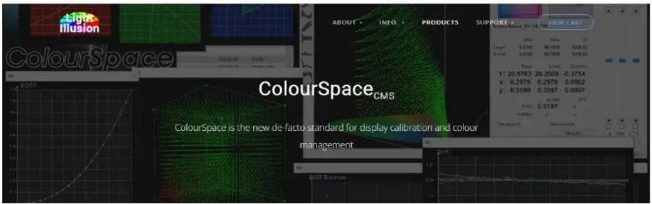
- Before starting the calibration process, you need to install and register the CMS software first. Copy and paste the link https://www.lightillusion.com/colourspace.html into your browser's address bar then hit enter to open the ColourSpace page shown below.
text_image
Light Illusion ColourSpace ColourSpace_CMS ColourSpace is the new de-facto standard for display calibration and colour management GOB BalanceBuilding on the unmatched capabilities of Light Illusion's previous calibration system, ColourSpace is a ground-up, and totally new product development that far exceeds the capabilities of any previous or present alternative calibration system.
Latest ColourSpace Release: 11 ^th December v1.0.0.1312
(Latest ZRO Release: 11th December v1.0.0.1312)
√ Unmatched Calibration Accuracy
√ Volumetric 3D graphs
√ Post & Broadcast
√ Medical
√ Pro AV
√ Home Cinema
√ Display Manufacturers
√ Free Updates
X. Yearly Maintenance Fee
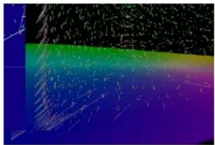
natural_image
Abstract color gradient background with no text or symbols? ColourSpace Options -
ADD TO CART
Professional Calibration
ColourSpace LTE - EG25
To discuss package deals, multiple license discounts, and alternate payment methods please use the Quote form
Unlike alternative calibration systems, ColourSpace licenses are valid for the life of the product (except for Rental licenses), with no expiry, no annual maintenance fee, and include free Software Updates for the purchased license options for the life of the product.

Note: There are different versions of the CMS software. Make sure you download the right version for your calibration device, for example, the LTE version is for Datacolor Spyder4/5, Eizo Internal, i1 Display Pro OEM, i1 Display 1/2/LT and i1 Pro 1/2. You will need higher versions for Minolta CA-310 and Klein series.
Click the link https://www.lightillusion.com/i1display_pro.html to purchase i1Display Pro OEM colourimeter.
Click the link https://www.lightillusion.com/murideo_six-g.html to purchase 4K & 8K signal generator. Please note that the signal generator is optional.
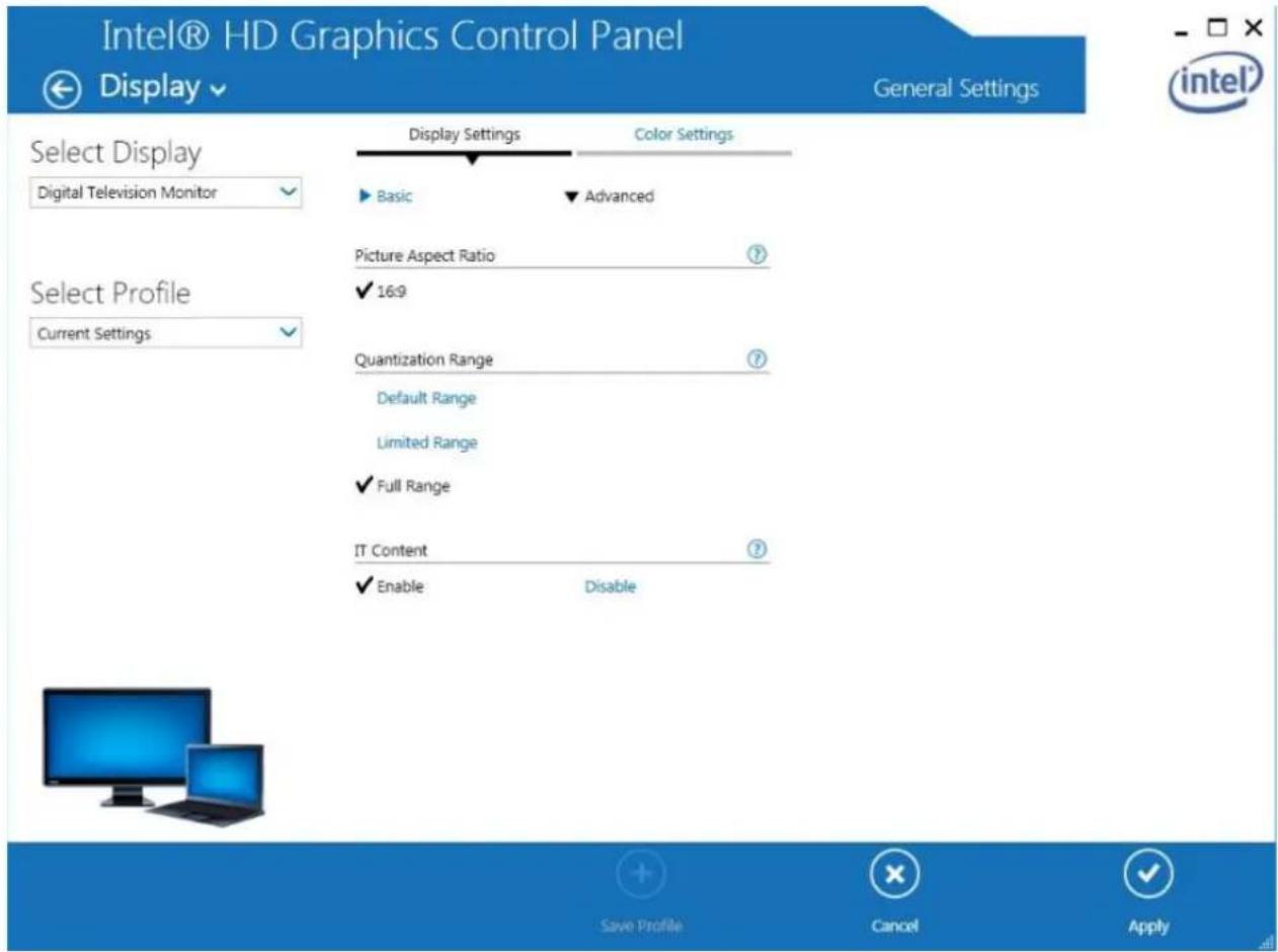
- Connect the calibration device to the PC or the laptop then the TLM-170F monitor via the HDMI interface. Enable Extended Desktop Mode on the PC or the laptop. Finally, open your graphics control panel to set the HDMI output to Full Range. The Intel HD Graphics Control Panel is shown in the diagram below for illustrative purposes.
text_image
Intel® HD Graphics Control Panel Display ▼ General Settings Select Display Digital Television Monitor Select Profile Current Settings Display Settings Color Settings Basic Advanced Picture Aspect Ratio 16:9 Quantization Range Default Range Limited Range Full Range IT Content Enable Disable Save Profile Cancel Apply- After you've successfully installed the CMS software, double click the icon below to open the software.

The CMS software interface is shown below.
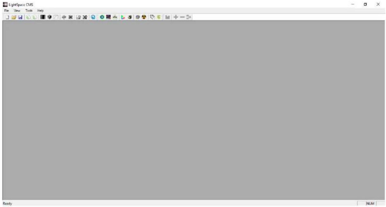
text_image
LightSpace CMS File View Tools Help Ready NUMPlease note that the monitor must be warmed up before calibration. Turn ON the monitor and the color calibration device and leave them running for about 30 minutes. You can start color calibrating your monitor after you've completed the device setup.
Software Setup
1. Select the connected "Probe"
Follow the path “Tools → Discoverable Probes” to access the color calibration devices supported by the CMS. Select the color calibration device that is connected to the PC or the laptop. The software setup guide will use i1Display Pro OEM for illustrative purposes.

text_image
LightSpace CMS - [Image4] File Edit Image View Tools Help Calibration Discoverable Probes Colour Space LUT Preview LUT Bum-In LUT Batch Conversion ASC CDL Batch Conversion Virtual Probe bacICColor DISCUS Cinebrate Colorimetry Research CR-100 Colorimetry Research CR-250 / CR-300 Datacolor Spyder4 Datacolor Spyder5 Eizo Internal Hubble / Sencore OTC1000 il Display Pro OEM il Display 1 / 2 / LT il Pro 1 / 2 Jet 1211 / 1201 / 1501 Klein K10 / K10-A / K90 Minolta CS-200 Minolta CA-210 / 310 Minolta CA-410 PR-655 / 670 / 680 image here2. Establish communication with the "Probe"
Because the CMS software does not establish connection with the color calibration device automatically, you will need to manually establish communication between the Probe and the PC.
Select "Tools → Calibration → Calibration Interface or Display Characterization"

text_image
LightSpace CMS File View Tools Help Calibration Discoverable Probes Colour Space LUT Preview Image Batch Conversion LUT Batch Conversion ASC CDL Batch Conversion Calibration Interface Display Characterization Network ManagerThe CMS should detect the probe and a dialogue box with the message "Do you want to connect to i1 Display Pro" should pop up.
Note: If the probe model is CA-310, you should see the corresponding model number in the message.
Click "OK" if the detected color calibration device is correct.
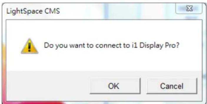
text_image
LightSpace CMS Do you want to connect to i1 Display Pro? OK Cancel3. Warm up the monitor before calibration.
Make sure the monitor and the color calibration device are turned ON and leave them running for about 30 minutes.
4. Enable the TLM-170F monitor's color calibration mode.
Open the TLM-170F's OSD menu, then select System → Color Calibration → ON.

text_image
SYSTEM Language English HDMI/SDI Convert Off Color Bar Off OSD Timer 30s Image Flip Off Fan Low Color Calibration On Comparison En Off ▼▲ HDMI5. Luminance calibration (adjust the backlight).
On the CMS User Interface, click Tools → Calibration → Calibration Interface to open the Calibration Interface window then click the Options button to open the window below.
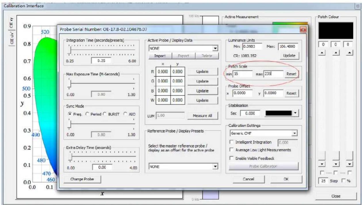
text_image
Calibration Interface Probe Serial Number: OE-17.8-02.104676.07 CIE Y 520 0.25 0.25 6.00 Max Exposure Time (M-Seconds) 0.00 0.00 1.00 Sync Mode Freq Period BURST AIO 0.00 0.00 1.00 Extra Delay Time (seconds) 0.00 0.00 4.00 Change Probe Active Probe / Display Data NONE Import Export Delete x y R 0.0000 0.0000 Update G 0.0000 0.0000 Update B 0.0000 0.0000 Update W 0.0000 0.0000 Update LUM 1.00 Measure All Reference Probe / Display Presets Select the master reference probe / display as an offset for the active probe NONE Luminance Units Min: 0.0983 Max: 106.4880 CR: 1083.352 Update Patch Scale min 15 max 235 Reset Probe Offset x 0.0000 y 0.0000 Reset Stabilisation Sec 0.000 Calibration Settings Generic CMF Intelligent Integration 0.000 Average Low Light Measurements Enable Visible Feedback Probe Calibration Cancel OK 490 480 470 460 x CloseLocate Patch Scale pane (circled in red in the diagram above), then enter 16 in min and 235 in max.
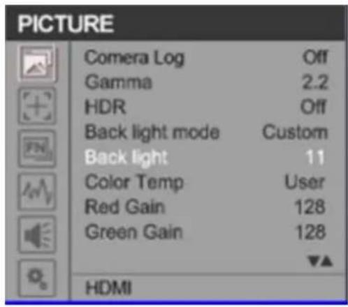
text_image
PICTURE Comera Log Off Gamma 2.2 HDR Off Back light mode Custom Back light 11 Color Temp User Red Gain 128 Green Gain 128 HDMIOpen the TLM-170F's OSD menu to adjust the monitor's backlight value and click the Update button in the Luminance Units pane located at the top right of the window above.
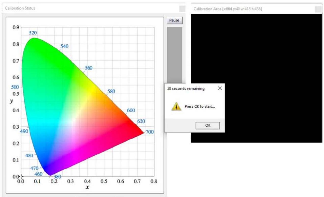
As soon as the Update button is clicked, the Calibration Status window will appear along with the Calibration Area and a dialogue box. Drag the Calibration Area to the TLM-170F. Lastly, point the probe at the calibration area as close as possible then click the OK button in the dialogue box to start calibration.
heatmap
| x | y | | ---- | ---- | | 0.1 | 0.85 | | 0.2 | 0.75 | | 0.3 | 0.65 | | 0.4 | 0.55 | | 0.5 | 0.45 | | 0.6 | 0.35 | | 0.7 | 0.25 | | 0.8 | 0.15 |Repeat the process until the MAX value in the Luminance Units pane is in the range of 80 – 120. Note that the closer the MAX value to 100, the better the TLM-170F is calibrated.
6. Color calibration
On the Display Characterization window (Tools → Calibration → Display Characterization), slide the Select Cube Side slider to 21 so that the Total Frames measured are 9261. Set Patch Sequence to Sequential and Select Time per Frame to Closed Loop Mode.

text_image
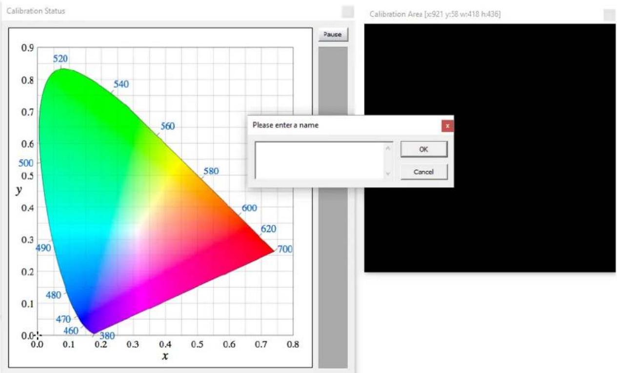
Display Characterization Cube | DPX Frames | CSV File | Select Cube Side 3 21 3D Cube Hybrid 1D + 3D Patch Sequence Anisometric Sequential 0 Drift Comp. Select Time per Frame DIP Mode Closed Loop Mode 16 Total Frames: 9251 Export Colour List Total Time: Variable Export Patches Close application when done Active LUT -- NO LUT -- Measure Options Manage Colour Space Network Manager Toggle Status Window CloseClick the Measure button, the Calibration Status window will appear along with the Calibration Area and a dialogue box. Drag the Calibration Area onto the TLM-170F. Lastly, enter a name for this particular calibration in the dialogue box, point the probe at the calibration area as close as possible then click the OK button to start calibration. Please note that it takes approximately one hour to perform 9261 point measurements.
contour
| x | y | | ---- | ---- | | 0.0 | 0.0 | | 0.1 | 0.1 | | 0.2 | 0.2 | | 0.3 | 0.3 | | 0.4 | 0.4 | | 0.5 | 0.5 | | 0.6 | 0.6 | | 0.7 | 0.7 | | 0.8 | 0.8 |7. Create a 3D Cube Color Calibration File

text_image
Convert Colour Space Source Colour Space: Rec709 RED GREEN BLUE WHITE X 0.6400 0.3000 0.1500 0.3127 Y 0.3300 0.6000 0.0600 0.3290 GAMMA 2.4000 Destination Colour Space: 20180609 Created on: 2018年6月9日 2 Number of Patches: 729 Enable Drift Compensation Limit Luminance Enable Maximum 105.7 Enable Minimum 0.0987 Name ColourSpace Image Out of Gamut Warning Map Space Create New Use Existing Manage CancelClick Tools → Colour Space → Convert Colour Space to open the Convert Colour Space window. In the Source pane, select Rec709 for the color space and in the Destination pane, select the color space generated in the previous step.
In the Name textbox, enter the name of the 3D cube color calibration file. The rest of the settings should be configured as shown in the diagram on the left. Click Create New button to generate the color conversion data.
Now click "File → Export" then select the "[3D] DaVinciResolve33 (*.cube)" format. Lastly click the Export button to export the 3D Cube file to a USB thumb drive.

text_image
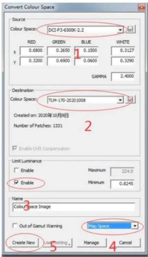
Select the formats Assimilate DaVinci [1D] DaVinci2K_ilutx_14bits (*.data) [1D] DaVinci2K_ilutx_16bits (*.data) [1D] DaVinci2K_olutx_12bits (*.data) [1D] DavinciResolve_4096 (*.cube) [3D] DaVinci17 (*.davlut) [3D] DaVinci33 (*.dat) [3D] DaVinci33 (*.davlut) [3D] DaVinciResolve21 (*.cube) ✓ [3D] DaVinciResolve33 (*.cube) [3D] DaVinciResolve65 (*.cube) [3D] DaVinciResolve66 (*.cube) 1 eeColor FSI LUT Light Illusion Video_Card_Gamma_Table_16bits (*.txt) Export Cancel Select All Select None Select a prefix or leave it empty if you want to use the default oneSettings and file exports of the DCI-P3 and BT2020 color spaces are depicted in the diagrams below.
DCI-P3
text_image
Convert Colour Space Source Colour Space: DCI-P3-6500K-2.2 RED GREEN BLUE WHITE X 0.6800 0.2650 0.1500 0.3127 Y 0.3200 0.6900 0.0600 0.3290 GAMMA 2.4000 Destination Colour Space: TUM-170-20201008 Created on: 2020年10月8日 Number of Patches: 1331 Enable Drift Compensation Limit Luminance Enable Maximum 224.0 Enable Minimum 0.8245 Name Colour space image Out of Gamut Warning Map Space Create New User Existing Manage Cancel
text_image
Select the formats Clipster Codex17_12bits (*.txt) Colorfront DaVinci [1D] DaVindi2K_ilutx_14bits (*.data) [1D] DaVindi2K_ilutx_16bits (*.data) [1D] DaVindi2K_olutx_12bits (*.data) [1D] DavindiResolve_4096 (*.cube) [3D] DaVindi17 (*.davlut) [3D] DaVindi33 (*.dat) [3D] DaVindi33 (*.davlut) [3D] DaVindiResolve21 (*.cube) [3D] DaVindiResolve33 (*.cube) [3D] DaVindiResolve65 (*.cube) [3D] DaVindiResolve66 (*.cube) DeviceControl Dolby65_14bits (*.dd3) eeColor EfilmColorCube19 (*.txt) Evertz_10bits (*.lut) FCP-Color 16_16bits (*.mga) Export Cancel Select All Select None Select a prefix or leave it empty if you want to use the default oneBT-2020
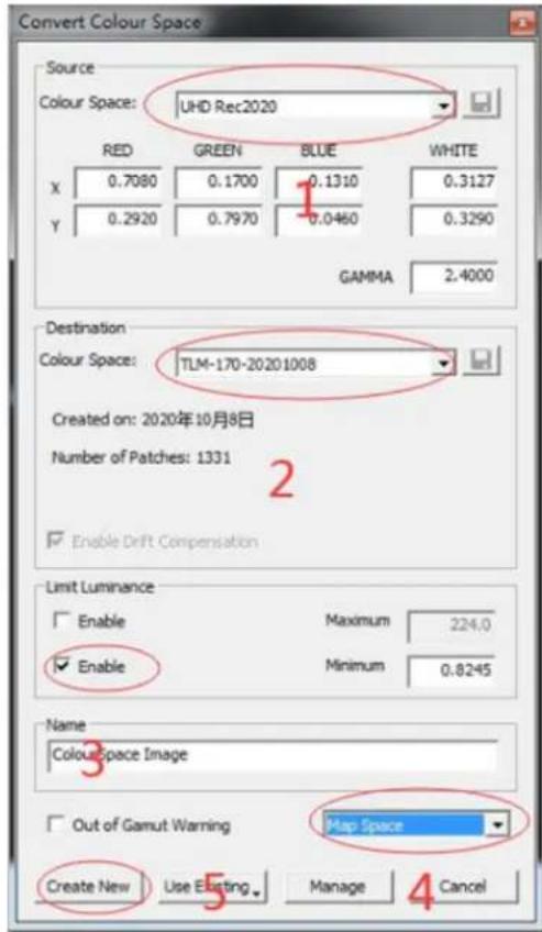
text_image
Convert Colour Space Source Colour Space: UHD Rec2020 RED GREEN BLUE WHITE X 0.7080 0.1700 0.1310 0.3127 Y 0.2920 0.7970 0.0460 0.3290 GAMMA 2.4000 Destination Colour Space: TLM-170-20201008 Created on: 2020年10月8日 Number of Patches: 1331 Enable Drift Compensation Limit Luminance Enable Maximum 224.0 Enable Minimum 0.8245 Name Colour Space Image Out of Gamut Warning Map Space Create New Use Existing Manage Cancel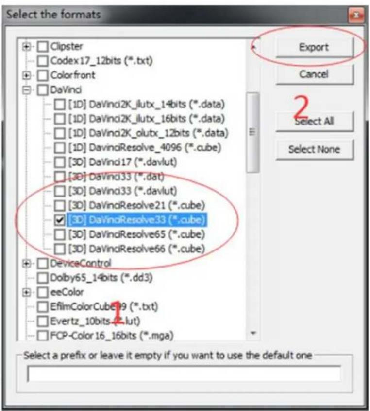
text_image
Select the formats Clipster Codex17_12bits (*.txt) Colorfront DaVinci [1D] DaVinci2K_lutx_14bits (*.data) [1D] DaVinci2K_lutx_16bits (*.data) [1D] DaVinci2K_olutx_12bits (*.data) [1D] DavinciResolve_4096 (*.cube) [3D] DaVinci17 (*.davlut) [3D] DaVinci33 (*.dat) [3D] DaVinci33 (*.davlut) [3D] DaVinciResolve21 (*.cube) [3D] DaVinciResolve33 (*.cube) [3D] DaVinciResolve65 (*.cube) [3D] DaVinciResolve66 (*.cube) DeviceControl Dolby65_14bits (*.dd3) eeColor EfilmColorCube19 (*.txt) Evertz_10bits (*.lut) FCP-Color 16_16bits (*.mga) Export Cancel Select All Select None Select a prefix or leave it empty if you want to use the default one8. Import the 3D Cube file to the monitor
Rename the three exported 3D cube files (REC709, DCI-P3 and BT2020) to "User1.cube", "User2.cube" and "User3.cube" respectively and save them on a USB thumb drive. Insert the USB thumb into the SERVICE port of the TLM-170F and you will be prompted whether to write the 3D CUBE file to the monitor. Select "Yes" to write the 3D Cube file to the monitor. The color calibration process is complete after the 3D CUBE file has been written to the monitor successfully.
Lastly, open the TLM-170F's OSD menu, select "PICTURE" → "User Log" then select the 3D CUBE file imported previously.

text_image
PICTURE Color Space Rec709 Camera Log User Log Def. Log SLog2ToLC-709 User Log User1 Gamma 2.4 HDR Off Back Light 100 Color Temp. 6500K HDMI16. Firmware Update
Datavideo usually releases new firmware containing new features or reported bug fixes from time to time. Customers can either download the TLM-170F firmware as they wish or contact their local dealer or reseller for assistance.
This section outlines the firmware upgrade process which should take approximately 20 minutes to complete.
The existing TLM-170F settings should persist through the firmware upgrade process, which should not be interrupted once started as this could result in a non-responsive unit.
Successful firmware upgrade on TLM-170F requires:
Latest TLM-170F firmware version
USB 2.0 Portable Drive (Max. 16GB)
USB A Cable
To update the TLM-170F firmware
MCU
- Unzip / extract the firmware file.
- Rename the bin file to "mcu.bin".
- Format the USB 2.0 pen drive to FAT32.
- Copy mcu.bin to the USB 2.0 pen drive.
- Power off the TLM-170F (On/Off Switch at the back of the monitor)
- At the back of the monitor, plug the USB 2.0 pen drive into the USB 2.0 port labelled SERVICE.
- Power ON the TLM-170F while pushing down the EXIT key.
- Release the EXIT key when the F1 button LED starts flashing (the firmware is being updated). The TLM-170K should reboot automatically after the update is complete.
- To check the firmware versions, push down the EXIT key for 3 seconds then release; push down the MENU key for another 3 seconds then release; push down the EXIT key for another 3 seconds again to show the firmware versions on the OSD menu.
| FPGA Ver | V1.1 |
| Software Ver | V1.3 |
| Back Light | 100 |
FPGA
- Unzip / extract the firmware file.
- Delete the contents of the USB 2.0 pen drive so it is empty.
- Copy the fpga.bit to the USB 2.0 pen drive.
- Plug the USB 2.0 pen drive into the USB 2.0 port labelled SERVICE on the back of the monitor.
- "Load FPGA..." appears on the screen as soon as the TLM-170F detects the fpga.bit file.
- fpga.bit is automatically loaded on the TLM-170F.
- The TLM-170F reboots itself after fpga.bit is successfully loaded.
-
The firmware update is complete if the TLM-170F Monitor reboots successfully.
-
Dimensions

單位:毫米(mm) -
Specifications
| LCD Display | |
| Size | 17.3 inch |
| Resolution | 1920 × 1080 |
| Pixel Pitch | 0.0995 x 0.0995 |
| Brightness | 300 cd/m2 |
| Contrast Ratio | 700 : 1 |
| View Angle (Typ.) | 178° (H) / 178° (V) |
| Interface | |
| Video Inputs | 1 x 12G SDI, 1 x HDMI (2.0) |
| Video Loop Through OUT | 1 x 12G SDI, 1 x HDMI (2.0) |
| Audio Inputs | Embedded Audio (48KHz sampling) |
| Audio Outputs | Analog stereo (Phone Jack)Speaker x 2 (3W) |
| Tally | 1 x Tally port |
| Firmware Update | USB 2.0 |
| Power In (12V) | 1 x XLR1 x Phoenix terminal (Pitch 5.08mm) |
| Standard | |
| SDI Signal Format | 4096x2160p (23.98/24/25/29.97/30/50/59.94/60)3840x2160p (23.98/24/25/29.97/30/50/59.94/60)4096x2160Psf (23.98/24/25/29.97/30)3840x2160Psf (23.98/24/25/29.97/30)1920x1080p (23.98/24/25/29.97/30/50/59.94/60)1920x1080i (50/59.94/60)1920x1080Psf (23.98/24/25/29.97/30)1280×720p (23.98/24/25/29.97/30/50/59.94/60)525i, 625i |
| HDMI Signal Format | 4096x2160p (23.98/24/25/29.97/30/50/59.94/60)3840x2160p (23.98/24/25/29.97/30/50/59.94/60)1920x1080p (23.98/24/25/29.97/30/50/59.94/60)1920x1080i (50/59.94/60)1280×720p (23.98/24/25/29.97/30/50/59.94/60)720 x480i (NTSC), 720 x576i (PAL)640 x800, 800 x600, 1024 x768, 1280 x800 |
| General | |
| Power | 12V/34.6W (12V/3A) |
| Operating Temperature | 0°C to 40°C (32°F to 104°F) |
| Storage Temperature | -20°C to 60°C (-4°F to 140°F) |
| Humidity | 10% to 80% (non-condensing) |
| Dimension (mm) | 403(L) × 305(W) × 36.6(D) |
| Weight | 4.1 Kg |
Service & Support
It is our goal to make owning and using Datavideo products a satisfying experience. Our support staff is available to assist you to set up and operate your system. Contact your local office for specific support requests. Plus, please visit www.datavideo.com to access our FAQ section.
Please visit our website for latest manual update.
www.datavideo.com/product/TLM-170F
www.datavideo.com/product/TLM-170FM
www.datavideo.com/product/TLM-170KR
datavideo
www.datavideo.com

@DatavideoUSA
@DatavideoEMEA
@DatavideoTaiwan
@DatavideoAsia
@DatavideoIndia2016
@Datavideojapan
@DatavideoLatam
@DatavideoBrasil

@Datavideo
@Datavideo EMEA
@Datavideo Taiwan

@DatavideoUSA
@DVTWDVCN

@DatavideoUSA
@DatavideoEurope