
RKQMCAB12V2 - Patch panel StarTech.com - Free user manual and instructions
Find the device manual for free RKQMCAB12V2 StarTech.com in PDF.

| Product Type | Server Rack Cabinet (Enclosure) |
| Brand | StarTech.com |
| Model | RKQMCAB12V2 |
| Form Factor | 12U Open Frame Rack |
| Rack Height | 12U (21 inches / 53.3 cm) |
| Width | 19 inches (48.3 cm) standard |
| Depth | Adjustable: 2.76 to 30.51 inches (70 mm to 775 mm) |
| Maximum Static Load Capacity | 9920.08 lb (450 kg) |
| Maximum Rolling Load Capacity | 694.46 lb (315 kg) |
| Weight (Empty) | Approximately 120 lb (54 kg) |
| Material | Heavy-duty steel with black powder coat finish |
| Front Door | Lockable perforated steel door (removable) |
| Rear Door | Lockable perforated steel door (removable) |
| Side Panels | Removable with key locks |
| Mounting Rails | Adjustable depth with numbered U positions; M6 cage nuts and screws included |
| Ventilation | Perforated front and rear doors for airflow |
| Grounding | Earth ground connection point; grounding wire (not included) |
| Leveling | Four adjustable leveling feet |
| Included Accessories | 1U fixed shelf, 50x M6 screws, 50x cage nuts, 2x door keys, 2x side panel keys, 10 ft hook-and-loop tape, user manual |
| Installation Requirements | Phillips screwdriver, open-end wrenches (10, 13, 14 mm), sockets (10, 13, 14 mm), level |
| Warranty | 5 years |
| Intended Use | Indoor, rack-mounted equipment storage |
Frequently Asked Questions - RKQMCAB12V2 StarTech.com
User questions about RKQMCAB12V2 StarTech.com
0 question about this device. Answer the ones you know or ask your own.
Ask a new question about this device
Download the instructions for your Patch panel in PDF format for free! Find your manual RKQMCAB12V2 - StarTech.com and take your electronic device back in hand. On this page are published all the documents necessary for the use of your device. RKQMCAB12V2 by StarTech.com.
USER MANUAL RKQMCAB12V2 StarTech.com
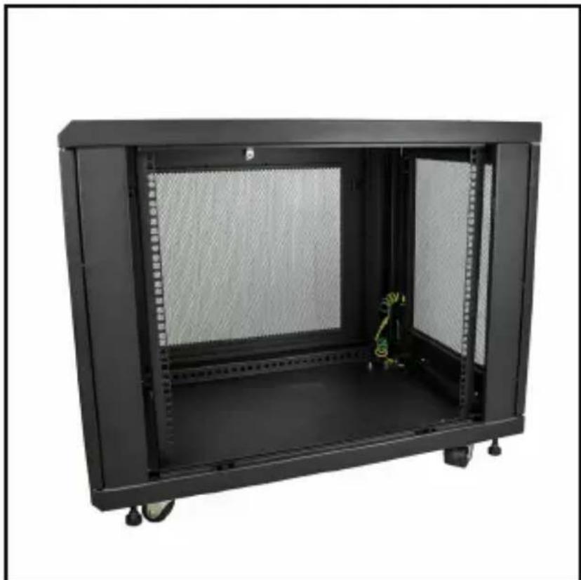
natural_image
Exterior view of a black industrial machine with mesh vent and door panel (no visible text or symbols)Actual product may vary from photos
User Manual
SKU#: RK1233BKM
For the latest information and specifications visit
www.startech.com/RK1233BKM
Use of Trademarks, Registered Trademarks, and other Protected Names and Symbols
This manual may make reference to trademarks, registered trademarks, and other protected names and/or symbols of third-party companies not related in any way to StarTech.com. Where they occur these references are for illustrative purposes only and do not represent an endorsement of a product or service by StarTech.com, or an endorsement of the product(s) to which this manual applies by the third-party company in question. Regardless of any direct acknowledgement elsewhere in the body of this document, StarTech.com hereby acknowledges that all trademarks, registered trademarks, service marks, and other protected names and/or symbols contained in this manual and related documents are the property of their respective holders.
To view manuals, videos, drivers, downloads, technical drawings, and more visit www.startech.com/support
Safety Statements
Safety Measures
- Wiring terminations should not be made with the product and/or electric lines under power.
- Product installation and/or mounting should be completed by a certified professional as per the local safety and building code guidelines.
- Cables (including power and charging cables) should be placed and routed to avoid creating electric, tripping or safety hazards.
Mesures de sécurité
To view manuals, videos, drivers, downloads, technical drawings, and more visit www.startech.com/support
• Make sure that you assemble this product according to the instructions.
- Do not exceed the weight capacity of this product. Overloading this product might result in injury or property damage. This product can support the following weight: Stationary = 9920.08 lb. (450 kg) Rolling = 694.46 lb. (315 kg).
- This product is intended for indoor use only and should not be used outdoors.
- This enclosure is extremely heavy. Never attempt to move or lift this enclosure without assistance.
- Tipping hazard! Extending multiple components from this enclosure increases the chance that the enclosure will tip over. To avoid this risk, do not extend more than one component from the enclosure.
- Do not place any items on this enclosure and do not stack the enclosure on top of another enclosure.
- Keep liquid away from this enclosure.
• Make sure that you install the enclosure in an area that can handle the combined weight of the enclosure and the equipment that you intend to place inside of the enclosure.
- This product requires an earth ground connection. Do not use this product without an earth ground connection.
Varningar
To view manuals, videos, drivers, downloads, technical drawings, and more visit www.startech.com/support
To view manuals, videos, drivers, downloads, technical drawings, and more visit www.startech.com/support
To view manuals, videos, drivers, downloads, technical drawings, and more visit www.startech.com/support
To view manuals, videos, drivers, downloads, technical drawings, and more visit www.startech.com/support
To view manuals, videos, drivers, downloads, technical drawings, and more visit www.startech.com/support
Table of Contents
Safety Statements....2
Warning Statements....3
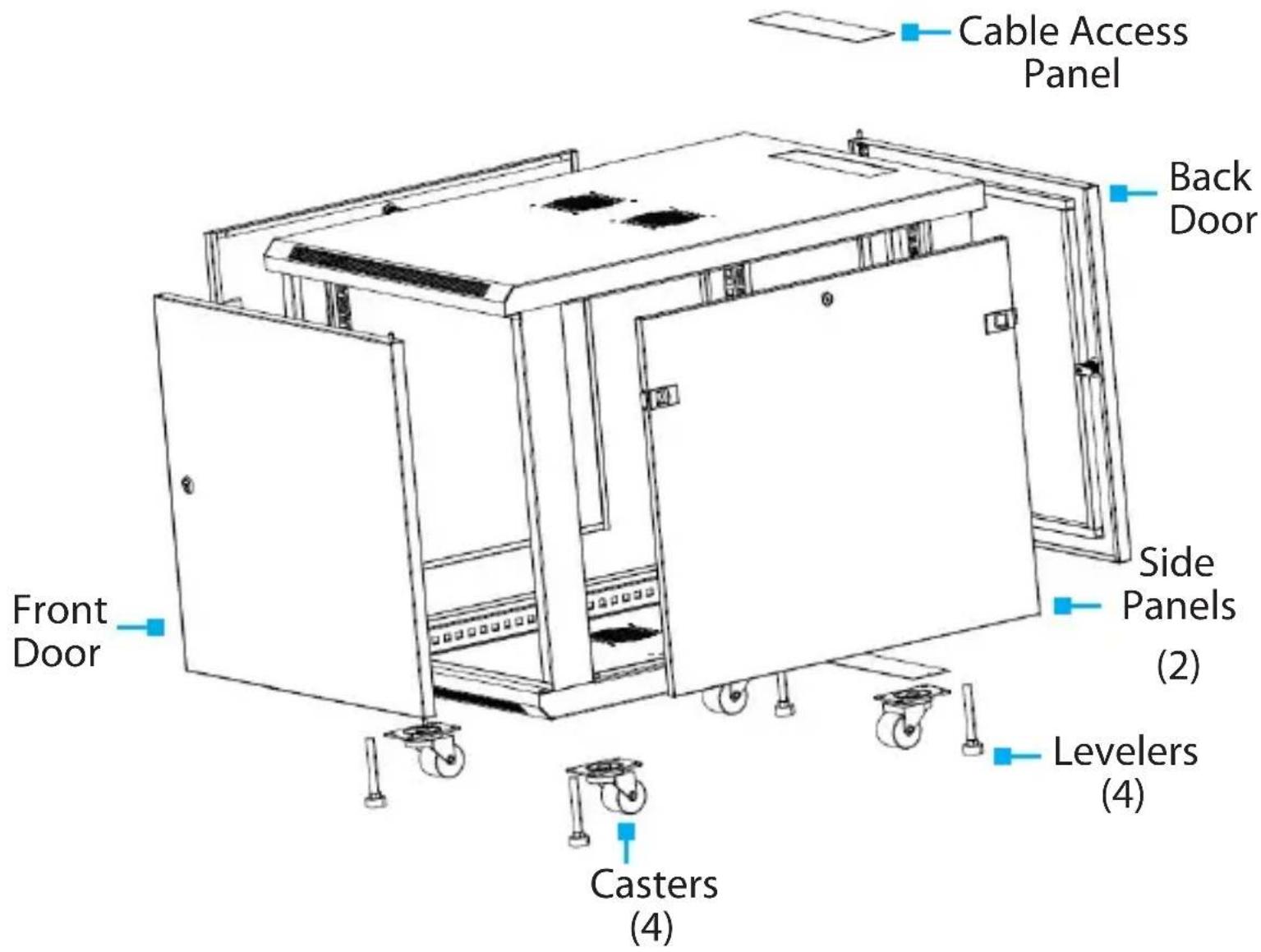
Product Diagram (RK1233BKM)....9
Product Information....10
Package Contents 10
Requirements 10
Unpacking the Rack....11
Installation....13
Leveling the Rack....13
Installing the Cage Nuts 14
Removing the Front and/or Rear Door....15
Removing the Side Panels 15
Installing the Side Panels .... 18
Grounding the Rack 18
Adjusting the Vertical Mounting Rails or Cable Management Rails....19
To view manuals, videos, drivers, downloads, technical drawings, and more visit www.startech.com/support
Product Diagram (RK1233BKM)
To view manuals, videos, drivers, downloads, technical drawings, and more visit www.startech.com/support
Product Information
Package Contents
• Enclosed Rack Cabinet x 1
• 1U Fixed Shelf x 1
• M6 Mounting Screws x 50
- Cage Nuts x 50
- Door Keys x 2
- Side Panel Keys x 2
• 10 ft (3 m) Hook-and-Loop Tape x 1
- User Manual x 1
Requirements
For the latest requirements, please visit www.startech.com/RK1833BKM
Installation:
The following Items required for installation are sold separately.
- Open-ended Wrenches x 3
- 10 mm
- 13 mm
- 14 mm
- Wrench x 1
- Sockets x 3
- 10 mm
- 13 mm
- 14 mm
To view manuals, videos, drivers, downloads, technical drawings, and more visit www.startech.com/support
- Level x 1
• Grounding Wire x 1
• Phillips Head Screwdriver x 1
Unpacking the Rack
Warnings: The Rack is heavy and you should exercise caution when you remove it from the Pallet.
At least three people are required to unpack the Rack. Do not attempt to unpack the Rack by yourself.
- Carefully move the shipping Pallet to a level surface.
- Remove the Tie Straps from the Shipping Carton.
- Remove the Shipping Carton being careful not to tip the Rack.
- The 1U Cabinet Shelf box will be shipped in the Rack's interior.
- Remove the Tie Straps from 1U Cabinet Shelf box and carefully lift the 1U Cabinet Shelf box out of the Rack through either the front or rear door.
To view manuals, videos, drivers, downloads, technical drawings, and more visit www.startech.com/support
- Using a 13 mm Socket and Wrench, remove the Bolts from the Pallet Brackets.

natural_image
Hand inserting a small mechanical component into a wall-mounted device (no visible text or symbols)Removing the Bolts
Note: Make sure that at least one person is holding the Rack in place while removing the Pallet Brackets.
- Carefully remove the Rack off of the Pallet and place it on a firm surface.
To view manuals, videos, drivers, downloads, technical drawings, and more visit www.startech.com/support
Installation
Leveling the Rack
The Rack will need to be properly level prior to the installation of any Rack Equipment to ensure stability. The surface the Rack is located must also be a flat level surface to support the weight of the Rack and Rack Equipment installed.
- Determine the location of the Rack. Once this location is determined, use the level to ensure that the surface is a flat level surface.
- Using an 14 mm Open-Ended Wrench, lower the leveler (4 located next to the Casters) by turning it clockwise until the base of the Leveler is tightly pressed against the surface, supporting the weight of the Rack.
- Place the Level on the top of the Rack to ensure that the Levelers are adjusted correctly. If the Rack is not level make the required adjustments to the Levelers until the Rack is level.
Securing the Rack to the Floor
You can use the Pallet Brackets and Bolts used to secure the Rack to the shipping Pallet to securely fasten the Rack to the floor.
- Align the two Pallet Brackets with the Bracket Holes on the bottom of the Rack's Door Frame. The Pallet Brackets can be mounted on the exterior or interior of the Rack.
- Using a 13 mm Socket and Wrench, insert two of the Bolts through the Pallet Bracket and into the Rack.
To view manuals, videos, drivers, downloads, technical drawings, and more visit www.startech.com/support
- Insert the other two Bolts through the Pallet Bracket and into the surface you are securing the Rack to.
Note: Pilot holes may need to be drilled in the surface you are securing the Rack to prior to installing the Pallet Bracket.
Installing the Cage Nuts
Note: When installing equipment in the Rack. Start at the bottom of the Rack with the heaviest equipment and work your way to the top.
- Determine the U-space of your equipment and where in the Rack you want to install the Devices.
- Apply pressure to both sides of the Cage Nut and insert the Cage Nut Clamps into the Cage Nut Hole and release the Cage Nut.
- or -
Use the included Cage Nut Wrench to install the Cage Nuts into the Rack.
-
Use the M6 Screws to secure the Devices in place.
-
If your Device has mounting brackets with hooks, just hook the bracket in the desired location.
Removing the Front and/or Rear Door
Note: At least two people are required when removing or reinstalling a Rack Door.
- With the door open at a 90 degree angle to the Rack Frame, lift the Door from out of its hinges and pull outward to remove it from the Rack's Door Frame.
Note: To reinstall the door reverse the steps above.
Removing the Side Panels
Notes: At least two people are required when removing or reinstalling the Side Panel from the Rack.
You may have to unlock the Side Panel prior to removal.
- While supporting the top portion of the Side Panel, pull both of the Locking Latches on the side panel toward the center of the Rack, to release the side panel from the Rack Frame.

natural_image
Front view of a black server rack unit with mesh vent and two red square buttons on the side (no visible text or symbols)Locking Latches
- Slowly tilt the top portion of the Side Panel away from the Rack Frame.
To view manuals, videos, drivers, downloads, technical drawings, and more visit www.startech.com/support
- While supporting the weight of the Side Panel, pull the bottom of the Side Panel away from the Rack Frame.
Note: The bottom of the Side Panel is hooked onto a lip on the Rack Frame.
natural_image
Black server rack cabinet with mesh insulation and visible internal components (no text or labels)Side Panel Removed
To view manuals, videos, drivers, downloads, technical drawings, and more visit www.startech.com/support
Installing the Side Panels
Note: At least two people are required when removing or reinstalling the Side Panel.
- While supporting the weight of the Side Panel align the bottom lip of the Side Panel with the lip on the Rack's Frame.
- Slide the lip of the Side Panel into the lip on the Rack's Frame.
- Push the top of the Side Panel into the Rack's Frame until you hear it click (lock) into place.
Grounding the Rack
- Insert an M6 Screw through the grounding point on the Grounding Wire (sold separately) and into the Ground Hole, located on the bottom of the Rack just inside of either the front or rear Door Frame.
- Run the Grounding Wire under the Rack's Frame to prevent obstructing the Rack Door from closing.
- Connect the Grounding Wire to an earth ground connection.
To view manuals, videos, drivers, downloads, technical drawings, and more visit www.startech.com/support
Adjusting the Vertical Mounting Rails or Cable Management Rails
The Mounting Rail Depth can be adjusted from 2.76" (70 mm) to 30.51" (775 mm).
Note: Follow the steps below to adjust the depth of the Mounting Rails.
-
Each Mounting Rail has two M6 Screws and two Cage Nuts securing the Mounting Rail to two Depth Adjustment Rails. One M6 Screw and Cage Nut is located at the top and one M6 Screw and Cage Nut is located at the bottom of the Mounting Rail.
-
Using a Phillips Head Screwdriver, remove the two M6 Screws from the Cage Nuts on the Mounting Rail.

natural_image
Close-up of a black server rack with a red square highlighting a component, no visible text or symbolsRemoving the M6 Screw
- Slide the Mounting Rail to access the Cage Nuts.
To view manuals, videos, drivers, downloads, technical drawings, and more visit www.startech.com/support
- Remove the Cage Nuts from the Depth Adjustment Rails by applying pressure to both sides of the Cage Nut.
- or -
Use a Cage Nut Wrench to remove the Cage Nuts from the Depth Adjustment Rails.
- Once you have determined the mounting depth reinstall the Cage Nuts into the Depth Adjustment Rails.
- Slide the Mounting Rail along the Depth Adjustment Rail aligning it with the Cage Nuts inserted in step 5.
Notes: The distance between each of the Mounting Rail Adjustment Holes is .827" (21 mm).
-
Insert the M6 Screws through the Mounting Rail and into the Cage Nuts.
-
Use a Phillips Head Screwdriver to tighten the M6 Screws.
Technical Support
StarTech.com's lifetime technical support is an integral part of our commitment to provide industry-leading solutions. If you ever need help with your product, visit www.startech.com/support and access our comprehensive selection of online tools, documentation, and downloads.
For the latest drivers/software, please visit www.startech.com/downloads
Warranty Information
This product is backed by a five-year warranty.
StarTech.com warrants its products against defects in materials and workmanship for the periods noted, following the initial date of purchase.
During this period, the products may be returned for repair, or replacement with equivalent products at our discretion. The warranty covers parts and labor costs only.
StarTech.com does not warrant its products from defects or damages arising from misuse, abuse, alteration, or normal wear and tear.
Limitation of Liability
In no event shall the liability of StarTech.com Ltd. and StarTech.com USA LLP (or their officers, directors, employees or agents) for any damages (whether direct or indirect, special, punitive, incidental, consequential, or otherwise), loss of profits, loss of business, or any pecuniary loss, arising out of or related to the use of the product exceed the actual price paid for the product.
Some states do not allow the exclusion or limitation of incidental or consequential damages. If such laws apply, the limitations or exclusions contained in this statement may not apply to you.
To view manuals, videos, drivers, downloads, technical drawings, and more visit www.startech.com/support
Hard-to-find made easy. At StarTech.com, that isn't a slogan. It's a promise.
StarTech.com is your one-stop source for every connectivity part you need.
From the latest technology to legacy products — and all the parts that bridge the old and new — we can help you find the parts that connect your solutions.
We make it easy to locate the parts, and we quickly deliver them wherever they need to go. Just talk to one of our tech advisors or visit our website. You'll be connected to the products you need in no time.
Visit www.startech.com for complete information on all StarTech.com products and to access exclusive resources and time-saving tools.
StarTech.com is an ISO 9001 Registered manufacturer of connectivity and technology parts. StarTech.com was founded in 1985 and has operations in the United States, Canada, the United Kingdom and Taiwan servicing a worldwide market.
Reviews
Share your experiences using StarTech.com products, including product applications and setup, what you love about the products, and areas for improvement.
StarTech.com Ltd.
45 Artisans Cres.
London, Ontario
N5V 5E9
Canada
FR: fr.startech.com
DE: de.startech.com
StarTech.com LLP
2500 Creekside Pkwy.
Lockbourne, Ohio
43137
U.S.A.
ES: es.startech.com
NL: nl.startech.com
StarTech.com Ltd.
Unit B, Pinnacle 15
Gowerton Rd., Brackmills
Northampton
NN4 7BW
United Kingdom
IT: it.startech.com
JP: jp.startech.com
- User Manual
- Use of Trademarks, Registered Trademarks, and other Protected Names and Symbols
- Safety Statements
- Safety Measures
- Mesures de sécurité
- Varningar
- Table of Contents
- Product Diagram (RK1233BKM)
- Product Information
- Package Contents
- Requirements
- Installation:
- Unpacking the Rack
- Installation
- Leveling the Rack
- Securing the Rack to the Floor
- Installing the Cage Nuts
- Removing the Front and/or Rear Door
- Removing the Side Panels
- Installing the Side Panels
- Grounding the Rack
- Adjusting the Vertical Mounting Rails or Cable Management Rails
- Technical Support
- Warranty Information
- Limitation of Liability
- Reviews
- StarTech.com Ltd.
- StarTech.com LLP
Brand : StarTech.com
Model : RKQMCAB12V2
Category : Patch panel