
AF-AN-B - Media Stand Atdec - Free user manual and instructions
Find the device manual for free AF-AN-B Atdec in PDF.


| Product Type | Notebook Tray |
| Brand | Atdec |
| Model | AF-AN-B |
| Weight Capacity | 0 - 8 kg (0 - 17.6 lbs) |
| Compatible Poles | Atdec AF series poles and arms |
| Mounting Type | Clamp-on pole mount |
| Material | Aluminum alloy and steel |
| Tilt Adjustment | Yes, lockable with 5mm Allen key |
| Pan Adjustment | Yes |
| Rotation | Optional rotation limiter for 180° rotation |
| Cable Management | Yes, with cable covers, clips, and stops |
| Handgrip | Yes, for height adjustment |
| Included Accessories | Notebook tray, hand grip, rotation limiter, cable covers, self-adhesive hook & loop fasteners |
| Installation Tools Required | 5mm Allen key (included in pole top cap) |
| Recommended Usage | With external keyboard and mouse |
| Cleaning | Wipe with a soft, dry cloth |
| Warranty | Contact Atdec for details |
| Safety Notes | Ensure proper installation; not responsible for incorrect installation |
| Repair | Contact manufacturer for service |
Frequently Asked Questions - AF-AN-B Atdec
User questions about AF-AN-B Atdec
0 question about this device. Answer the ones you know or ask your own.
Ask a new question about this device
Download the instructions for your Media Stand in PDF format for free! Find your manual AF-AN-B - Atdec and take your electronic device back in hand. On this page are published all the documents necessary for the use of your device. AF-AN-B by Atdec.
USER MANUAL AF-AN-B Atdec
natural_image
Technical line drawing of a mechanical component with threaded end and internal slots (no text or symbols)COMPONENT CHECKLIST
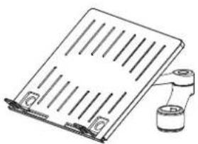
natural_image
Illustration of a flatboard with vertical slats and a cylindrical container attached (no text or symbols)A
Notebook tray assembly (x1)

B
Hand grip assembly (x1)

C
Rotation limiter (x1)

D
Primary arm cable cover (x1)

E
Secondary arm cable cover (x1)

F
Self adhesive hook & loop (x4 sets)
Desk

WEIGHT RANGE

0 - 8kg
(0 - 17.6lbs)
IMPORTANT INFORMATION
! Please ensure this product is installed as per these installation instructions.
! This product is designed to be used in conjunction with an external keyboard and mouse.
! This product is compatible with the range of AF poles and arms.
! The manufacturer accepts no responsibility for incorrect installation.
1. Remove existing arm and monitor from AF pole (Ensure monitor cables are unplugged)
1.1 Remove pole top cap and 5mmallen key from the Visidec pole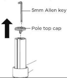 | 1.2 Quick release the monitor fromarm assembly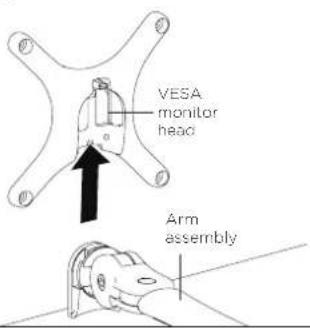 | 1.3 Remove the arm assembly from AF pole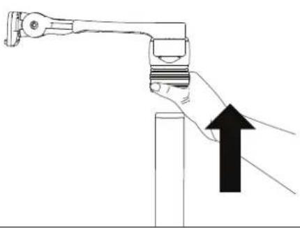 |
2. Attach notebook tray onto AF Pole
2.1 Slide the Handgrip onto the top of the Visidec Pole so the handgrip tab protrudes | 2.2 OPTIONAL ROTATION LIMITER Insert rotation limiter for 180° rotation around mounting pole | 2.3 Slip the notebook tray & arm assembly over the handgrip tab and then onto the pole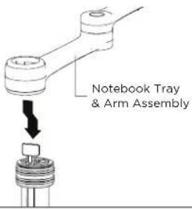 | 2.4 Slide the arm assembly and handgrip down the pole before locking the Handgrip  |
3. Re-install the existing arm and monitor
3.1 Slide the existing arm and monitor onto the visidec pole | 3.2 Lock the monitor arm handgrip in the desired position |
3.3 Insert pole top cap into pole.This is also where the allen key is stored | 3.4 Insert VESA monitor head into the receptacle in the arm assembly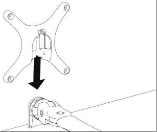 |
4. Install Notebook
4.1 Adjust the support tabs to suit the width of the notebook computer ensuring that cable ports are not obstructed

natural_image
Technical diagram showing two parallel metal supports with vertical rods and arrows indicating direction (no text or symbols)4.2 To increase stability, use the self adhesive Hook-and-Loop Fasteners supplied
- Peel off the backing paper to the fasteners
- Attach fasteners to both the Notebook Tray and computer
- Ensure that each set of fasteners are correctly aligned i.e. Hook to Loop

natural_image
Technical line drawing of a mechanical assembly with two components, no text or symbols present5. Cable Management
5.1 After plugging in your cables, install the Cable Covers
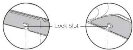

5.2 Push Cable Covers away from Elbow Joint to secure in place

5.3 Cable Clips and Cable Stops can be installed to further manage cables. Please See Over
Note: After connecting the Notebook Cables, route them through the Cable Management Clip on the back of the Notebook Tray.

6. Adjusting the display bracket
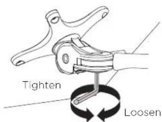
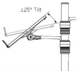
Adjust the tilt angle of the notebook tray as desired, locking it in position using the 5mm allen key

TILT (tray angle up/down)


PAN (tray angle left/right)
Brand : Atdec
Model : AF-AN-B
Category : Media Stand